3D scanner to cad file
Can A 3D Scanner Directly Output A CAD Model?
Answer | 5 Minute Read
The short answer is no. A 3D scanner cannot directly output a CAD model. This is because a 3D scanner outputs point clouds or mesh data, which acts as a single entity that is not editable.
You would need a Scan to CAD modeling stage to get scan data (not editable) to a CAD Model (building blocks and editable features).Let’s explain this concept using a camera as an example. A 3D scanner is just like a fancy camera, except instead of taking photos it captures scans of objects in 3D. If you take a photo of a car with a camera, you know that the photo has a car in it. However, your camera cannot interpret what exactly is in the picture. It only understands that the file is a picture. If you upload the photo into your computer to view it, likewise, the computer would only know that it is a picture, but not what the picture contains.
A 3D scanner is just like that. The computer program knows there is a scan but it has no idea what the scan is supposed to represent. You must interpret what the scan is. Then using CAD software on the computer, you sketch the object into a CAD model using the scan data as a tracing guide. Just like if you want to draw a realistic drawing of a car, it would be much easier to directly trace right on top of the photo than if you have to draw it from memory or just by looking at a photo.
Using scan data from a 3D scanner as a reference for design creates incredibly accurate CAD models. This process is known as Scan to CAD. You need this modeling step to bridge the gap before you can have a CAD model consisting of a solid CAD model with editable features, the design blueprint of the product for manufacturing.
This sounds rather complicated. Can you show me the Scan to CAD process?
It’s actually not too complicated once you understand the basics. Sometimes it’s easier to explain this with a simple demonstration. In this video, scan data was imported into SOLIDWORKS CAD modeling software. Mesh3Surface for SOLIDWORKS plugin that works natively inside the CAD modeling program was used to reverse engineer the part.
If you are already a SOLIDWORKS user, it’s a logical choice to use Mesh3Surface for SOLIDWORKS that works natively inside the CAD software to easily reverse engineering objects from 3D scanner data to CAD.
Point cloud or mesh output by the 3D scanner provides pertinent surface measurements about the object’s surface geometry which is useful in creating a CAD model of the part. The scan data functions as a template in building the new CAD model.
Once you go through this modeling stage, your output is a CAD model (STEP or IGES) which is now ready for manufacturing.
Then why use a 3D scanner to create a CAD model if I have to recreate it anyways?
Designing from a blank canvas can be an overwhelming project to take on. You might not get it right on the first try and may take you many versions to get you to the final CAD model you are happy with. Why not leverage knowledge from an existing object and learn from it which will make your work much easier and more accurate?
Reasons why to Scan to CAD:
- It’s more efficient than designing from scratch
- It gives you an accurate representation of the existing part to create the CAD model
- It gives you the ability to insert design intention and fix problems or damage
Creating CAD models through the process of reverse engineering from Scan to CAD gives you insights into designing better products but also do it in a faster amount of time than designing from scratch. This is especially true for objects with organic surfaces.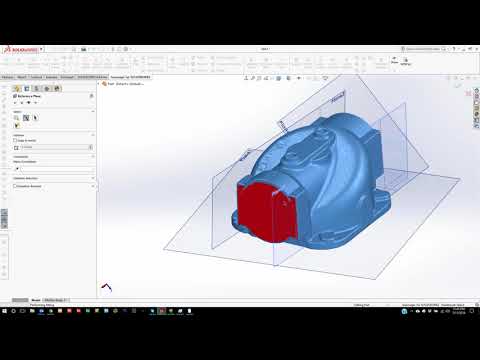 A 3D scanner makes reverse engineering faster and much simpler than if you have to do it without aids. Instead of trying to get complex curves and angles just right, reverse engineering gives the user the ability to snap onto the curve and create an identical profile. If the profile is incorrect or the physical part has any damage, then the designer has the power to see where the old geometry is and has the ability to correct it.
The Best 3D Scanners and Scan-to-CAD Softwares
Computer-aided design (CAD) is defined as the use of computers to assist in the creation, modification, or optimization of a design. CAD software enables designers and engineers to model shapes and add features with the ultimate goal of producing parts. The CAD process, however, is a closed digital procedure, meaning that all of the functions happen digitally inside the computer. But how do we get into this process, knowing that, of course, we cannot insert a physical object into a computer?
New parts can be designed entirely and directly in CAD software or they can be hand-sculpted using clay or other materials.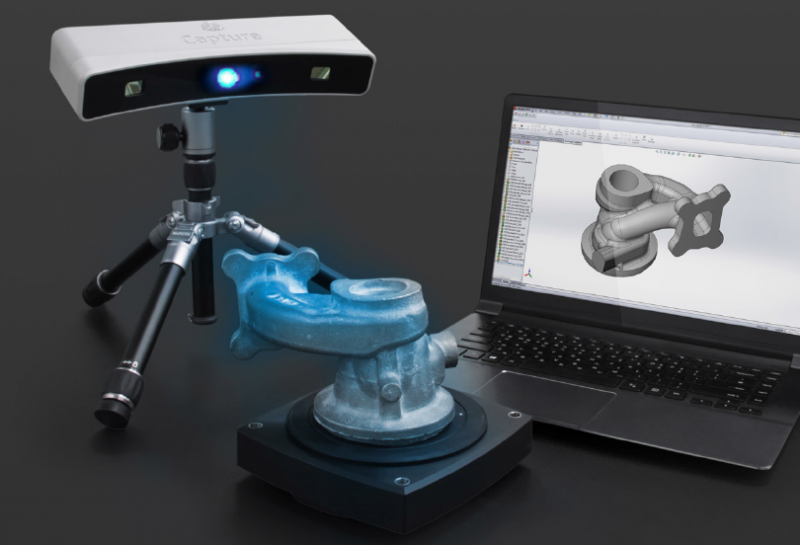 Obsolete parts and damaged components must not be forgotten, as they often need to be updated, replaced, or fitted into a new assembly or environment. Thus, a bridge between the physical and the digital world is necessary to transition from an existing object to a CAD model. The process of converting a physical object into a virtual 3D model is called reverse engineering, and the bridge between worlds can be crossed thanks to 3D scanning.
When designing new products or adapting existing parts, engineers and designers like to use 3D scanners as a starting point for digitizing clay models or measuring physical objects in order to reconstruct their 3D models and integrate them into their designs.
But the role of 3D scanners does not stop at the design stage. They can be used throughout the entire product development process. After manufacturing, 3D scanning participates in quality control by checking that the part is accurate and conformed to the CAD model. Next, as parts are used, 3D scanning can reveal if there are deformations, showing engineers and designers where reinforcements, improvements, or variations should be added in the next version.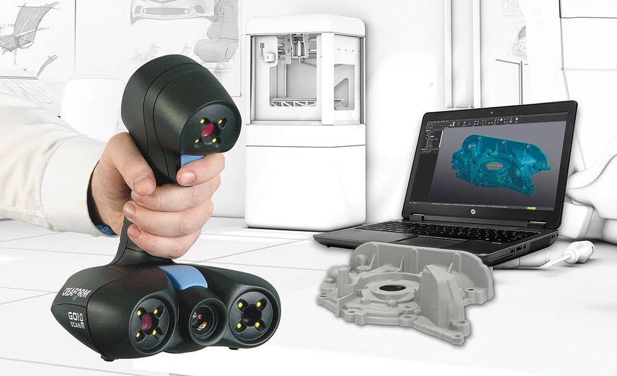
In this post, “3D Scanner for CAD” we want to guide you through the process of reverse engineering and demystify the process from a 3D scan to a CAD model. We also want to address the quality of 3D models generated with 3D scanners. Finally, we wish to help you choose the best 3D scanner and Scan-to-CAD software based on your needs and budget.
- 1 The Way to CAD
- 1.1 Can a 3D Scanner Directly Output a CAD model?
- 1.2 How Good are Generated 3D Models, and is Post-Treatment Required?
- 2 Selection of 3D Scanners and Scan-to-CAD Software
- 2.1 Do You Need a Stationary or Mobile 3D Scanner?
- 3 3D Scanners for CAD and Reverse Engineering
- 4 Ways from 3D Scan to Final CAD Model
- 5 Benefits of 3D Scanning for CAD Designers
Let’s say you have to replace a damaged component or update an obsolete part for which the original CAD model is nonexistent or inaccessible.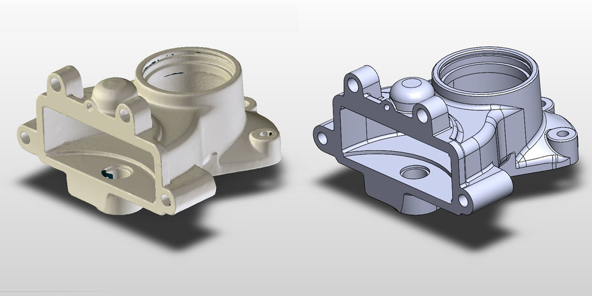 So, you have to create a new CAD model for manufacturing. You can either start your CAD design from a blank canvas, which is likely to be a long, overwhelming iterative process, or you can leverage the data you already have from the existing object and use that information as a foundation for your design, which will make your work more accurate and effective. This avenue involves 3D scanning.
Here are the typical steps to create a virtual 3D model from an existing physical object:
- Obtain the 3D scan mesh (STL) by 3D scanning the part.
- Extract dimensional information, such as geometries, dimensions, and cross-sections.
- Import models into CAD software and proceed with CAD modeling.
- Compare the resulting CAD model (STEP or IGES) with the initial 3D scan mesh.
- Analyze feedback and use the comparison to optimize the CAD reverse modeling.
- Export the final CAD model of the part for manufacturing.
Can a 3D Scanner Directly Output a CAD model?
In short, the 3D scanner produces a mesh, or point cloud, which provides all of the needed dimensional information about the part’s surface geometry.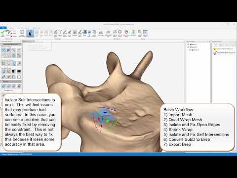 This mesh can then serve as a template to sketch the new CAD model. CAD models are usually created using non-uniform rational basis spline (NURBS), which consists of points connected by curves, while 3D scans are typically exported as meshes, which are made of millions of small triangles.
Thus, a 3D scanner does not directly output a CAD model. An intermediate Scan-to-CAD modeling stage is necessary to bridge the gap and convert non-editable triangles into editable NURBS surfaces, with which you will be able to create a solid CAD model with editable features.
How Good are Generated 3D Models, and is Post-Treatment Required?
Based on your needs, there are different methodologies available to build a CAD model from an existing object. You may want to (1) reproduce a CAD model with accurate dimensions and precise angles to develop and manufacture new parts, or (2) reproduce an exact copy of a part (usually made of organic shapes) in its current condition. The first possibility creates a design intent and outputs a parametric model.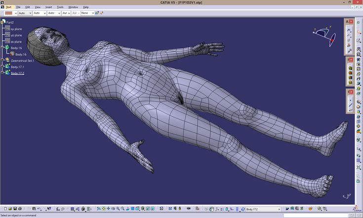 The second option provides an as-is reproduction and outputs a surface model. Hybrid models also exist, which combine both methods for different areas of the object.
To get a parametric model from a 3D scan mesh, you first need to understand how the object was conceived. To do so, you must extract information from the scan data by creating entities, such as planes, cylinders, or cross-sections, on the mesh. These operations take place directly in Scan-to-CAD bridge software, such as VXModel. The parametric model and its entities can then be transferred to your preferred CAD software.
Similarly, to get a freeform surface model based on an optimized 3D scan mesh, you need to recreate the exact shape of a scanned object. To do so, you must improve and optimize the mesh by filling holes, smoothing surfaces, and trimming boundaries. Then, on the optimized mesh, you can create accurate freeform surfaces (NURBS) with control points. Again, all of these operations happen directly in the Scan-to-CAD bridge software before importing the freeform surface model into CAD software.
The 3D scanner does not generate NURBS surfaces (STEP or IGES) directly, but the Scan-to-CAD bridge software can. Nevertheless, the 3D models must then be imported into CAD software to get a parametric model for design intent.
Selection of 3D Scanners and Scan-to-CAD SoftwarePrior to choosing a 3D scanner and Scan-to-CAD software, you must identify your needs.
- What is the size of the part you want to scan?
- Is its geometry simple or complex?
- Can you easily move the part to the scanning session?
- What accuracy and level of detail do you need?
- What is your budget?
Do You Need a Stationary or Mobile 3D Scanner?
Stationary scanning systems are an option for limited budgets, but—as their name indicates—they require the part to be brought to the system, and they are mostly suitable for parts that are limited in size. Mobile scanners, which include both articulated arms and handheld scanners, are usually more accurate and better suited for large parts, and—as their name suggests—they go to the part rather than the other way around.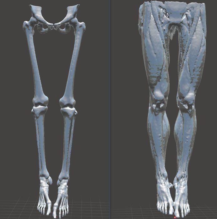
Creaform offers a variety of handheld 3D scanners, but three series stand out for product development and reverse engineering applications. Based on your budget and specific speed and accuracy requirements, a Creaform 3D scanner can certainly meet your needs.
The HandySCAN 3D | SILVER Series offers the best value for the money for technology innovators who wish to develop better products that are more suited to customer needs. This proven and trusted technology is accessible to low budgets and can shorten the development process.
The Go!SCAN SPARK offers the fastest and easiest 3D experience for product development, design, and reverse engineering. It enables the development of new products, with more complex shapes and designs, and gives a competitive edge by accelerating the time-to-market.
The HandySCAN 3D | BLACK Series is the most reliable and accurate ISO 17025-accredited portable 3D scanner available on the market.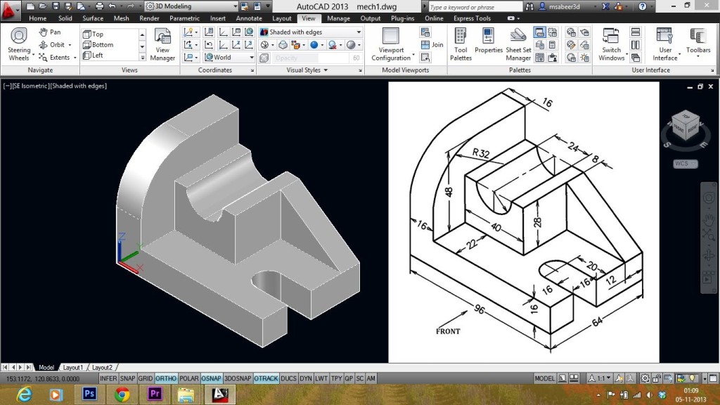 It can generate accurate 3D measurements and high-resolution results with the best scan quality.
As previously mentioned, 3D scanning and CAD modeling are like two different subway lines that require 3D Scan-to-CAD software to connect them efficiently.
One avenue is to opt for complete reverse engineering (RE) software, such as Geomagic Design X, which offers high-performance functionalities for alignment, information extraction, and feature modeling. Complete RE software basically replaces CAD software for reverse engineering activities. In fact, it is a ”high-end solution” for designers who do RE on a daily/weekly basis. Consequently, designers who usually feel comfortable with their preferred CAD software must learn to use new software with different features. It is also more expensive than the other options.
Another way is to start the design from a blank canvas directly in CAD software without resorting to reverse engineering. CAD software is known to be designers’ favorite place for feature modeling, but developing a sketch from nothing can be a long and tedious journey. In addition, CAD software has limited functionalities for mesh editing, alignment, and information extraction from the mesh.
A more appealing approach is to choose Scan-to-CAD bridge software, such as Creaform’s VXmodel, which includes all of the functionalities to align, clean, and optimize the mesh as well as to extract dimensional properties before transferring the entities and cross-section into CAD software, such as SOLIDWORKS, Autodesk Inventor, and Solid Edge, where designers can comfortably proceed with feature modeling. This option is more appealing because it is less expensive than complete RE software; it is also simpler to use and easier to learn.
Benefits of 3D Scanning for CAD DesignersThe benefits of using reverse engineering from Scan to CAD to create CAD models are important. It enables designers and engineers to create their 3D models from existing parts in less time, reduce the number of iterations leading to a part ready for manufacturing, and get a perfect fit of retrofit parts the first time.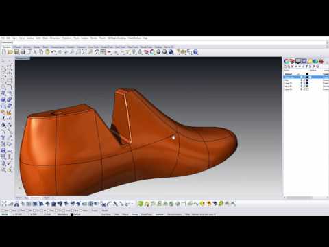 It can also shorten product development and time-to-market. But, more importantly, it provides an accurate foundation on which designers and engineers can build and improve their models—instead of starting from scratch—giving them more means to conceive complex geometries, modern shapes, and organic surfaces.
Scan-to-CAD bridge software is also ideal for CAD experts, as it is the shortest path back to your workflow and preferred CAD modeling software. Why learn completely new RE software when you’ve already mastered SOLIDWORKS, Autodesk Inventor, and Solid Edge?
In short, products designed through reverse engineering from Scan to CAD are not only of better quality, but also they are market-ready with fewer iterations and in less time. This is particularly valid for complex parts with intricate geometries. Creaform professional 3D scanners, such as the Go!SCAN SPARK, make reverse engineering more efficient, faster, and simpler. Scan-to-CAD bridge software, such as VXModel, leads you back to your preferred CAD software faster than any other solution, so you can get back to the joy of designing and innovating!
Data processing obtained after 3D scanning
Reverse engineering
Experts recommend
Author: Aleksey Chekhovich
Author: Aleksey Chekhovich
CAD software | Reverse engineering software | Software for processing 3D scan data in CAD
Computer-aided design (CAD) software is a key element in the product lifecycle management process to reduce time to market, improve product quality and reduce costs. Without it, product development would be much more difficult and time consuming. nine0003
3D scanning makes it possible to quickly and easily obtain accurate CAD files of models of physical objects. Portable 3D scanners are now a must-have, as they allow engineers to go the extra mile to get CAD files from competitors or even their own products. Now you can start from the scanned file and use different software to develop and test new products.
To move from 3D scanning to CAD design, designers can choose between three workflows: nine0003
- CAD software,
- software for complete reverse engineering (RE),
- Scan to CAD data processing software.
Each of these options has both pros and cons listed below. Which option to choose depends on the specific needs of the developer, the frequency of use and the allocated budget.
CAD software nine0029
This workflow is done entirely in the CAD software, where the . stl CAD file is imported and the mesh is cleaned and aligned. After the scan results are cleaned and the grid is applied, information about the parameters and functions is retrieved. Now you can start modeling features to get the final CAD model.
| FOR | VS |
| The operation history is stored in the CAD software. If a function changes (for example, openings increase or decrease), then all related functions will be updated without the need to redo anything. | Compared to other software, CAD software is limited in meshing, cleaning, decluttering, filling empty space, and flattening. Some CAD programs don't even allow developers to edit the mesh and only allow it to be used as a visual reference. nine0038 |
Reverse engineering software
This process begins by working in reverse engineering (RE) software, where the mesh is created, edited, and aligned.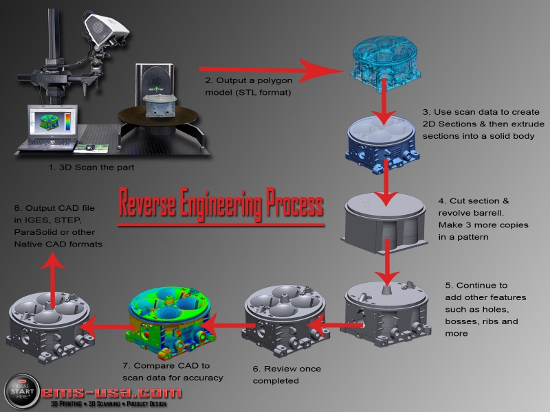 After the scan results are cleaned and aligned with the desired coordinate system, information about the parameters is extracted. Modeling of CAD functions is performed in the RE software before transferring the 3D model to the CAD software and obtaining the final CAD model. nine0003
| FOR | Vs |
| The RE software offers high performance editing and mesh alignment functionality. Operation history can be transferred from RE software to CAD software. | CAD and RE software may have compatibility issues and transfer of operation history may not be as smooth as expected. nine0078 This software package option is more expensive than other options. Developers, often very experienced and familiar with CAD software, must learn to use the new software with other features. |
CAD 3D Scan Data Processing Software
After the mesh has been generated, aligned, and optimized, parameter information is extracted using geometric objects, cross sections, and constrained closed curves (for free-form objects).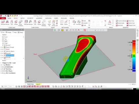 These objects can then be transferred to the CAD software and used as reference data on which to base the modeling of the functions that describe the rigid body. The final validation step, comparing the resulting CAD model to the mesh, completes this process and results in the final CAD model. nine0003
| FOR | Vs |
| This option is cheaper than the full RE software and is simple and easy to use. Scan to CAD software allows CAD developers to access CAD software faster. | Sometimes you need to move from one application to another when additional features are needed. nine0038 |
Material provided by Creaform
Article published on 01/29/2019, updated on 05/14/2021
3D Scanning and Geometry Inspection
Geometry inspection using 3D scanning is used at every stage of the production of a part.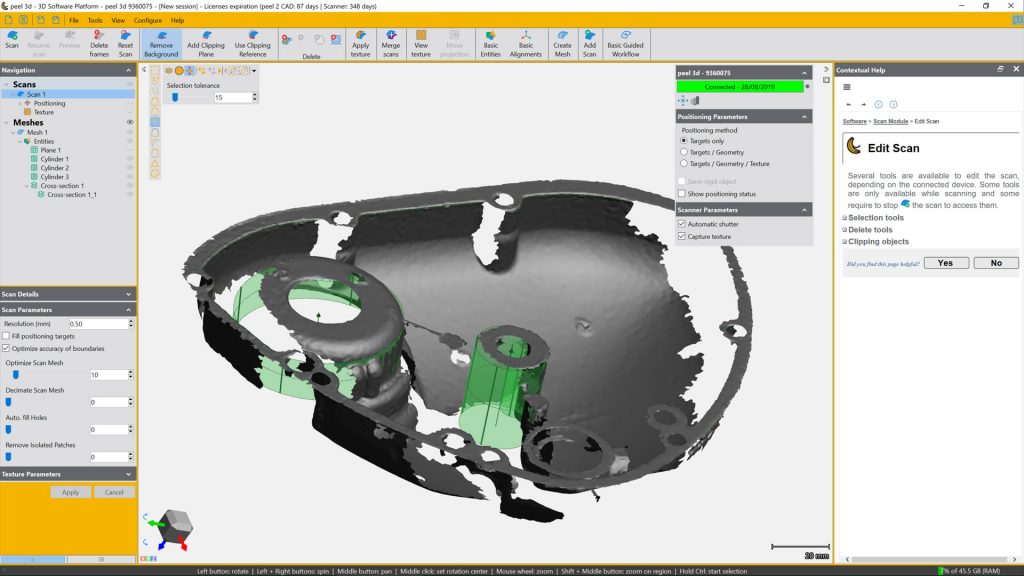
The capabilities of the equipment allow you to digitize the surface and compare the scanned data with the original CAD model. Based on the results of such a comparison, a report with a deviation map is generated. nine0003
The geometry of products is controlled on a non-contact scanner and a coordinate measuring machine.
3D scanner GOM Atos Comact Scan 5M
Geometry check with non-contact 3D scanner
| Specifications: | |
|---|---|
| Precision | |
| 0.020 mm | in volume 300x230x230 mm |
| 0.035 mm | in volume 600x450x450 mm |
3D surface scanning is performed using Blue Light technology - based on the use of structured blue light, two high-resolution digital cameras and special software. Thanks to this, it is possible to digitize parts from all sides and with an unlimited number of setups. Thus, you can scan parts of any complexity and size.
Geometry control
Control of part geometry deviations, determination of casting allowances during machining.
To control deviations in the geometry of the surfaces of a part, a 3D scan of the surface of the object is first performed.
The scanned data is then compared to the original CAD model from which the part was made.
Deviations over the entire surface are displayed as a color map, on which the deviations are visually indicated by color. nine0003
Deviation maps allow you to draw a conclusion about the deviation of the geometry of the part from the CAD model, and are convenient when choosing a strategy for further processing, since they allow you to "fit" the part into existing allowances.
The geometry mapping report is saved as a PDF file. Reverse engineering nine0078 This procedure produces an editable CAD model using scanned data.
3D scanning provides source data in the form of a Point Cloud.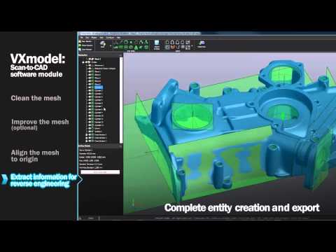 This data set contains points taken from the surface of the part, they are described by three coordinates.
The point cloud is almost never used for further work and is immediately converted to a polygonal mesh (Mesh).
Using a polygon mesh, the designer creates a solid CAD model. The resulting model can be edited or used as input for designing other parts. nine0003
You can save the CAD model as a native PRT file or in universal formats - STP, IGES and STL.
Stages of reverse engineering
Scan of the metal part
The result of the 3D scanner-Point Cloud
Polygonal surface (MESH)-Processed Data
Solid-state CAD-Model
Field deviations - the result of comparing scan data and CAD model
Drawing
DEA Global Performance Coordinate Measuring Machine
| Specifications: | |
|---|---|
| Working area | 900x1200x800 mm |
| Precision | 1.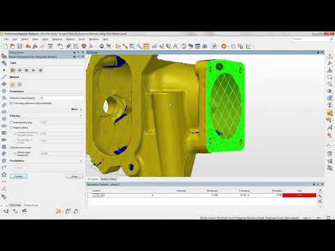 |