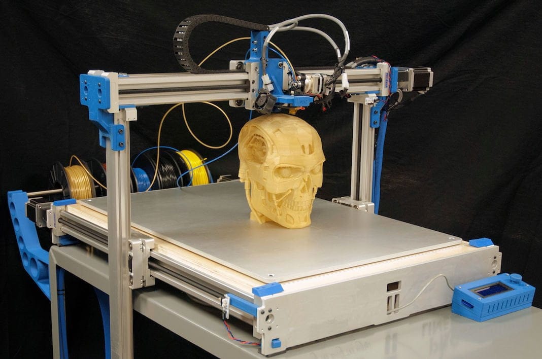
3D scanner components
3D Scanning - Parts & Objects
What Is 3D Laser Scanning?
3D laser scanning, the process of converting physical objects into precise digital models, enables you to quickly and accurately capture your object’s shape and geometries. Raw 3D scan data consists of millions of XYZ data points, called “point clouds,” which can be manipulated and delivered in a number of native file formats. This process supplies you with a complete digital representation of your part to be used for reverse engineering, quality inspection, or analysis at any point of a typical manufacturing cycle.
3D laser scanning technology can provide you with:
Give our 3D Scan team a call! 952-252-3479
- Fast, ultra-accurate results, reducing your time to market and cutting labor and material needs—saving you both time and money! When compared to traditional hand measuring methods, 3D scanning services are exponentially more efficient, quick, accurate, and detailed.
- Complete measurement data of the entire surface of your object, verifying that the as-built part matches your CAD model.
Discovering any defects or deviations from the design-intent model will allow you to readjust sooner and keep your project or production on track.
- True CAD models for FEA testing of actual geometry to correct problems before parts go into production. This application can allow you to conserve valuable resources and manpower.
- CAD models to validate tooling, even when no current models exist. Because 3D scanning is non-contact and non-destructive, you’ll be able to safely and effectively capture data for unique, delicate, complex, or tiny parts and prototypes.
- Profile data of the whole part so assemblies can be digitally put together, revealing inaccuracies and interferences.
- Customized digital models of your parts in whatever format you need them in, with whatever level of detail, color, and texture you require. You won’t need to struggle with an unfamiliar file format—our scanning services team can deliver your data in a variety of file formats. We can convert raw 3D scan data into a SOLIDWORKS CAD model, for example.
3D Laser Scanning Deliverables and Applications
With 30 years of successful 3D scanning projects under our belts, Laser Design can scan everything from tiny components to vehicles and even entire buildings. We provide customers with unparalleled technology and expertise, both on-site and in our lab. Our 3D scanning services team is eager to work with you to identify the right solution for your project—and then put it into action.
We can deliver in many native formats:
- AutoCAD
- SolidWorks
- Pro/E
- CATIA
- UG
- IDEAS
- Autodesk Inventor
- Rhino
- Revit
- CAE/CAM
- And others
Whether comparing a physical part to its CAD model, digitizing a prototype with the intent of developing a new CAD model, or generating missing parts documentation, the 3D scanning process yields high-accuracy point cloud data that can be modeled and used for just about anything under the sun. The following are just a few of the many possible uses for 3D scan data:
- Tool path creation
- Polygonal / STL meshes
- Composite blends
- NURBS curves
- NURBS surfaces
- Tooling verification
- And many more
How 3D Scanning Services Can Streamline Your Project
You don’t have to be a 3D scanning expert or purchase your own equipment to benefit from this versatile technology—that’s where we come in. Partnering with Laser Design’s 3D scanning services bureau will make executing a successful project that much simpler.
- Whether you have a one-off project or require ongoing 3D scanning services, our team will be available wherever and whenever you need us.
- With our experienced 3D scanning technicians on your side, there’s no learning curve to worry about. We’ll scan and process your data, providing the exact output you need for your purposes.
- If you need tight turnaround on a budget, you’ve come to the right place.
 Our 3D scanning services are cost-competitive and significantly faster and more accurate than traditional hand measuring.
Your Guide to Choosing the Best 3D Scanner for Small Objects
Small components present particular challenges for measurement. Certain aspects of small parts contributing to these challenges include the fine level of detail required, the scale of dimensions and crevices between features, and the difficulty in setting up and positioning small objects.
If you'd like to skip to a specific section, click the section below to jump straight to it:
- Examples of Small Objects for 3D Scanning
- Budget vs. Functionality for 3D Scanners
- 3D Scanner Resolution & Quality
- 3D Scanning Versatility
- Scanning Sensor Repeatability & Precision
- 3D Scanning Ergonomics and Automation
- Handheld 3D Scanning
- Stationary Supports for 3D Scanners
- Semi and Full-Automation 3D Scanning
- Measuring Volume Options for 3D Scanners
Non-contact 3D scanning helps overcome these challenges by collecting complete measurement data, also known as full-field measurement data. Due to the ability to capture intricate details, 3D scanning is often used with smaller components such as:
• Mechanical components: often, in industrial settings, the ability to 3D scan objects gives a detailed, in-line measure of conformance to drawings and quality standards
• Jewelry: used in production, evaluation, modifications and repair
• Medical devices: due to their sensitive nature and small features, many medical devices make use of non-contact measurement and analysis in manufacturing and quality control settings
• Injection molded parts: these small, complex parts have tight tolerances, requiring the precise, accurate measurement results a metrology-grade 3D scanner delivers
While using a 3D scanner for small objects is a great way to capture fine details, not all 3D scanners are a good fit for this application. Sourcing the right 3D scanner for your purposes can be tricky, given the factors that must be considered when scanning smaller objects. In this article, we'll look at:
1. Budget & Quality Considerations
2. Handheld vs. Stationary vs. Automatic Scanners
3. Measuring Volume
Choosing the right budget for your 3D scanner is a key consideration. Inexpensive 3D scanners may work for hobbyists, but for applications requiring high data accuracy, it's crucial to invest in a high-quality 3D scanner to meet your requirements. There are specific factors that you should consider when choosing between a basic or high-quality 3D scanner.
Resolution & Quality
When selecting a 3D scanner, the first consideration is deciding the required level of detail you need to achieve based on the purpose of your scans.
• Low level: Maybe you just need a quick digital scan to create an image of an object for reference or presentation, and the details of the surfaces are not important. Capturing shapes, outlines and some rough dimensional measurements is the goal.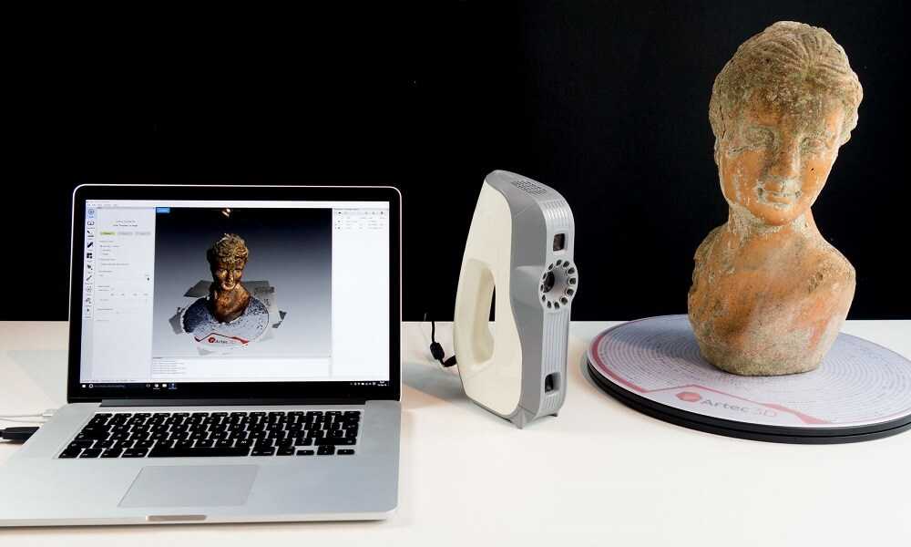
• Medium level: In many cases, the outline geometry plus dimensional accuracy will be enough to produce results for basic applications. Medium level resolution and quality allow some sizing and analysis and reveal defects at the edges of gross defects in a product.
• High level: Imperfections in surfaces and coating must be spotted and measured for metrology and quality control. The dimensional measurements are not only for outlining but must be precise and repeatable. Of course, this higher level of detail guides towards a different level of data quality than lower resolution 3D scanners.
Your specific application will dictate your requirements, with the level of detail and accuracy required having the most significant bearing on the cost of the system.
Versatility
Different scanners offer different levels of versatility in terms of applications, features, configurations, shapes, sizes and colors.
• Features: Budget scanners are great when you are just testing the water with 3D scanning. Handheld 3D scanners can be taken anywhere and offer a high degree of versatility and different applications. Higher-quality 3D scanners can be customized with automation to suit your application and increase throughput.
• Shapes and sizes: Many budget scanners can handle the basic scanning of large-scale objects such as construction connections, people or body parts, and large automotive components such as engine blocks. But they struggle with the smallest of objects in many instances. High-resolution stationary or automated 3D scanners are suitable for the smallest of objects with a high degree of customization on detailed sections, features, and measurements critical to quality control.
• Color and surface type: Many low-end 3D scanning systems will struggle with shiny or translucent materials. Some 3D scanners require sprays, spots or other identifiers added to the surface of an object, but a high-quality 3D scanner captures precise details without having to modify the surface.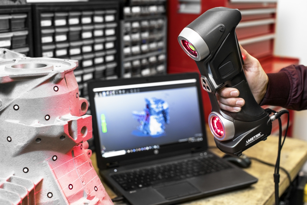 The ability to capture data from challenging surfaces is especially important for high-value components, where modifications or witness marks on surfaces are out of the question (such as jewelry or medical components).
ATOS Q offers the industry-leading standard for versatility and precision. This blue light 3D scanner captures high-definition, accurate and reliable data from objects of all sizes. Ideal for engineering, R&D and manufacturing, the ATOS Q is lightweight and portable (weighing only 4kg) and can be configured for manual or automated use.
Repeatability & Precision
The data quality your 3D scanner captures is impacted by how easily it is influenced by environmental disturbances during data acquisition. One example of an environmental disturbance that affects the quality of your measurement results comes from vibrations through the platform (or surface) upon which the component or 3D scanner is placed. A higher level of specification in your 3D scanner helps to reduce the vibration but also makes it more capable of filtering out disturbances.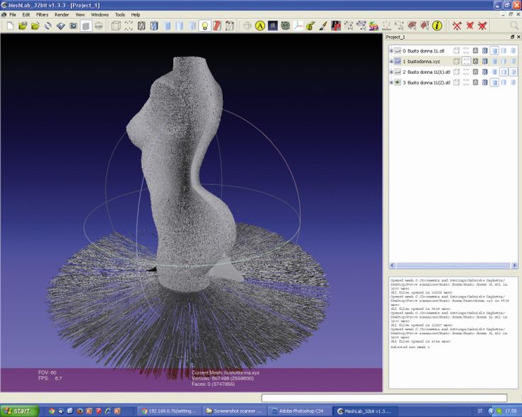
Budget devices can be useful for taking quick, partial scans of surfaces and shapes for contour analysis. In many quality control applications, the measurement process itself must be calibrated (or validated) and cannot vary, so an automated or semi-automated process of positioning and scanning is necessary. Where repeatability is required, the external vibrations and variations will require clamping in place, with precise, repeatable paths and movements of the 3D scanner.
GOM Scan 1 utilizes a stereo camera principle, allowing the sensor to recognize vibrations or disturbances during scanning. The 3D scanner compensates for the variation during scanning to produce a consistent result, regardless of the environment.
Choosing Stationary vs. Automated vs. Handheld for Small Objects
The type of positioning and support of the object you are trying to measure greatly affects the results your 3D scanner collects. There are three basic types of 3D scanning configurations to choose from:
1. Handheld
2. Stationary
3. Automation/Semi-automation
Handheld
Handheld scanners are great for objects like people and their features, cars and automotive components. Low-quality handheld scanners are notorious for losing their position during a scan (especially going around a corner). This issue results in the user having to stitch two scans together or restart the entire scan again.
High-quality handheld 3D scanners produce metrology-grade inspection data with no custom setups or platforms required for the object. The ZEISS T-SCAN hawk is an excellent example of a precision handheld scanner that can be taken anywhere and can switch between scanning modes at the touch of a button. This handheld 3D scanner also rapidly feeds your measurement data into GOM Software for analysis. Handheld scanners are the most portable 3D scanning option available. These can be easily taken outside for fieldwork in the open air. They are relatively easy to transport in a bag or case (compared to some larger and more built-in solutions).
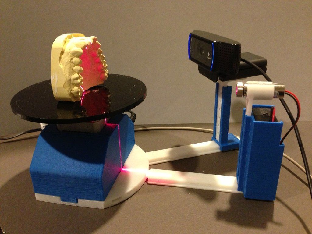
Stationary
Stationary 3D scanners hold the scanner in position, and the object rotates in front of it using a turn table. This setup can be more repeatable than scans from handheld scanners, as the object's movement is in one plane (rotation around a central axis), which leads to fewer opportunities for error.
Scans produced from stationary scanners are usually far superior to handheld scanners due to the control of the movement, resulting in finer details and higher resolution. Stationary scanners are larger than handheld units but are more portable than automated systems.
GOM Scan 1 is excellent for use as a stationary scanner. This highly portable 3D scanner is lightweight and provides industry-leading precision. Highly suitable for many small and medium-sized applications, GOM Scan 1 is a reliable tool for reverse engineering, quality control, research, art, 3D printing and more.
Automated and Semi-Automated
When using an automated 3D scanner, the object is held in place, and the relative movement of the scanner or the object (or both) is controlled by the system itself. The object can be passed in front of the scanner at different angles using different paths to precisely control the speed and motion. This highly repeatable process can be finely tuned for precise details on small components. This advantage is especially important for quality control environments where repeated measurements are compared over time for drift or changes from a baseline. These units generally take up more space than handheld or stationary scanners and aren't meant to be used as a portable solution. Automated 3D scanners are usually larger and require more preparation for moving or transporting to new locations due to their size and layout. Semi-automated systems work similarly to automated systems, but the scanning or the rotation is somewhat manual, requiring the user to rotate the platform or otherwise interact with the system to create a scan.
Measuring volume is an important factor when considering the best scanner for your application. Point clouds are the collection of individual points in space captured during a scan. These points in space are the boundaries of the object and its surface. The 3D scanning software uses these points to render the object's surface and create the digitized representation of the object that we see in the finished scan image.
Resolution is the distance between two points, with a lower distance between points giving richer detail in the end result. A greater number of points collected (a higher measuring volume) leads to higher resolution data. A high measuring volume and resolution are especially important when dealing with smaller objects because the ratio of the part's dimensions to the distance between the measurement point is much closer.
Higher measuring volume leads to more detailed data capture but also leads to large file sizes and slower rendering times. This problem is resolved when working with an advanced 3D metrology software solution such as GOM Software.
At the highest end of industry performance, ATOS 5 offers point-spacing down to 0.0236mm (the distance between two points on a scan). A single pass of this scanner captures up to 12 million measurement data points in as fast as 0.2 seconds per scan.
Find the Best 3D Scanner for the Small Objects You Work With
Contact a CAPTURE 3D team member to help you find the best 3D scanner for the small objects you work with. CAPTURE 3D carries various 3D scanners for small objects to fit your specific application. Schedule a demo of our accurate 3D scanning solutions or get a proof-of-concept to understand the benefits our technology brings to your components.
All about 3D scanners: from varieties to applications
The 3D scanner is a special device that analyzes a specific physical object or space in order to obtain data on the shape of an object and, if possible, its appearance (for example , about color). The collected data is then used to create a digital three-dimensional model of this object.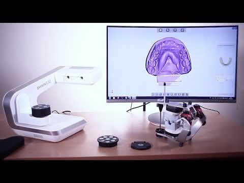
To create 3D-scanner allows several technologies at once, differing from each other in certain advantages, disadvantages, as well as cost. In addition, there are some restrictions on the objects that can be digitized. In particular, there are difficulties with objects that are shiny, transparent or have mirror surfaces. nine0005
Don't forget that 3D data collection is also important for other applications. So, they are needed in the entertainment industry to create films and video games. Also, this technology is in demand in industrial design, orthopedics and prosthetics, reverse engineering, prototyping, as well as for quality control, inspection and documentation of cultural artifacts.
Functionality
The purpose of the 3D Scanner is to create a point cloud of geometric patterns on the surface of an object. These points can then be extrapolated to recreate the shape of the object (a process called reconstruction). If color data were obtained, then the color of the reconstructed surface can also be determined. nine0005
3D scanners are a bit like regular cameras. In particular, they have a cone-shaped field of view, and they can only receive information from surfaces that have not been darkened. The difference between these two devices is that the camera transmits only information about the color of the surface that fell into its field of view, but the 3D scanner collects information about the distances on the surface, which is also in its field of view. Thus the "picture" obtained with of the 3D scanner, describes the distance to the surface at each point in the image. This allows you to determine the position of each point in the picture in 3 planes at once.
In most cases, one scan is not enough to create a complete model of the object. Several such operations are required. As a rule, a decent number of scans from different directions will be needed in order to obtain information about all sides of the object.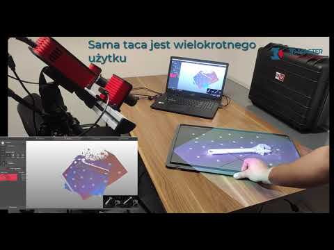 All scan results must be normalized to a common coordinate system, a process called image referencing or alignment, before a complete model is created. This whole procedure from a simple map with distances to a full-fledged model is called a 3D scanning pipeline. nine0005
Technology
There are several technologies for digitally scanning a mold and creating a 3D model of an object. However, a special classification has been developed that divides 3D scanners into 2 types: contact and non-contact. In turn, non-contact 3D scanners can be further divided into 2 groups - active and passive. Several technologies can fall under these categories of scanning devices.
Coordinated-measuring machine with two fixed mutually perpendicular measuring hands
Contact 3D scanners
Contact 3D-scanners Explore (probes) the object directly through physical contact, while the subject itself is expected to explode itself on a precision surface plate, ground and polished to a certain degree of surface roughness.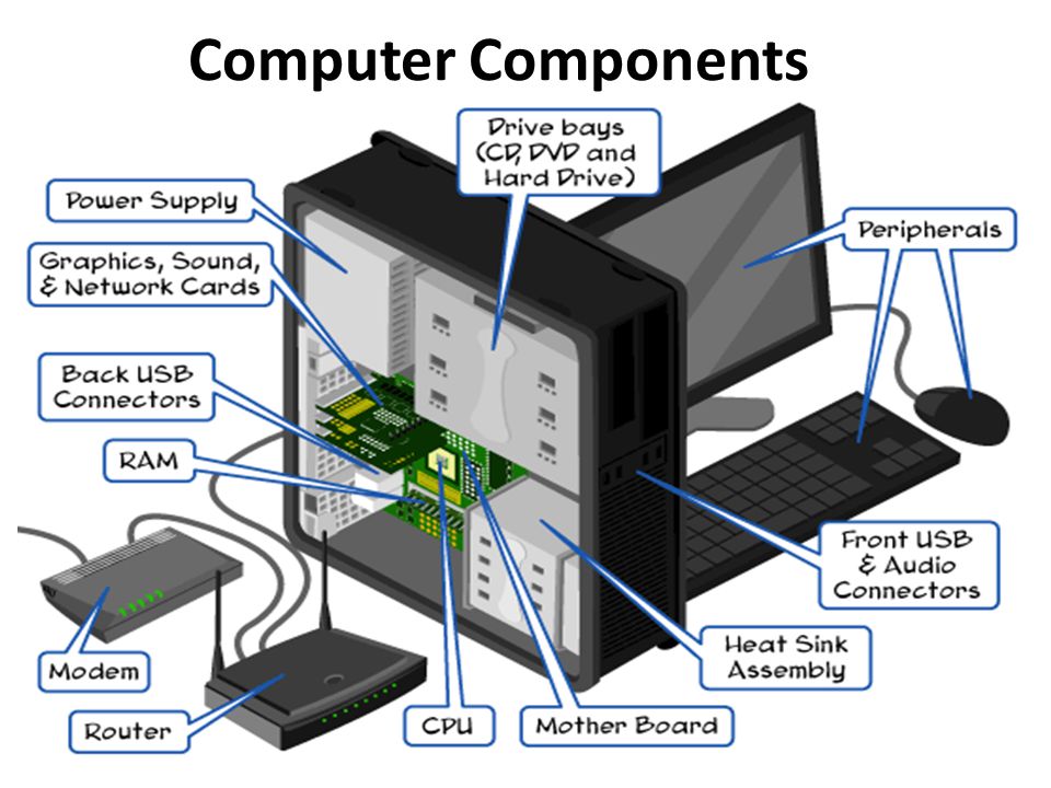 If the scanned object is uneven or cannot lie stably on a horizontal surface, then a special vise will hold it. nine0005
The scanner mechanism comes in three different forms:
- Carriage with a fixed measuring arm positioned perpendicularly, and measurement along the axes occurs while the arm slides along the carriage. This system is optimal for flat or regular convex curved surfaces.
- Fixed component manipulator with high precision angle sensors. The location of the end of the measuring arm entails complex mathematical calculations regarding the angle of rotation of the wrist joint, as well as the angle of rotation of each of the joints of the arm. This mechanism is ideal for probing recesses or interior spaces with a small inlet. nine0072
- Simultaneous use of the previous two methods. For example, a manipulator can be combined with a carriage, which allows you to get 3D data from large objects that have internal cavities or overlapping surfaces.
 The
The
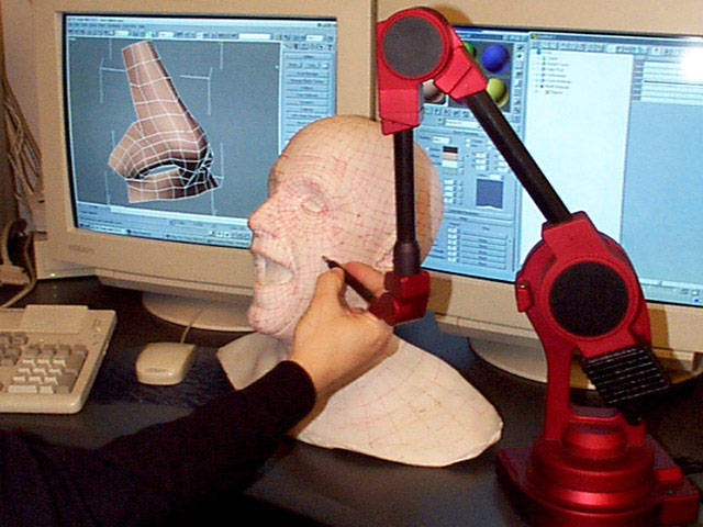
CMM (coordinate measuring machine) is a prime example of the contact 3D scanner . They are used mainly in manufacturing and can be ultra-precise. The disadvantages of CMM include the need for direct contact with the surface of the object. Therefore, it is possible to change the object or even damage it. This is very important if thin or valuable items such as historical artifacts are being scanned. Another disadvantage of CMM over other scanning methods is slowness. Moving the measuring arm with the probe in place can be very slow. The fastest result of CMM operation does not exceed a few hundred hertz. At the same time, optical systems, for example, a laser scanner, can operate from 10 to 500 kHz. nine0005
Another example is hand-held measuring probes used to digitize clay models for computer animation.
The Lidar device is used to scan buildings, rocks, etc., which makes it possible to create 3D models of them. The Lidar laser beam can be used in a wide range: its head rotates horizontally, and the mirror moves vertically.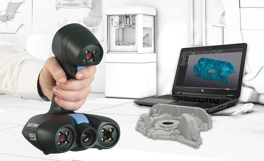 The laser beam itself is used to measure the distance to the first object in its path. nine0004
Non-contact active scanners
Active scanners use certain types of radiation or just light and scan an object through the reflection of light or the passage of radiation through an object or medium. These devices use light, ultrasound, or x-rays.
Time-of-Flight Scanners
Time-of-Flight Laser Scanner The 3D scanner is an active scanner that uses a laser beam to examine an object. This type of scanner is based on a time-of-flight laser range finder. In turn, the laser rangefinder determines the distance to the surface of the object, based on the time of flight of the laser back and forth. The laser itself is used to create a pulse of light, while the detector measures the time until the light is reflected. Given that the speed of light (c) is a constant value, knowing the time of flight of the beam back and forth, you can determine the distance over which the light has moved, it will be twice the distance between the scanner and the surface of the object. If (t) is the round-trip flight time of the laser beam, then the distance will be (c*t\2). Laser beam time-of-flight accuracy of the 3D scanner depends on how accurately we can measure time (t) itself: 3.3 picoseconds (approximately) is needed for the laser to travel 1 millimeter.
The laser distance meter determines the distance of only one point in a given direction. Therefore, the device scans its entire field of view in separate points at a time, while changing the direction of scanning. You can change the direction of the laser rangefinder either by rotating the device itself, or using a system of rotating mirrors. The latter method is often used, because it is much faster, more accurate, and also easier to handle. For example, time-of-flight 3D scanners can measure distance from 10,000 to 100,000 points in one second.
TOF devices are also available in 2D configuration. Basically, this applies to time-of-flight cameras. Triangulation scanners Two positions of the object are shown.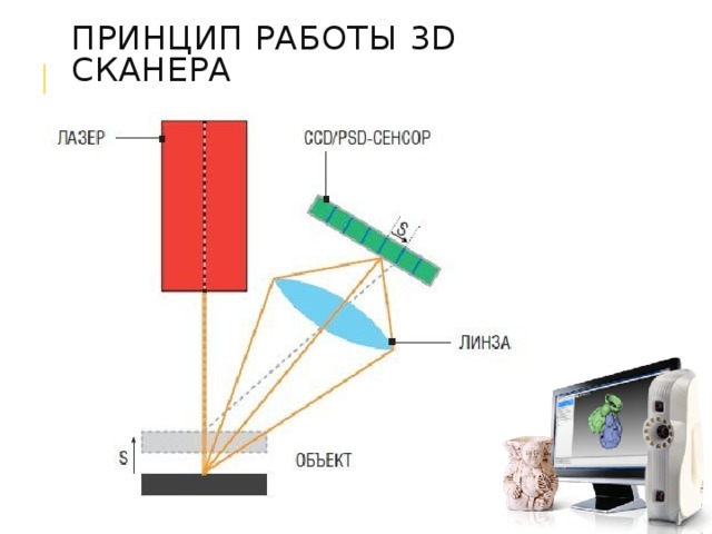
A point cloud is generated by triangulation and a laser stripe. nine0004
Triangulation laser scanners The 3D scanners are also active scanners that use a laser beam to probe an object. Like the time-of-flight 3D scanners, triangulation devices send a laser to the scanned object, and a separate camera captures the location of the point where the laser hit. Depending on how far the laser travels across the surface, the dot appears at different locations in the camera's field of view. This technology is called triangulation because the laser dot, the camera and the laser emitter itself form a kind of triangle. The length of one side of this triangle is known - the distance between the camera and the laser emitter. The angle of the laser emitter is also known. But the camera angle can be determined by the location of the laser dot in the field of view of the camera. These 3 indicators completely determine the shape and size of the triangle and indicate the location of the corner of the laser point.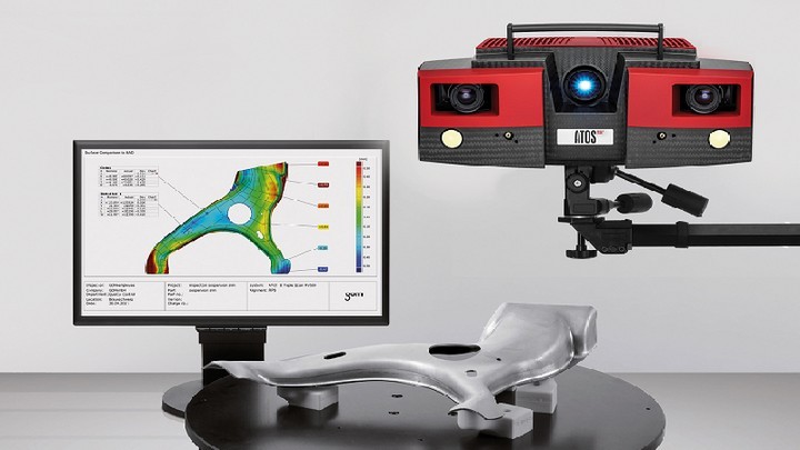 In most cases, to speed up the process of obtaining data, a laser strip is used instead of a laser dot. Thus, the National Research Council of Canada was among the first scientific organizations that developed the basics of triangulation laser scanning technology back in 1978 year.
Advantages and disadvantages of
scanners Both time-of-flight and triangulation scanners have their own strengths and weaknesses, which determines their choice for each specific situation. The advantage of time-of-flight devices is that they are optimally suited for operation over very long distances up to several kilometers. They are ideal for scanning buildings or geographic features. At the same time, their disadvantages include measurement accuracy. After all, the speed of light is quite high, so when calculating the time it takes for the beam to overcome the distance to and from the object, some flaws (up to 1 mm) are possible. And this makes the scan results approximate. nine0005
As for triangulation rangefinders, the situation is exactly the opposite. Their range is only a few meters, but the accuracy is relatively high. Such devices can measure distance with an accuracy of tens of micrometers.
The study of the edge of an object negatively affects the accuracy of the TOF scanners. The laser pulse is sent one, and is reflected from two places at once. The coordinates are calculated based on the position of the scanner itself, and the average value of the two reflections of the laser beam is taken. This causes the point to be defined in the wrong place. When using scanners with high resolution, the chances that the laser beam hits the exact edge of the object increase, but noise will appear behind the edge, which will negatively affect the scan results. Scanners with a small beam can solve the edge scanning problem, but they have limited range, so the beam width will exceed the distance. There is also special software that allows the scanner to perceive only the first reflection of the beam, while ignoring the second.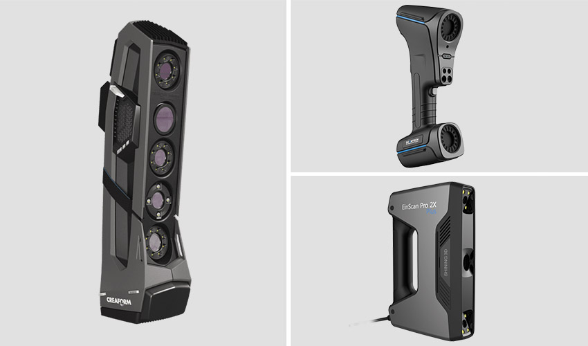 nine0005
At 10,000 dots per second, low resolution scanners can do the job within seconds. But for scanners with high resolution, you need to do several million operations, which will take minutes. It should be borne in mind that the data may be distorted if the object or the scanner moves. So, each point is fixed at a certain point in time in a certain place. If the object or scanner moves in space, then the scan results will be false. That's why it's so important to mount both the object and the scanner on a fixed platform and keep the possibility of vibration to a minimum. Therefore, scanning objects in motion is practically impossible. Recently, however, there has been active research on how to compensate for the effect of vibration on data corruption. nine0005
It is also worth considering that when scanning in one position for a long time, a slight movement of the scanner may occur due to temperature changes. If the scanner is mounted on a tripod and one side of the scanner is exposed to strong sunlight, then the tripod will expand and the scan data will gradually distort from one side to the other. However, some laser scanners have built-in compensators that counteract any movement of the scanner during operation. nine0005
Conoscopic holography
In the conoscopic system, a laser beam is projected onto the surface of an object, after which the beam is reflected along the same path, but through a conoscopic crystal, and is projected onto a CCD (charge-coupled device). The result is a diffraction pattern from which frequency analysis can be used to determine the distance to the surface of an object. The main advantage of conoscopic holography is that only one beam path is needed to measure the distance, which makes it possible to determine, for example, the depth of a small hole. nine0005
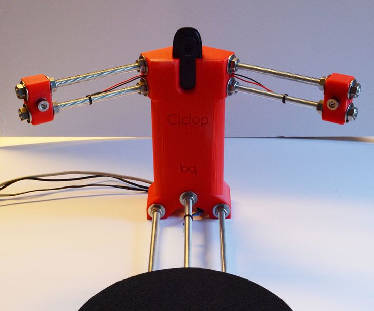
Handheld laser scanners
Handheld laser scanners create a 3D image using the triangulation principle described above. A laser beam or stripe is projected onto an object from a hand-held emitter, and a sensor (often a CCD or position-sensitive detector) measures the distance to the surface of the object. The data is collected relative to the internal coordinate system and therefore, to obtain results, if the scanner is in motion, the position of the device must be accurately determined. This can be done using basic features on the scanned surface (adhesive reflective elements or natural features) or using the external tracking method. The latter method often takes the form of a laser tracker (providing a position sensor) with a built-in camera (to determine the orientation of the scanner). You can also use photogrammetry, provided by 3 cameras, which gives the scanner six degrees of freedom (the ability to make geometric movements in three-dimensional space). Both techniques typically use infrared LEDs connected to the scanner. They are observed by cameras through filters that ensure the stability of ambient lighting (reflecting light from different surfaces). nine0005
Scan data is collected by a computer and recorded as points in 3D space, which after processing are converted into a triangulated grid. The computer-aided design system then creates a model using a non-uniform rational B-spline, NURBS (a special mathematical form for creating curves and surfaces). Handheld laser scanners can combine this data with passive visible light sensors that capture surface texture and color to create or reverse engineer a complete 3D Models .
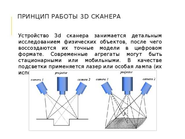
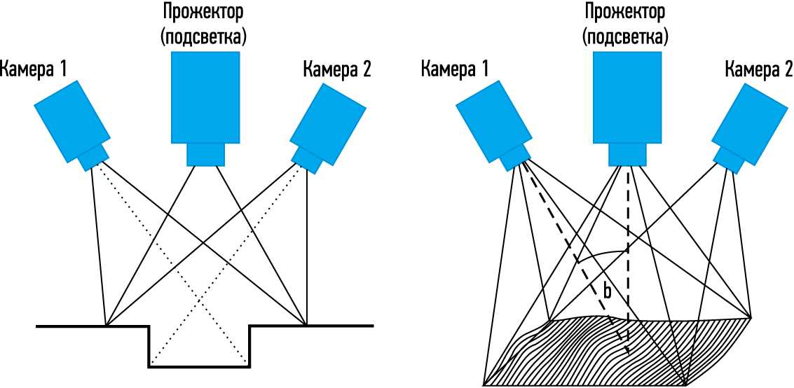
Structured light
3D scanners, working on structured light technology, represent a projection of a light grid directly onto an object, deformation of this pattern and is a model of the scanned object. The grid is projected onto the object using a liquid crystal projector or other constant light source. A camera positioned just to the side of the projector captures the shape of the network and calculates the distance to each point in the field of view. nine0113 Structured light scanning is still an active area of research, with quite a few research papers devoted to it each year. Ideal maps are also recognized as useful as structured light patterns that can solve matching problems and allow errors to be corrected as well as detected.
The advantage of the Structured Light 3D Scanners is their speed and accuracy. Instead of scanning one point at a time, structured scanners scan several points at the same time or the entire field of view at once. Scanning the entire field of view takes a fraction of a second, and the generated profiles are more accurate than laser triangulations. This completely solves the problem of data corruption caused by motion. In addition, some existing systems are capable of scanning even moving objects in real time. For example, the VisionMaster, a 3D scanning system, has a 5-megapixel camera, so each frame contains 5 million dots. nine0005
Real-time scanners use digital edge projection and a phase-shifting technique (one of the techniques for using structured light) to capture, reconstruct and create a high-density computer model of dynamically changing objects (such as facial expressions) at 40 frames per second. A new type of scanner has recently been created. Various models can be used in this system. The frame rate for capturing and processing data reaches 120 frames per second. This scanner can also process individual surfaces. For example, 2 moving hands. Using the binary defocusing method, the shooting speed can reach hundreds or even thousands of frames per second. nine0005
Modulated light
When using the 3D scanners based on modulated light, the light beam directed at the object is constantly changing. Often the change of light passes along a sinusoid. The camera captures the reflected light and determines the distance to the object, taking into account the path that the light beam has traveled. Modulated light allows the scanner to ignore light from sources other than the laser, thus avoiding interference. nine0005
Volumetric techniques
Medical
Computed tomography (CT) is a special medical imaging technique that creates a series of two-dimensional images of an object, a large three-dimensional image of the internal space. Magnetic resonance imaging works on a similar principle - another imaging technique in medicine, which is distinguished by a more contrast image of the soft tissues of the body than CT. Therefore, MRI is used to scan the brain, the musculoskeletal system, the cardiovascular system, and to search for oncology. These techniques produce volumetric voxel models that can be rendered, modified, and transformed into a traditional 3D surface using isosurface extraction algorithms. nine0005
Production
Although MRI, CT or microtomography are more widely used in medicine, they are also actively used in other areas to obtain a digital model of an object and its environment. This is important, for example, for non-destructive testing of materials, reverse engineering or the study of biological and paleontological samples.
Non-contact passive scanners
Passive scanners do not emit light, instead they use reflected light from the environment. Most scanners of this type are designed to detect visible light, which is the most accessible form of ambient radiation. Other types of radiation, such as infrared, may also be involved. Passive scanning methods are relatively cheap, because in most cases they do not need special equipment, a conventional digital camera is enough. nine0113 Stereoscopic systems involve the use of 2 video cameras located in different places, but in the same direction. By analyzing the differences in the images of each camera, you can determine the distance to each point in the image. This method is similar in principle to human stereoscopic vision.
Photometric systems typically use a single camera that captures multiple frames in all lighting conditions. These methods attempt to transform the object model in order to reconstruct the surface for each pixel. nine0005
Silhouette techniques use contours from successive photographs of a three-dimensional object against a contrasting background. These silhouettes are extruded and transformed to get the visible skin of the object.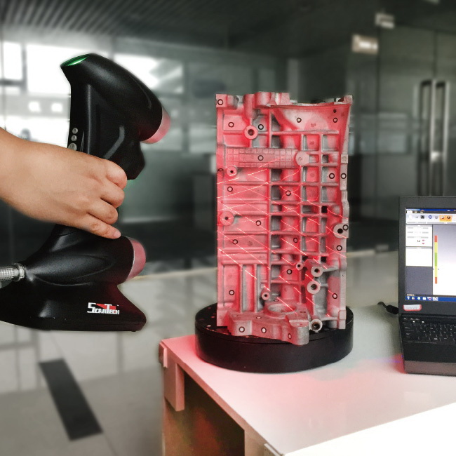 However, this method does not allow you to scan the recesses in the object (for example, the inner cavity of the bowl).
There are other methods that are based on the fact that the user himself discovers and identifies some features and shapes of the object, based on many different images of the object, which allow you to create an approximate model of this object. Such methods can be used to quickly create a three-dimensional model of objects of simple shapes, for example, a building. You can do this using one of the software applications: D-Sculptor, iModeller, Autodesk ImageModeler or PhotoModeler. nine0005
This 3D scan is based on the principles of photogrammetry. In addition, this technique is in some ways similar to panoramic photography, except that the photographs of the object are taken in three-dimensional space. Thus, it is possible to copy the object itself, rather than taking a series of photos from one point in three-dimensional space, which would lead to the reconstruction of the object's environment.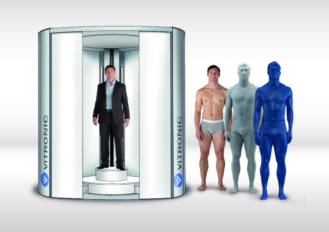
Reconstruction
From point clouds
The point clouds generated by the 3D Scanners can be directly used for measurement or visualization in architecture and engineering.
However, most applications use non-homogeneous rational B-spline, NURBS, or editable CAD models (also known as solid models) instead of polygonal 3D models.
- Polygon mesh models: In polygon representation shapes curved surfaces consist of many small flat surfaces with edges (a striking example is a ball in discotheques). Polygonal models are very in demand for visualization in the field of CAM - an automated system for technological preparation of production (for example, mechanical processing). At the same time, such models are quite « heavy" (accommodate a large amount of data) and are quite difficult to edit in this format. Reconstruction into a polygonal model involves searching and combining neighboring points with straight lines until a continuous surface is formed.
 For this, you can use a number of paid and free programs (MeshLab, Kubit PointCloud for Au toCAD, 3D JRC Reconstructor, ImageModel, PolyWorks, Rapidform, Geomagic, Imageware, Rhino 3D, etc.). nine0072
 - Surface models: This method represents the next level of sophistication in the field of modeling. It applies a set of curved surfaces that give your object its shape. It can be NURBS, T-Spline or other curved objects from the topology. Using NURBS converts, for example, a sphere to its mathematical equivalent. Some applications require manual processing of the model, but more advanced programs also offer automatic mode. This option is not only easier to use, but also provides the ability to modify the model when exporting to a computer-aided design system (CAD). Surface models are editable, but only in a sculptural way. Organic and artistic forms lend themselves well to modeling. Surface modeling is available in Rapidform, Geomagic, Rhino 3D, Maya, T Splines. nine0072
- 3D CAD Models: From an engineering and manufacturing perspective, this type of simulation is a full digitized form of a parametric CAD model.
 After all, CAD is the industry's common "language" for describing, editing, and preserving the shape of an enterprise's assets. For example, in CAD, a sphere can be described by parametric functions that are easy to edit by changing their value (say, radius or center point).
These CAD models don't just describe the shell or shape of an object, but they also enable design intent (ie, critical features and their relationship to other features). An example of design intent that is not expressed in form would be the ribbed bolts of a brake drum, which should be concentric with the hole in the center of the drum. This nuance determines the sequence and method of creating a CAD model, so the engineer, taking into account these features, will develop bolts tied not to the outer diameter, but, on the contrary, to the center. Thus, to create such a CAD model, you need to correlate the shape of the object with the design intent. nine0005
There are several approaches to get a parametric CAD model. Some involve only exporting a NURBS surface, leaving the CAD engineer to complete the modeling (Geomagic, Imageware, Rhino 3D). Others use the scan data to create an editable and verifiable function model that can be fully imported into CAD with an intact fully functional tree, providing a complete fusion of shape and design intent of the CAD model (Geomagic, Rapidform). However, other CAD applications are powerful enough to manipulate a limited number of points or polygonal models in a CAD environment (CATIA, AutoCAD, Revit). nine0005
From the 2D slice set
3D reconstruction of the brain or eyeballs based on CT results is performed using DICOM images. Their peculiarity is that the areas on which air is displayed, or bones with a high density are made transparent, and the sections are superimposed in a free alignment interval. The outer ring of biomaterial surrounding the brain is made up of the soft tissues of the skin and muscles on the outside of the skull.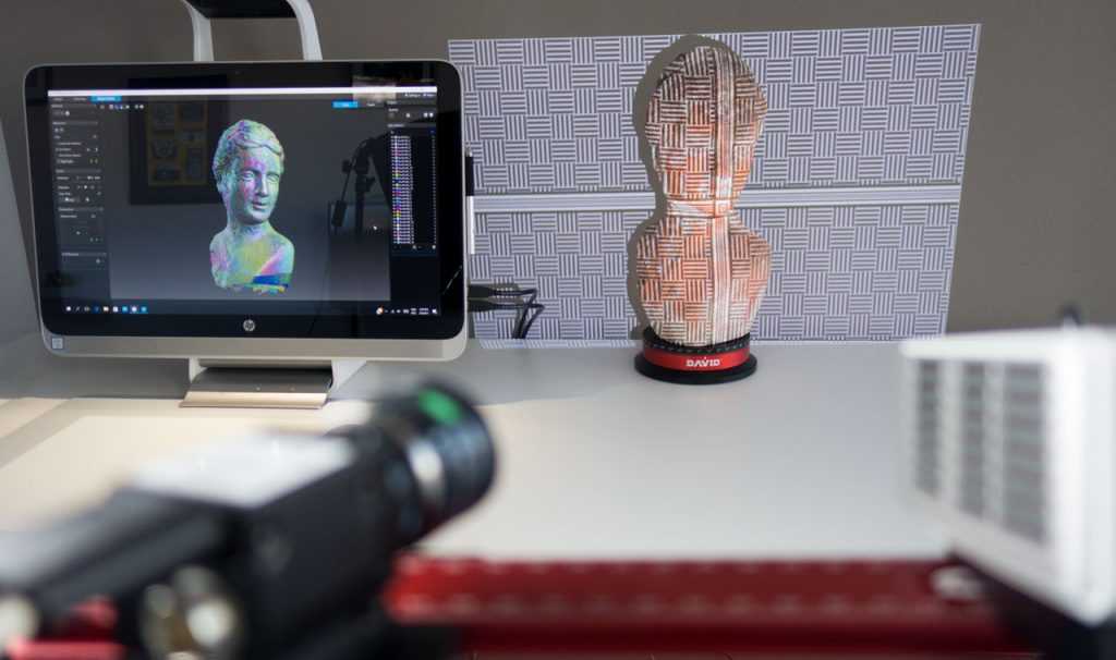 All sections are made on a black background. Since they are simple 2D images, when added one-to-one when viewed, the borders of each slice disappear due to their zero thickness. Each DICOM image is a slice about 5 mm thick. nine0004
CT, industrial CT, MRI or microCT scanners do not create a point cloud, but 2D slices (referred to as a “tomogram”) that are superimposed on each other, resulting in a kind of 3D model. There are several ways to do this, depending on the desired result:
- Volume rendering: Different parts of an object usually have different thresholds and grayscale densities. Based on this, a three-dimensional model can be freely designed and displayed on the screen. Several models can be made from different thresholds, allowing different colors to represent a specific part of an object. Volumetric rendering is most often used to render a scanned object. nine0072
- Image segmentation: When different structures have similar threshold or midtone values, it may not be possible to separate them simply by changing volume rendering parameters.
 The solution to the problem will be segmentation - a manual or automatic procedure that will remove unnecessary structures from the image. Special programs that support image segmentation allow you to export segmented structures to CAD or STL format, which will allow you to continue working with them. nine0072
 - Meshing based on image analysis: When 3D image data (CFD and FEA) is used for computer analysis, simple data segmentation and meshing from a CAD file can be quite time consuming. In addition, some typical image data may not be inherently suitable for a complex topology. The solution lies in image analysis meshing, which is an automated process for generating an accurate and realistic geometric description of the scanned data. nine0072
Application
Material Handling and Manufacturing
3D Laser Scanning describes a general way to measure or scan a surface using laser technology. It is used in several areas at once, differing mainly in the power of the lasers that are used and the results of the scan itself.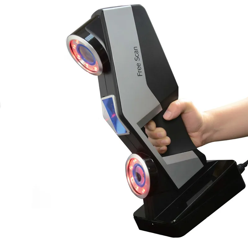 Low laser power is needed when the scanned surface should not be influenced, for example, if it only needs to be digitized. Confocal or 3D laser scanning are methods that provide information about the scanned surface. Another low power application involves a projection system that uses structured light. It is applied to solar panel plane metrology involving voltage calculation with a throughput of more than 2,000 plates per hour. nine0005
The laser power used for laser scanning of industrial equipment is 1W. The power level is typically 200mW or less.
Construction industry
- Robot control: laser scanner acts as the eye of the robot
- Executive drawings of bridges, industrial plants, monuments
- Documentation of Historic Sites
- Site modeling and layout
- Quality control
- Measurement of works
- Reconstruction of highways
- Marking an existing shape/state to identify structural changes after extreme events - earthquake, ship or truck impact, fire.
- Creation of GIS (Geographic Information System), maps and geomatics
- Scanning of subsurface in mines and karst voids
- Court records
Benefits of 3D scanning
Creating a 3D model by scanning has the following benefits:
- Makes working with complex parts and shapes more efficient
- Encourages product design when needed to add a part created by someone else.
- If CAD models become outdated, 3D scanning will provide an updated version
- Replaces missing or missing parts of
Entertainment
3D scanners are widely used in the entertainment industry to create 3D digital models in film and video games. If the model being created has a counterpart in the real world, then scanning will allow you to create a three-dimensional model much faster than developing the same model through 3D modeling. Quite often, artists first sculpt a physical model, which is then scanned to get a digital equivalent, instead of creating such a model on a computer. nine0005
Reverse engineering
Reverse engineering of mechanical components requires a very accurate digital model of the objects to be recreated. This is a good alternative to converting many points of a digital model to a polygon mesh, using a set of NURBS flat and curved surfaces, or, ideally for mechanical components, creating a 3D CAD model. A 3D scanner can be used to digitize objects that freely change shape. As well as the prismatic configuration, for which a coordinate measuring machine is usually used. This will allow you to determine the simple dimensions of the prismatic model. This data is further processed by special programs for reverse engineering. nine0005
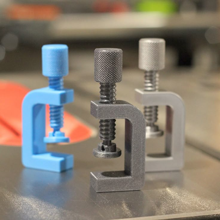
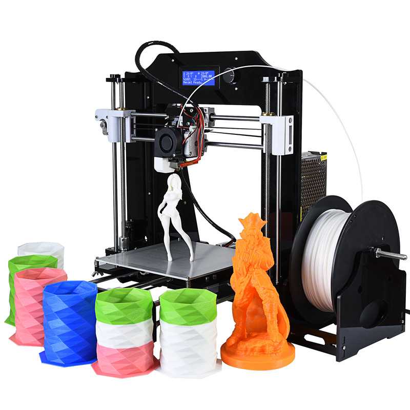
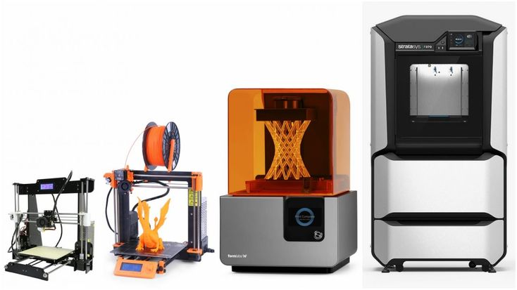
3D printing
3D scanners are also actively used in the field of 3D printing, as they allow you to create fairly accurate 3D models of various objects and surfaces in a short time, suitable for further refinement and printing. In this area, both contact and non-contact scanning methods are used, both methods have certain advantages.
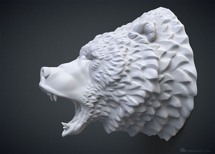
Cultural heritage
An example of copying a real object through 3D scanning and 3D printing. There are many research projects that have been carried out using the scanning of historical sites and artifacts to document and analyze them. The combined use of 3D scanning and 3D printing makes it possible to replicate real objects without the use of a traditional plaster cast, which in many cases can damage a valuable or delicate cultural heritage artifact. The sculpture of the figure on the left was digitized using a 3D scanner, and the resulting data was converted in the MeshLab program. The resulting digital 3D model was printed using a rapid prototyping machine that allows you to create a real copy of the original object. nine0004
Michelangelo
There are many research projects that have been carried out using scanning of historical sites and artifacts to document and analyze them.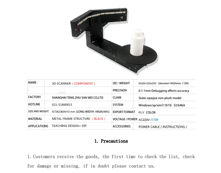
In 1999, 2 different research groups started scanning Michelangelo's statues. Stanford University, along with a team led by Mark Levoy, used a conventional laser triangulation scanner built by Cyberware specifically to scan Michelangelo's statues in Florence. In particular, the famous David, "Slaves" and 4 more statues from the Medici chapel. Scanning is performed with a dot density of 0.25 mm, sufficient to see the traces of Michelangelo's chisel. Such a detailed scan involves obtaining a huge amount of data (about 32 gigabytes). It took about 5 months to process them. nine0005
Around the same time, a research group from IBM was working, led by H. Raschmeyer and F. Bernardini. They were tasked with scanning the Florentine Pieta sculpture to obtain both geometric data and color information. The digital model obtained from a Stanford University scan was fully used in 2004 to further restore the statue.
Medical applications CAD/CAM
3D scanners are widely used in orthopedics and dentistry to create a 3D patient shape. Gradually, they replace the outdated gypsum technology. CAD/CAM software is used to create prostheses and implants.
Many dentistry uses CAD/CAM as well as 3D scanners to capture the 3D surface of a dentifrice (in vivo or in vitro) in order to create a digital model using CAD or CAM techniques (e.g. , for a CNC milling machine (computer numerical control), as well as a 3D printer). Such systems are designed to facilitate the process of 3D scanning of the drug in vivo with its further modeling (for example, for a crown, filling or inlay). nine0005
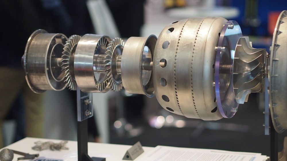
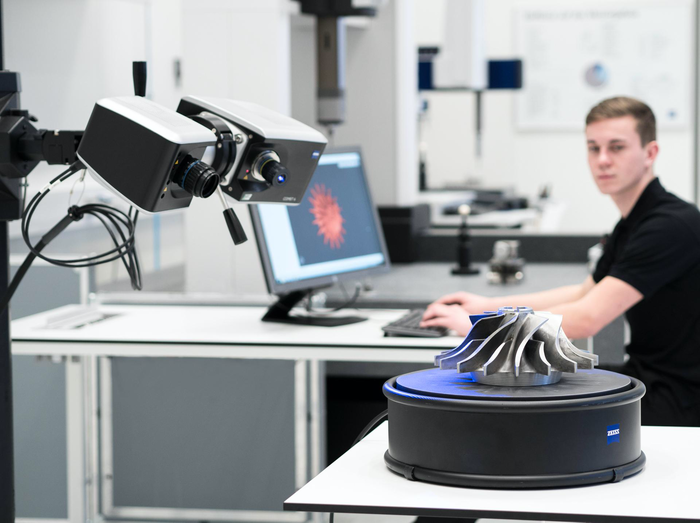
Quality assurance and industrial metrology
The digitization of real world objects is of great importance in various fields of application. 3D scanning is very actively used in industry to ensure product quality, for example, to measure geometric accuracy. Predominantly all industrial processes such as assembly are quite complex, they are also highly automated and are usually based on CAD (computer-aided design data). The problem is that the same degree of automation is required for quality assurance. A striking example is the automated assembly of modern cars, because they consist of many parts that must match exactly with each other. nine0113 Optimum performance levels are guaranteed by quality assurance systems. Geometrical metal parts need special checking, because they must be of the correct size, fit together to ensure reliable operation.
In highly automated processes, the results of geometric measurements are transferred to machines that produce the corresponding objects. Due to friction and other mechanical processes, the digital model may differ slightly from the real object. In order to automatically capture and evaluate these deviations, the manufactured parts must be rescanned. For this, 3D scanners are used, which create a reference model with which the received data are compared. nine0113 The process of comparing 3D data and CAD model is called CAD comparison, and can be a useful method for determining mold and machine wear, final assembly accuracy, gap analysis, and the volumetric surface of a disassembled part. Currently laser triangulation scanners, structured light devices and contact scanning are the leading technologies used in industrial applications. Contact scanning methods, although they are the slowest, but the most accurate option. nine0005
If you have a need for 3D scanning services and / or subsequent reverse engineering, please contact us at [email protected].
technologies, types, how 3D devices work
Many digital engineering strategies for the future of design, manufacturing, quality control, and product release begin with 3D scanning. 3D scanners work with advanced technologies and specialized software to create a tool that allows you to achieve revolutionary results. For those still working with power tools and traditional coordinate measuring machine (CMM) technology, 3D scanners serve as an easy gateway to advanced manufacturing and engineering strategies. nine0005
Read below to learn more about how 3D scanners work and what the technology can do so you can start enjoying its benefits now.![]()
What are 3D scanners?
A 3D scanner works by capturing data from the surface of a physical object to describe its shape in an accurate digital 3D format. Unlike CMM measurement data, high quality 3D scan data is used for more than just inspection and dimensional analysis. The data obtained by non-contact measurement allows faster and more accessible digital analysis and inspection using a visual, in-depth method of examination. nine0113 3D scanners are also used to replicate parts in reverse engineering, check the fit, shape and function of components in remote locations, and check CAD models of 3D printed parts. 3D printers can use 3D scan data to create physical objects.
What is 3D scanning?
3D scanning is the process of collecting data about the surface of an object in digital format to determine its shape, allowing users to either reproduce the part by reverse engineering or verify it by dimensional analysis. nine0005
To do this, operators use scanners that use lasers, light or sensors to determine the surface of the scanned object and assign data points to this surface. These data points will eventually recreate the . Depending on the type of laser, light, or sensor used, the level of detail and scanning performance may vary.
3D Scanning Technologies
Photogrammetry
Originating from photography, photogrammetry is an incredibly useful technology in various fields. This technology allows you to take multiple images taken at different positions and triangulate points on those images to determine their location in 3D space. nine0005
For example, cartographers use this technology when compiling maps. When it comes to hard-to-reach places like mountains, surveyors can use photogrammetry to take measurements.
Many modern technologies use photogrammetry, and the quality of the images is the main factor determining accuracy. If the images are poor quality, there will be holes in the grid. The more images you can get, the higher the scan accuracy will be. nine0005
Shining 3D offers a solution - DigiMetric Photogrammetric System.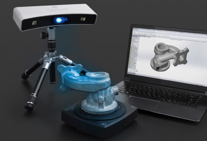
Read also DigiMetric case study “Scanning with a Digimetric Photogrammetric System and a FreeScan Handheld 3D Laser Scanner”
Structured Light
This technology is created by applying geometric patterns to an object while simultaneously capturing an image with a camera. In this case, the camera registers the deviation of the image.
Based on this template offset, all existing points can be located. It is necessary to conduct many scans from different positions, and then merge them until the mesh is 100% complete. Computer programs automatically combine all images to form a complete grid. nine0005
3D laser scanning method
3D laser scanning data acquisition
3D laser scanning process
The object to be laser scanned is placed on the scanner platform. Specialized software directs the laser probe over the surface of the object. A laser probe projects a line of laser light onto the surface, and 2 sensor cameras continuously record the change in distance and shape of the laser line in three dimensions (XYZ) as it passes along the object. nine0005
Acquired data
The shape of an object is displayed as millions of dots, called “point clouds”, on a computer monitor as the laser moves around, capturing the entire shape of the object's surface. The process is very fast and laser scanning is more accurate than infrared.
Point cloud data for inspection
If the data is to be used for inspection, the scanned object can be compared with the designer's nominal CAD data. The result of this comparison is provided as a “color map deviation report” in PDF format, which clearly describes the differences between scanned data and CAD data. nine0005
Reverse engineering CAD model
Laser scanning is the fastest, most accurate and automated way to obtain digital 3D data for reverse engineering. Again, with the help of specialized software, point cloud data is used to create a 3D CAD model of the geometry of the part.
The CAD model can accurately reproduce the scanned object, or the object can be modified in the CAD model to correct imperfections.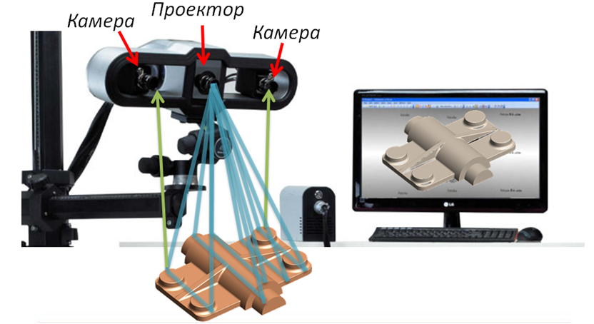 nine0005
Types of 3D scanners
Active scanners emit some radiation or light. The scanner detects the reflection to collect information about the object. Let's take a look at the active views of 3D scanners below.
3D Laser Scanners
3D Laser Scanners use a process called trigonometric triangulation to accurately display a 3D shape as millions of dots. Laser scanners work by projecting a laser line or lines onto an object and then capturing its reflection using one or more sensors. nine0005
The sensors are located at a known distance from the laser source. Accurate point measurements can be made by calculating the angle of reflection of the laser light.
Laser scanners are very popular and come in many designs. These include handheld, manipulator-based, CMM-based handheld devices, long-range trackers, and long-range single-point trackers.
Benefits of 3D laser scanners:
- Ability to scan complex surfaces such as shiny or dark surfaces.
 nine0072
 - Less sensitive to changing lighting conditions and ambient light.
- The obtained data is more accurate, available for inspection.
Learn about FreeScan UE 3D laser scanner features, features, features and benefits.
An example of using FreeScan UE and photogrammetry can be found on our blog page - 3D Inspection of Large Parts.
As well as the article The rebirth of historic motorsport icons. nine0005
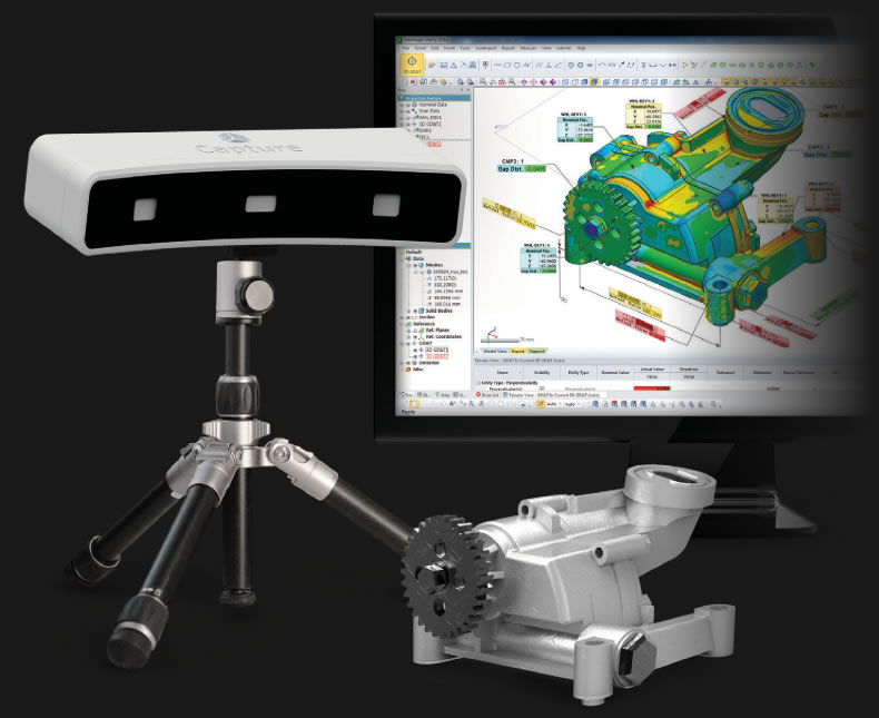
Projected or structured light 3D scanners
Historically known as “white light” 3D scanners, most structured light 3D scanners today use blue or white LED projected light. These 3D scanners project a pattern of light onto an object, consisting of stripes, blocks, or other shapes. A 3D scanner has one or more sensors that look at the edges of these patterns or structural shapes to determine the object's 3D shape.
Using the same trigonometric triangulation method as in laser scanners, so the distance from the sensors to the light source is known. Structured light scanners can be mounted on a tripod or hand held. nine0005
Benefits of Structured Light 3D Scanners:
- Very fast scan times of only 2 seconds per scan.
- Versatility - multiple lenses for scanning small and large parts in one system.
- Portability - handheld systems are highly mobile.
- Eye friendly for 3D scanning of people and animals.
- 3D color scans available.
- Various price ranges from inexpensive to expensive depending on resolution and accuracy. nine0072
Excellent solutions of 3D scanners with structured light, are models:
- EINSCAN HX
- manual 3D scanner EINSCAN H.
Examples of scanning using 3D 3D scanners EINSCAN:
- HTTPS: // www.shining3d.ru/blog/perfectly-equipped-for-emergency-with-the-einscan-hx/
- https://www.shining3d.ru/blog/at-the-intersection-of-craftsmanship-and- technology-einscan-h-and-fusion-360-in-traditional-boat-building/.
 nine0072
Coordinate Measuring Machine (CMM)
Coordinate Measuring Machine (CMM) is mainly used for parts inspection. The machine can be controlled manually or through autonomous control by software and computers. Measurements are determined by attaching a sensor to the machine. The sensor usually has a small ball at the end of a shaft of known diameter. The CMM is then programmed to make contact with the part. When the machine senses contact with the probe tip, a value in XYZ space is measured. The most common type of CMM is the bridge type, which has 3 x, y, and z axes. The attached sensor system can be rotated to provide an additional 3 xyz axes, giving a total of 6 degrees of freedom (DOF). nine0113 For very accurate part measurements down to a few microns, CMMs are usually installed in a controlled room.
The room includes a reinforced floor, controlled humidity and temperature, and isolation from vibration and other forces that may affect accuracy.
In addition, most CMMs have a large granite table surface that is perfectly flat.