3D printing large flat objects
How to 3D Print Models Larger than Your 3D Printer’s Build Volume
Don’t own a large format 3D printer yet? When determining what’s possible with a compact desktop 3D printer, think beyond the build volume. Just as assemblies such as your smartphone or even a road bridge consist of many individual building blocks, splitting a model into smaller parts that can be combined after printing is a great solution for 3D printing large objects that don’t fit on a build platform.
Splitting a part can also be the best way to get a high-quality result, even if the whole part could fit into a single build. This is the case when multiple or opposing surfaces need to be free of support marks, a design has complex overhangs, or a model contains cavities that would trap the liquid resin inside.
3D printing multiple pieces also opens up new opportunities, such as creating multi-material assemblies or combining rigid and flexible 3D printed parts to simulate overmolding.
When selecting a bonding method, your primary consideration should be the strength of the bonded joints, which is dependent on the ultimate use case of the parts:
-
Chemical fastening: Use a bonding agent for art, scale models, and complex shapes that are not meant for functional use and to sustain impact.
-
Mechanical fastening: Add screw thread or pockets to functional engineering parts that require a robust mechanical connection or if you need to repeatedly attach and detach components.
This guide will focus on creating large multi-piece stereolithography (SLA) 3D printed models using chemical fastening. Read on for a step-by-step walk through the process, from splitting your model to post-processing for a professional finish.
Formlabs’ Form 3L is the first affordable and easy-to-use large format 3D printer optimized for the reliable production of industrial-quality parts. The Form 3L SLA 3D printer offers a massive 30 cm x 33.5 cm x 20 cm build volume at an unprecedented value.
See the Form 3L
There are two methods we recommend for splitting models: Add features to your design that will allow the prints to align themselves, or simply split the parts with straight cuts, requiring you to align them during the fastening process.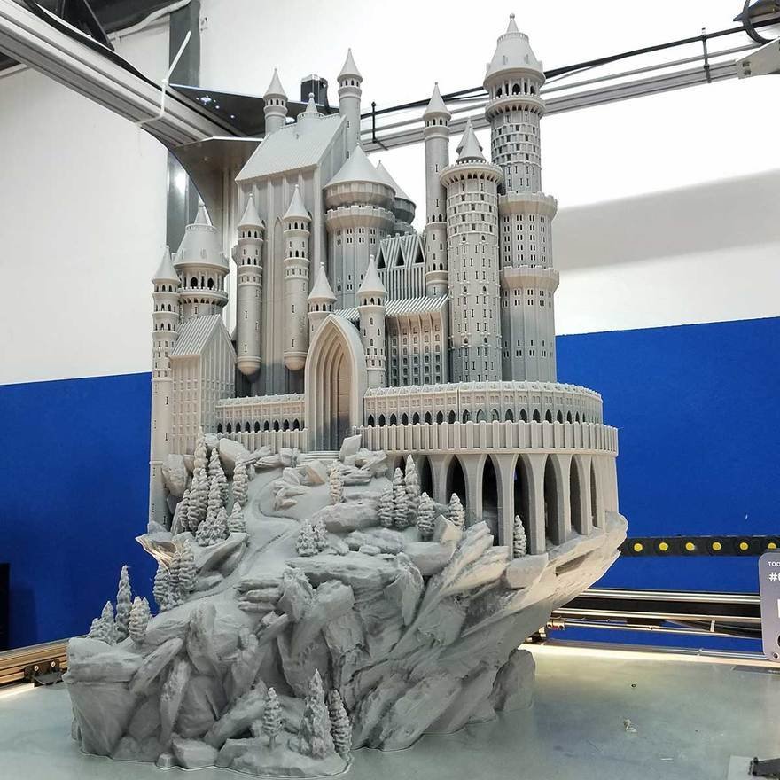
Regardless of which method you choose, if you have a large number of parts it’s also a good idea to add a unique identifier (letters, numbers) to each part to help you solve the puzzle during assembly.
Use the CAD tool of your preference to split your 3D model and add basic aligners like slots, pins, grooves, recesses, and lips or more complex aligners like dovetails and cuts that follow existing creases in the model.
Adding aligners to a design can help when it comes to assembling parts.
In a perfect world these aligners make it simple to align and assemble your parts, but can lead to issues when they turn out even slightly different from your 3D models and don’t line up perfectly. Consequently, only use aligners if your printer can print dimensionally accurate parts that are unlikely to warp.
Splitting your 3D model along straight lines is less design-intensive than adding aligners. Straight cuts are also more forgiving when prints turn out slightly warped or have generally a higher degree of dimensional variation.
Adding identifiers to each part helps you solve the puzzle during assembly.
On the downside, straight cuts can be time intensive when it comes to assembly, as you have to manually align each part and make sure they remain in the correct position until the adhesive fully bonds them.
By default, the stereolithography (SLA) 3D printing process creates fully dense parts. Depending on your design, this might not be a requirement when 3D printing large objects. In such cases, 3D printing the outer shell or hollowing out your design are great ways to save a considerable amount of material and time. When printing hollow models with an SLA 3D printer, be sure to add venting holes to avoid creating pressure volumes with air and resin.
Sample part
See and feel Formlabs quality firsthand. We’ll ship a free sample part to your office.
Request a Free Sample Part
Hollowing out your model can save substantial time and material, as the printer will only need to print the outer shell.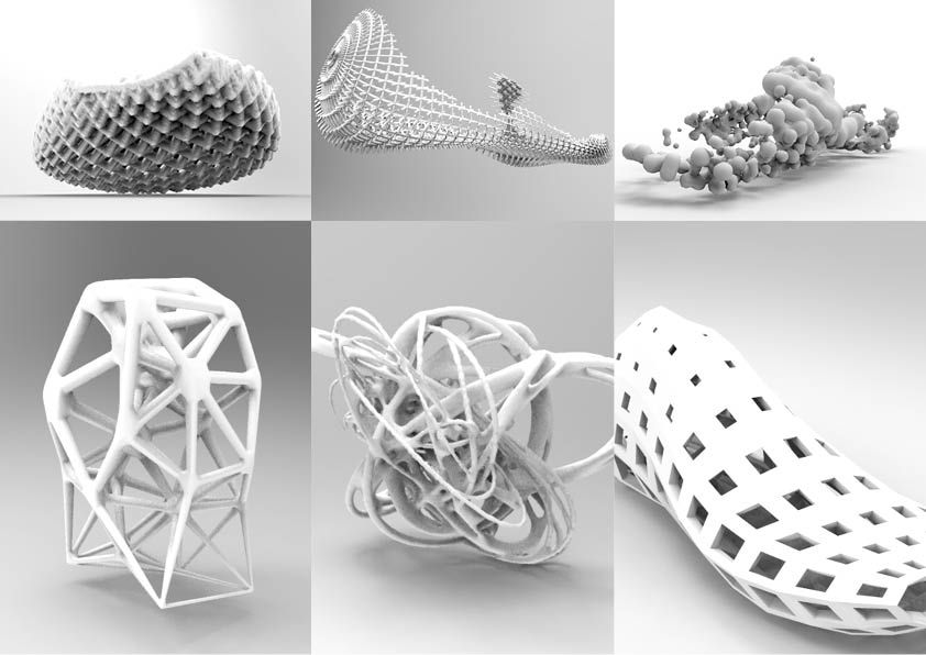
Find out more on how to save material and time by hollowing out your 3D models.
We recommend three methods for bonding parts, depending on their size and ultimate use case:
| Epoxy (5-30 minute) | Cyanoacrylate (CA, Super Glue) | Resin | |
|---|---|---|---|
| Area to bond | Large | Small/Medium | Small |
| Paintable | Yes | Yes | Yes |
| Impact strength | Medium | Low | Low |
For the largest parts and the strongest adhesion, use 5-30 minute epoxy. It has the longest work time, which helps when adjusting the position of larger 3D printed parts, but also leads to an overall slower assembly process. Most 5-minute epoxies won't change shape after about five minutes and reach approximately 75 percent cure strength in less than an hour.
For the largest parts and the strongest adhesion we recommend epoxy.
The next option is cyanoacrylate (CA, or Super Glue), which creates a quick, reasonably strong bond making ideal for small- and medium-sized parts. Clean the part thoroughly before applying it to the surface, as CA does not bond dirty surfaces well. CA has moderate impact strength, but is not recommended for high-impact applications.
For smaller prints you can also simply use the liquid resin from your SLA 3D printer. Pour a small amount of resin into a tray from the bottle or cartridge, use a dropper or syringe to pick it up, and place it onto the surface to bond. Join the parts and wipe off any excess resin that might spill out around the edges. To solidify the resin and bond the parts, use a 5mw UV laser light pen (405nm wavelength) and direct it to the bonding area around the parts.
This method will create a chemical bond, just as if the part was printed on your SLA 3D printer, but is only applicable to small bonding surfaces as the low power light pen cannot penetrate the model deep enough to create a strong bond.
Note: When dealing with resins, make sure to wear protective equipment including appropriate eye protection and gloves.
Webinar
Formlabs 3D Model Manager Evan Fisher walks the viewers through CAD and PreForm tips for larger parts and introduces Form Wash L and Form Cure L for post-processing.
Watch the Webinar Now
Now that you’re finished assembling your model, the final step is post-processing. This step consists of geometric correction of the part to ensure it has an even surface true to your original 3D model and aesthetic finish to get a consistent painted surface.
Depending on the accuracy of your printer and the size of the printed parts, it’s almost inevitable to have slight voids or incorrections where the parts meet. Automotive putty (such as Bondo 907) sticks to the resin well and should be applied to the surface in thin layers to patch these inaccuracies. Alternatively, use resin to fill the seams and cure it using a UV pen. Sand lightly after each layer dries to help bring the part towards its final form.
Patching parts with automotive putty (red area on the image) will help you mend slight voids or incorrections in between parts.
Sanding will help you remove support marks and any remaining inaccuracies from your model. Start with carefully dry sanding the surface using ~150 grit sandpaper to remove large support marks and level the edges where parts meet. Once the part’s surface is even, wet sand it with ~320 grit sandpaper to remove all remaining layer lines. Move the sandpaper in a random motion to avoid creating a grain. In most cases these two steps will create a smooth enough finish, but you might continue increasing the sandpaper grit count by a factor of ~2 and wet sand the entire part until the surface reaches the desired smoothness.
Power sanding works best on large flat surfaces, but can easily destroy small features. For smaller parts we recommend manual sanding, for larger ones a combination of manual and power sanding.
For larger parts, a combination of power and manual sanding can save you considerable time. Power sanding works best on large flat surfaces, but can easily destroy small features, sharp corners, and the subtle contours characteristic of SLA printing. Power sanding also creates a lot of dust, so make sure to prepare the surrounding area.
Note: Power tools require your full attention and wearing protective equipment. It is very easy to leave the sander stationary and quickly wear down that area without realizing it.
Once you’re finished sanding your model, rinse it in soapy water to remove any dust or debris and dry it thoroughly before moving onto the last step.
Priming ensures paint adhesion to the surface and can alert you to where you may need to sand more or trim support marks you may have missed. Generic plastic primer in matte grey shows details exceptionally well—apply it to the surface in several thin coats for the best results. Continue sanding on critical areas, apply a light coat of primer again, and repeat this process until the full part has an even surface.
Note: When priming and painting, wear protective equipment including a respirator designed for paint fumes.
Generic grey primer shows details exceptionally well and will help you uncover spots where additional sanding is required.
Find out more about sanding and priming from our extended guide.
For a finish with multiple colors, you’ll need to mask your model. First, plan the order in which you will paint your model depending on the color, opacity, and size of the area that will have the specific color. Start with the smaller parts so you’ll need to cover less when painting the bulk of the area with the main color. Use painter’s tape for covering the edges and corners, and sheets of paper to cover larger sections faster. Tape guides (lasercut) can also be helpful to create clean lines, circles, and complex shapes.
When it comes to masking, figuring out the correct order is your first priority. In our case, the parts were first painted silver and the sections that would remain silver on the final part were then covered with painter’s tape to hide them from the next l
Just as with priming, apply several thin coats rather than one heavy coat for the best results. Most spray paints work best in warm, slightly humid, and not windy conditions, but always check the specific paint can or technical documentation for the manufacturer’s recommendations.
Consider the time the paint takes to dry: Let layers sit before applying the same color and allow the paint to dry fully before applying a new color.
The area we covered with painter’s tape remained the original silver color after its removal.
Learn the ins and out of painting 3D printed parts in our extensive guide
Wondering how it looks when all these pieces come together?
“Excuse me sir, but that R2-D2 is in prime condition, a real bargain.”
Formlabs Optical Systems Engineer Adrian Tanner 3D printed this R2-D2 replica consisting of 105 3D printed pieces on a Formlabs SLA printer. It even has working electronics inside, borrowed from the Form 2 — the galvo drivers to make the sounds, the cartridge dispenser for lights, and the Z axis driver for the dome motor.
White Paper
In this free report, we look at how in-house large-format 3D printing with the Form 3L stacks up against other methods of production, chiefly outsourcing and using FDM printers. We also compare costs between methods, and review when it would be best to bring the Form 3L in-house.
Download Now
The Form 3L large format 3D printer offers a 30 cm x 33.5 cm x 20 cm build volume for 3D printing massive industrial-quality parts.
Eliminate the turnaround time of outsourcing or the manual work of assembly for large scale 3D prints. Now you can 3D print large objects in one piece with the Form 3L, the first affordable large format 3D printer using SLA technology.
Curious to see how SLA parts perform? Explore our materials to learn more about SLA resins, and request a free sample part to experience SLA quality firsthand.
Request a Free Sample Part
How to 3D Print Large Models Too Big for a 3D Printer – 3D Printerly
Some people want to create 3D prints but they are too big for their specific 3D printer. There are ways to 3D print larger models on smaller 3D prints, so I decided to write an article showing how it’s done.
Keep on reading for the details to get this done properly.
How to Print Large Models on Small 3D Printers
In the absence of large 3D printers, you can still print figures with your 3D printer conveniently. You can take the following steps to conveniently print your large-size figures with your small 3D printer.
Here’s how you can 3D print large models on a small 3D printer:
- Choose a software that can segment models like Fusion 360, Meshmixer, or Cura.
- Import your Model into your Software
- Select the Cutting tool like Plane Cut or Advanced Cuts
- Carefully Segment your Model into Smaller Parts
- Export the STL file or Place it on the Build Plate to 3D print.
- 3D Print the Models
- Bond the parts together using Glue or snap-fit/hinges
- Post Process the parts with sanding and fillers if needed
1.
 Choose a Software
You can make use of quite a variety of software to edit your model. You should make use of the software you are more comfortable with and that is readily available for use. For example, Blender, Fusion360, Meshmixer, Cura, and so on.
2. Import the Model into your Preferred Software
Once you have chosen your preferred software, you would need to import the Model into your software. You can find ready-made models from the web, or you can import the model from your files if you already created one.
3. Select the Cutting Tool
If you choose a 3D modeling software, there are usually two types of cutting tools. You can either make use of Plane cuts or Advanced cuts.
When you utilize Plane cuts, it allows you to split your models across the X,Y, and Z planes of your models. This is the easiest means for you to split your model.
Advanced cuts give you the freedom to cut your models from any point you desire on the model. They are more refined than Plane cuts. It gives you the freedom to select specific points around your model.
This, in turn, helps you mask your cut since you can select specific areas that would hide the cut trace.
Also, advanced cut helps you to maneuver certain features on the model, that would originally be affected if you make use of a plane cut.
4. Carefully Segment the Model into Smaller Parts
Before you begin splitting your model, you would have to consider the implications of cutting the model in certain areas.
For example, you would not want to cut the model where it would be easily noticeable. Also, you would want to ensure that the area you want to cut from, would not be under mechanical stress once it’s bonded together.
Some software has fewer steps than others to split your models. The video below by Frankly Built explains how to fit any model on your 3D printer using Meshmixer.
The steps below show how to make advanced cuts on models using the Netfabb Software:
- Import the STL file for the model
- Select Polygon Cut from the Menu Bar
- Select the next point you want the outline to follow
- Continue adding new points until you get to the end of the shape.
- Then add tolerance to the model and round the corners.
- Separate the models and align them to the base of the virtual container in the software.
You can check out the video below for more information on advanced cuts.
5.
 Export the Segmented Parts as STL files
Once you are done segmenting the original model into smaller pieces, you can now export the models to prepare them for printing.
6. 3D Print the Model
After you have exported the split files into the software, you can now decide if you want to print them individually or together. If there is enough space on the build plate, you can decide to print them together, as this would save more time than printing individually.
7. Bond the Components
Before you begin printing the parts, you need to have decided the type of bonding technique that would suit the model. There are two major methods to bond your components together. They include:
- Glue
- Combine models with snap-fit or hinges
Glue
Glue is a popular adhesive to bond 3D printed components, especially for plane cut models. You can make use of epoxy, resin, or superglue. Epoxy is best suited for bonding models with large surface areas, while Resins and Superglue are for smaller surface areas.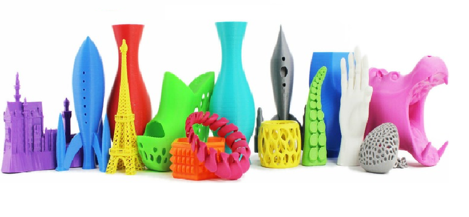
You can get yourself some Gorilla Superglue from Amazon for a competitive price.
Epoxy has a faster bond time than Resins and Superglue. It is also suited for components that would undergo high-impact stress.
Combine Models with Snap-Fit or Hinges
It’s possible to create hinges or a snap-fit design within your 3D prints if you know how to design models. The video below takes you through the steps to do this.
You can also design hinges into your model to bond them together, as well as other joining techniques like laps, grooves, dovetails and more.
Maker’s Muse made a video about this that you can also check out.
8. Post-Process the Parts
After you have bonded the components together, you may want to apply some finishing touches to the completed model. This is to ensure the model has an even surface all around.
At this point, you would need to sand the sharp edges and other misalignment caused when assembling the parts. You can even add filler and sand it to even out any dents or bumps that may be there. A simple Sandpaper Grit Assortment should do be enough.
Bondo All-Purpose Filler from Amazon should work well for this.
How to 3D Print Large Flat Objects & Surfaces
Here are some of the tips to put into consideration when you want to print large flat surfaces.
- Ensure you level the Bed
- Increase the temperature of the heat bed
- Make use of adhesives
- Reduce print speed
- Use rafts and brims
Ensure You Level the Bed
Leveling the bed is important when it comes to 3D printing, especially when you are printing large flat objects. I’d recommend doing some accurate leveling on your 3D printer to make sure your nozzle is extruding on the print bed at a good height all the way around.
A user once had a situation whereby his first few layers were always uneven whenever they print models. He leveled his bed and his print came out fine.
I having this problem, whenever I print large flat surface, the first few layers always very uneven, smaller one seems to okay. How to fix this? Thank you so much. from 3Dprinting
Check out the video below to see how to level your 3D printer’s bed.
Increase the Temperature of the Heat Bed
Having the optimal build plate temperature for larger objects is very important for good bed adhesion.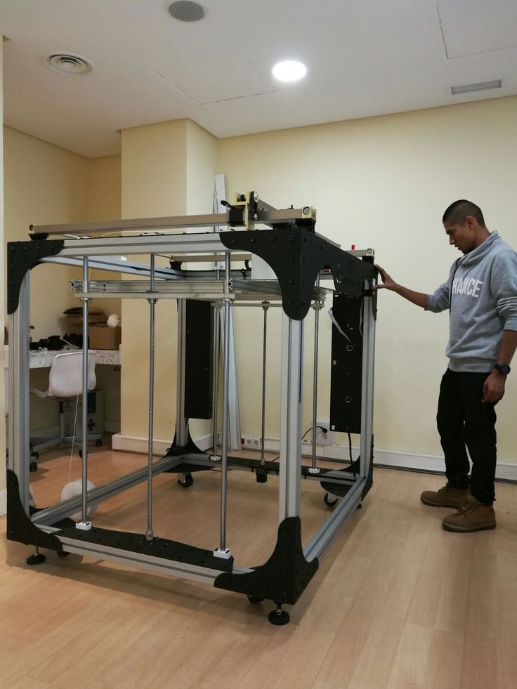 That higher heat keeps your extruded material bonded to the build plate better, allowing it to adhere the whole way through.
If your build plate temperature isn’t optimal, it could lead to warping or worse, a print failure. The optimal bed temperature does depend on the filament you are using, as well as the temperature of the environment you are in.
- For PLA models, the bed temperature usually falls between 40-60°C.
- For ABS models, the bed temperature usually falls between 90-110°C
- For PETG models, the bed temperature usually falls between 70-90°C
Many users have seen better results after optimizing their bed temperature with 3D prints, especially larger ones.
Make Use of Adhesives
Even after leveling and cleaning the bed surface, the filament roll you have might not adhere to the bed adequately in some cases.
When your model does not stick to the bed, you can use adhesives to help keep the model in place and prevent warping.
You can utilize a variety of adhesives for 3D printing in this situation, including Elmer’s Glue Sticks, Blue Painter’s Tape, and hair spray. Personally, I use the glue sticks and they work really well for 3D prints and larger models.
Reduce the Print Speed
Most slicers should have a default Initial Print Speed of around 20mm/s, but if yours is higher, you might want to reduce it. The first layer is the most important, so you want it to be accurately for the best adhesion and to reduce the chances of warping.
Reducing your main Print Speed setting can be helpful as well if it’s too high. 50mm/s is usually a good value to start with.
Make Use of Rafts and Brims
You can also make use of brims and rafts to ensure your flat surfaces are printed well. They are very useful for improving bed adhesion and stability for larger 3D prints. For materials that are known to warp like ABS or Nylon, it’s always a good idea to incorporate a brim or raft.
Brims are thin layers added to the border of the model, while rafts are more of a plate added to the base of the model.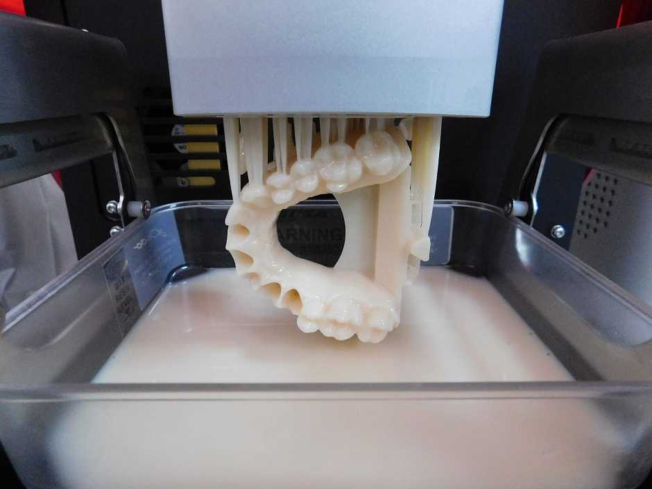 Rafts and brims act as a foundational support that connect the model to the build plate for better adhesion.
You can check out the video below for more information.
How to Resin Print Large Models
Here’s how to successfully 3D print large resin models:
- Orient the model at an angle
- Use Rafts for Better Bed Adhesion
- Use Supports for a stronger foundation
- Increase bottom exposure time
- Make the model hollow
Orient the Model at an Angle
This is the most important aspect of resin printing. When you reorient your model, you significantly reduce its cross-sectional area, especially for flat models.
The standard tilt angle for resin printing is between 30° and 45°. You can also make use of the formula below to calculate the tilt angle for your model.
Tilt angle = arc tan(layer height/pixel width)
The Pixel width is the XY resolution of your model and the layer height is the thickness of each strand of resin deposition.
You can check out this video on why and how resin models are orientated, as well as other tips on resin 3D printing.
When you reorient your large models, it’s a good idea to ensure that the important details of the model are far away from the build plate of the model. This would help hide support marks created after printing.
Use Rafts for Better Bed Adhesion
You can also add rafts to the base of the model for additional support in resin prints.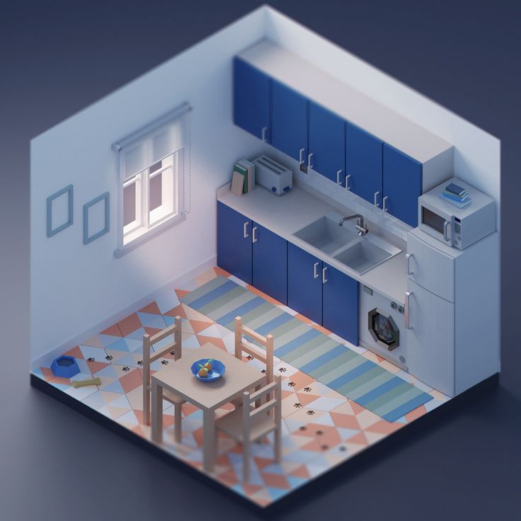 When you add rafts to the model, you can give the model a little clearance from the base for better printing quality.
Make sure your raft actually extends beyond the surface area of the model to improve overall bed adhesion and stability. The default rafts in slicer software usually work well for me, even with larger models.
Make sure your raft isn’t too thick so it’s easier to separate it from the model.
Use Supports for a Stronger Foundation
A key reason why large resin 3D prints fail is because of a lack of supports on the model, especially with heavier parts. It’s important to learn how to support resin models, mainly because you don’t want parts trying to print in midair.
Many slicers are getting better at adding automatic supports, but you also want to manually add supports in places that might have been missed. Each model should be carefully inspected for the best results.
Check out the video below for a useful tutorial to support resin models.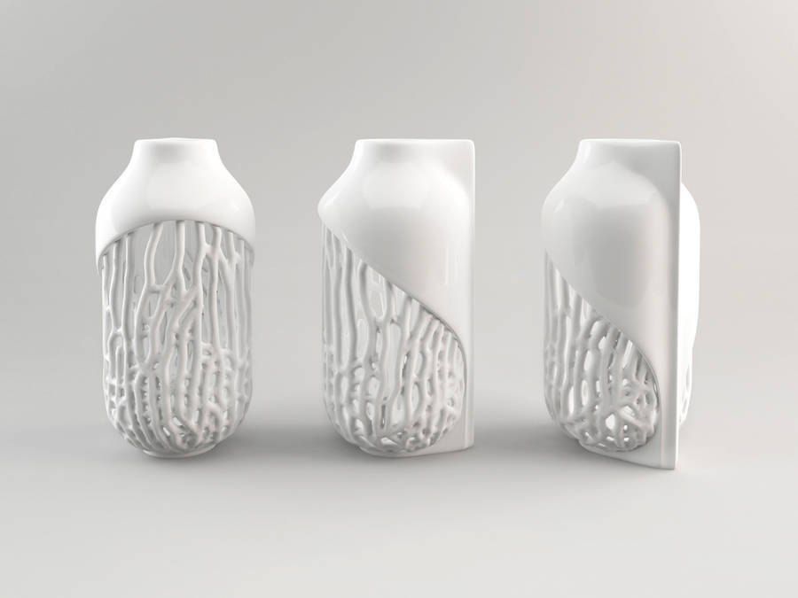
Increase the Bottom Exposure Time
Having strong adhesion is important for larger models, so increasing your Bottom Exposure Time can be a good idea to increase success. I’d recommend increasing your Bottom Exposure Time by around 10-30%.
Doing your own testing is important, so I’d try out some different values to see what works best for you. Try not to raise it too high because models can become hard to remove from the build plate.
Make the Model Hollow
Hollow resin models are much lighter than solid models. Hence, hollow models will exert lower peel force than solid models. Since the main problem with resin printing is adhesion, hollow models help to counteract this.
Also, the resin is quite expensive, hollowing your model will help save resin and also reduce print time. Do keep in mind that if you want a stronger part, you can increase the Wall Thickness of your hollowed model.
Remember to add multiple holes to your hollowed model so the resin can get out of it.
Here’s a video on how to hollow your model on ChiTuBox.
How to create models that are larger than the print volume of a 3D printer
Don't have a large format 3D printer yet? When evaluating the capabilities of a compact desktop 3D printer, do not limit yourself to print volume. Many objects, like your smartphone or a bridge over a river, are made up of many individual components. Therefore, splitting the model into smaller parts that can be aligned after printing is a great solution for 3D printing large objects that do not fit on the platform.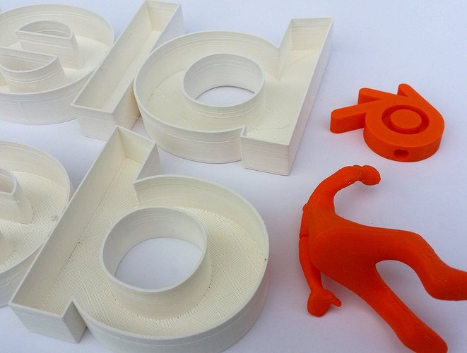 nine0003
Also, splitting the model can be a great way to get a high quality result, even if the whole model fits on the platform. This makes sense when multiple or opposing surfaces must be free from support structures, when the model has complex ledges, or contains cavities where liquid polymer can remain.
3D printing of various parts opens up new possibilities, for example, the creation of prefabricated structures from various materials or the combination of rigid and flexible parts to simulate the overmolding method. nine0003
When choosing a gluing method, it is necessary first of all to take into account the required degree of strength of the glued joints, which depends on the purpose of the models:
-
chemical: use adhesive on artwork, scale models, and complex shapes that are not intended for functional use and should not be impacted;
-
Mechanical: Provide threaded holes or sockets for attaching parts that require a secure mechanical connection, or repeatedly detaching and attaching components as needed.
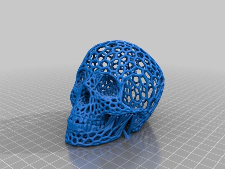 nine0003
This tutorial focuses on building large, prefabricated 3D stereolithographic (SLA) printed models with chemically bonded components. Read on to learn all the steps in this process, from model separation to post-processing for a professional finish.
Formlabs Form 3L is the first affordable, easy-to-use large format 3D printer optimized for reliable production of industrial-quality models. The Form 3L stereolithographic 3D printer features a huge print volume of 30 x 33.5 x 20 cm and unrivaled cost-effectiveness. nine0003
Meet the Form 3L
We recommend two ways to separate models: adding features to the design that will allow the parts to fit together, or separating the model with straight lines, which will require them to fit together properly during the bonding process.
Regardless of which method you choose, if you have a lot of parts, it's helpful to add a unique identifier (letters/numbers) for each one to make assembly easier.
nine0035
Use CAD software to split a 3D model and add basic centering components such as slots, pins, slots, notches, and tabs, or more complex features such as dovetails and slots to match model folds.
Adding centering components to the design makes it easier to assemble parts.
Ideally, these components should make it easier to align and assemble parts, but can cause problems if they differ even slightly from your 3D models, preventing perfect centering. Therefore, it is best to use centering components only when the printer can print parts with accurate dimensions that are not subject to deformation. nine0003
Splitting a 3D model along straight lines requires less effort than adding components to center it. With this separation method, there are also fewer problems if the parts are slightly deformed or differ in size.
Adding IDs for each part makes the assembly process easier.
On the other hand, parts separated by straight lines can be time consuming to assemble, as each part must be manually centered and ensured that they all remain in the correct position until the adhesive is completely dry. nine0003
By default, when printing on a stereolithographic 3D printer, solid models without voids are obtained. Depending on the design, different requirements may apply to the manufacture of large items. In such cases, 3D printing the outer shell or converting the structure into a hollow is a great way to save a lot of material and time. When printing hollow models on a stereolithographic 3D printer, be sure to add ventilation holes to avoid creating cavities filled with air and pressurized resin. nine0003
SAMPLE PART
Experience Formlabs print quality first hand. We will send a free sample of the printed model directly to your office.
Request a free print sample
Converting a model design to a hollow saves a lot of time and material because the printer only needs to print the outer shell.
Learn more about how to save materials and time by hollowing out 3D models.
Depending on the size of the details and the purpose of the model, we recommend three mounting methods:
| Epoxy glue (5-30 min) | cyanoacrylate (CCA, Supercollah) | Resin | ||||
|---|---|---|---|---|---|---|
Square.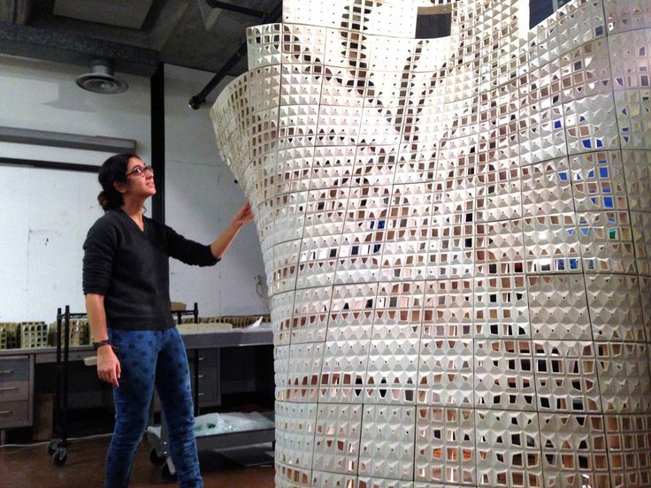 | Large | Small/Medium | Small | |||
| Paintable | Yes | Yes | Yes | 9006 70072Medium | Low | Low |
For large parts and maximum adhesion, use 5-30 minute dry epoxy. It takes longer to dry than other adhesives, allowing you to fit large 3D printed parts but slows down the assembly process. Most 5-minute epoxy adhesives stop changing shape in as little as five minutes and cure by about 75% in less than an hour.
For large parts and maximum adhesion we recommend using epoxy adhesive. nine0003
The next option is cyanoacrylate (CA or superglue), which quickly forms a strong bond, ideal for small to medium sized parts. Thoroughly clean the part before applying CA to the surface, because contaminants adversely affect the quality of the connection. CA has a moderate impact strength, but is not recommended for models that require high strength.
For small models, you can simply use liquid resin from a stereolithographic 3D printer. Pour a small amount of resin into a tray from a bottle or cartridge, pick it up with a pipette or syringe, and place it on the surface to be bonded. Connect the parts and wipe off excess resin that may spill around the edges. Aim a 5mW (405µm wavelength) UV laser pointer at the contact area to cure the resin and bond the parts. nine0003
This method produces a chemical bond similar to 3D stereolithography printing, but is only suitable for bonding small surfaces as a low power light pointer cannot penetrate the model deep enough to create a strong bond.
Note. Protective equipment must be worn when working with polymers, including proper eye protection and gloves.
Download PDF
Don't have time to read the article now? Download it in PDF format.
Download as PDF
After assembling the model, it's time to move on to post-processing. This step includes geometric correction of the model to provide a smooth surface that matches the original 3D model, and aesthetic finishing to obtain a uniformly colored surface.
Depending on the precision of the printer and the size of the printed parts, there will almost always be slight voids or mismatches at the contact points. Automotive sealant (e.g. Bondo 907) adheres well to polymers, therefore, to eliminate such inconsistencies, it is recommended to apply it in a thin layer on the surface. Lightly sand the surface after each coat has dried to bring the model to its final shape.
Sealing models with automotive sealant (red area in image) will help eliminate small gaps and inconsistencies between parts.
Sanding helps remove traces of support structures and remaining inconsistencies in the model. Gently start sanding the surface with 150-grit sandpaper to remove traces of support structures and smooth edges where parts meet. Once the surface is smooth, sand it wet using 320 grit sandpaper to remove any remaining layer lines. Sand the surface in random motions so as not to leave marks. In most cases, these two methods will produce a fairly smooth surface, but you can continue to increase the grit of the sandpaper up to 2 times and, after wetting it, sand the entire model until the surface is reasonably smooth. nine0003
Power sanding is great for large flat surfaces, but can ruin fine details. Grinding of small models is recommended to be done by hand, and for large ones, a combination of manual and mechanical grinding is recommended.
Machining large parts with mechanical and manual grinding saves a lot of time. Power sanding is great for large, flat surfaces, but can ruin the fine details, sharp corners, and subtle contours that are typical of stereolithography. As a result of mechanical grinding, a lot of dust is also generated, so before starting processing, it is necessary to prepare the working area. nine0003
Note. The use of power tools requires full attention and the use of protective equipment.
The surface can be damaged very quickly without even realizing it, just by leaving the sander without moving.
When finished sanding the model, rinse it in soapy water to remove dust and debris and dry thoroughly before proceeding to the last step.
The primer helps the paint adhere to the surface and can indicate areas where additional sanding is needed or removal of traces of supports that you may have missed. The Universal Matte Gray Plastic Primer shows these spots exceptionally well. For best results, apply it to the surface in several thin coats. Sand critical areas and reapply a thin coat of primer. Repeat this process until the entire surface of the model is level. nine0003
Note. Use protective equipment during priming and painting, including a respirator to protect against paint fumes.
All-purpose matt gray primer for plastics is exceptionally good at showing fine details and helping to identify areas that need to be sanded down.
Find out more about sanding and priming in our detailed guide.
When painting with multiple colors, protect the model with a temporary coat. First, plan the order in which you will paint the model, depending on the color, transparency, and size of the area of a particular color. Start with small details so that fewer of them can be protected when painting with the main color. Apply painter's tape to the edges and corners. To quickly cover large areas, attach sheets of paper to them. Ribbon guides (laser cut) can also be useful for creating straight lines, circles and complex shapes. nine0003
When it comes to masking, figuring out the correct order is your first priority. In our case, the parts were first painted silver and the sections that would remain silver on the final part were then covered with painter's tape to hide them from the next l
painting. In our case, we first painted the parts silver and put masking tape on the areas that should remain silver in the finished model so that they do not get paint of a different color. nine0003
As with primer, several thin coats of paint should be applied for optimal results rather than one thick coat. Most spray paints will achieve the best color in warm and slightly damp conditions in the absence of wind. In this case, you must always follow the manufacturer's recommendations, which can be given on the paint container or in the technical documentation.
Consider the time the paint needs to dry: Allow layers to settle before applying the same color and allow the paint to dry completely before applying a new color. nine0003
The area where we applied masking tape is still silver.
Become an expert in painting 3D models with our detailed guide
Already wondering what your finished model will look like?
"Sorry sir, that R2-D2 over there is in excellent condition and inexpensive."
Formlabs optics designer Adrien Tanner created this R2-D2 model from 105 parts printed on a Formlabs stereolithographic 3D printer. It even has working electronics borrowed from the Form 2 printer - a galvanometer drive for sound reproduction, a cartridge dispenser for lamps, and a Z-axis drive for dome rotation. nineThe 0003
Form 3L is the first large-format 30 x 33.5 x 20 cm 3D printer for producing massive, industrial-quality models.
Reduce order processing time when outsourcing or manual work when assembling large-scale 3D models. Now you can print large 3D models in their entirety on the Form 3L, the first affordable large format SLA printer.
Want to see how stereolithographic parts work? Explore our resources to learn more about stereolithographic resins, or request a free sample to evaluate print quality for yourself. nine0003
Request a free print sample
quick tips for moving from CAD to printed was withdrawn from publication due to a technical error. Please be understanding. Thank you!
Whether it's just a hobby or a source of income, 3D printing is always based on product design. Those accustomed to traditional technologies will have to rethink the entire approach to product design and manufacture. nine0003
When the project is ready, a number of additional operations are performed: setting the orientation of the model and other parameters that ensure the proper printing process. In addition, it is necessary to take into account the fact that most 3D printers allow you to choose the degree of filling the model with cellular structures. The correct choice of this parameter provides protection of the object from deformation and destruction during the printing process, as well as significant savings in material and reduction in production time.
Finally, the last factor influencing the success or failure of the 3D printing process is the strength of the connection between the model and the table. If the workpiece is separated from the table during printing, then all the work will go down the drain.
Here, we'll walk you through the 3D printing process and give you a few simple tips for using the power of additive manufacturing in the design phase. In addition, we will dwell on the methods of preparing a finished project for printing, and also consider ways to securely fasten the workpiece to the table. nine0202
These guidelines apply primarily to Fused Deposition Printers (FDM) printers, but may apply to other types of printers as well. The process of obtaining a finished part by 3D printing is basically the same regardless of the method used.
Designing an object
Any 3D printing starts with construction. If you are developing a product yourself, then you need to build a 3D model of it in a computer-aided design (CAD) system to turn the designer's idea into reality. In this case, the object can be both very simple and very complex. However, too thin and too small models should be avoided. nine0003
3D-CAD from Siemens from this article for 49900r (90% discount), the promotion is valid until March 20, 2020. Read more>>
Saving the file in a special format for printing
To print an object, its model must be saved in a special file format - for example, STL, which has become the de facto standard in the world of 3D printing. In this format, model surfaces are represented as a grid of triangles. Simple surfaces are broken down into a small number of triangles.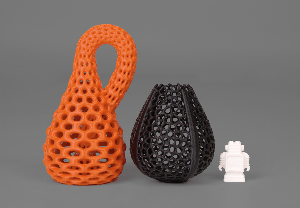 The more complex the surface, the more triangles you will need. Today, other formats are used in 3D printing, in particular, the 3MF format developed by Microsoft. But the most common is still STL. nine0003
CAD-systems make it very easy to save the model in the desired format: just click the Save As command. To improve print quality, it is desirable to set a number of settings for saving to the STL format - for example, the tolerance during transformation and the angle of the plane. The lower the conversion factor and the better the angle, the smoother the printed part will be.
Opening the file in the slicer program
Most, if not all, 3D printers come with their own slicer software. The slicer loads the STL file created in the CAD system and cuts it into layers, and then creates a control program for the printer. nine0003
Positioning the model correctly in the print space
After entering the print settings, the model (or several models) needs to be placed on the printer table.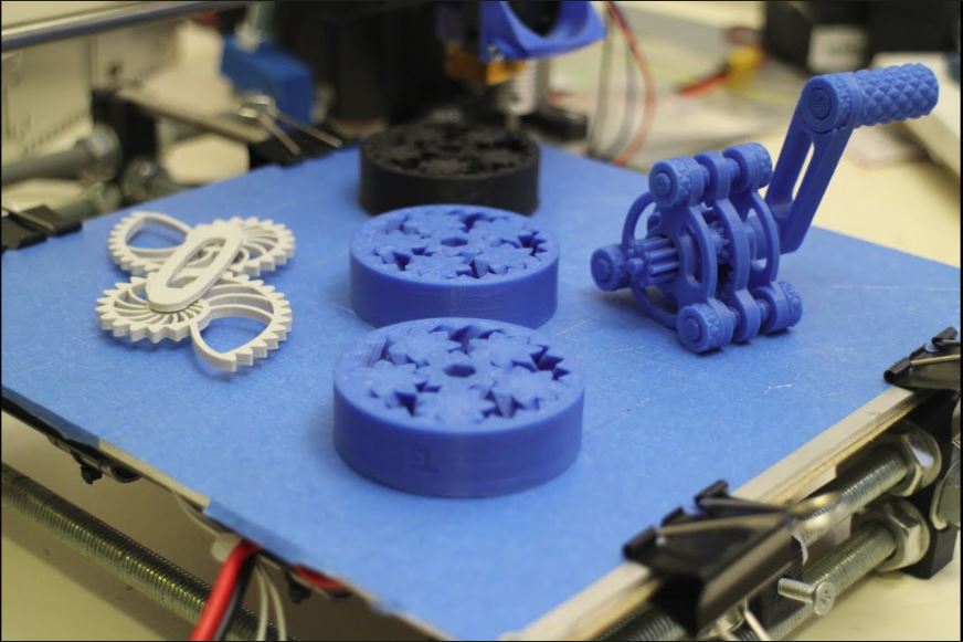 You can print many objects on one table at once. At the same time, compared to printing a single object, the time slightly increases, but in general it still turns out to be less. Here are some tips for choosing the right model orientation.
Set parameters
In the slicer program, the user sets parameters such as print speed, material consumption, nozzle and desktop temperatures. Most slicers have simple settings for beginners. In this case, most often there are also advanced settings so that experienced professionals can achieve optimal results. Advanced settings include percentage infill, amount of backing material, and type of backing or raft (this is a small, thin base that keeps the printed part stable. The backing is removed when it's finished). The number of options is truly endless. Specific settings vary depending on the brand of printer. It's easy enough to set them up. nine0003
Sending the control program to the printer
After setting the print settings, the placement of future objects on the table, their orientation and quality, it's time to finally start the printer.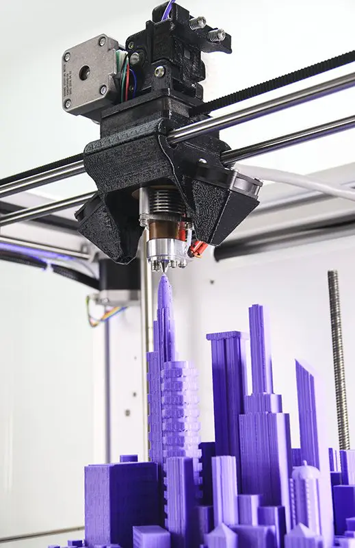 It is enough to press the Print button and find something to do while the production is in progress. Depending on the complexity of the design, the process takes from several minutes to several hours.
Finishing
Finishing includes removing the printed part from the table, as well as removing the support material by melting, mechanical separation or dissolution (depending on the design of the printer). The part may require some light sanding or polishing, but overall a properly printed object looks good from the start. Other types of finishing are placing plastic parts in a container with acetone to smooth out surface roughness, gluing (if the dimensions of the structure exceed the dimensions of the 3D printer or individual elements of the object must have different orientations), drilling holes and painting. nine0003
3D printing process
3D printer design considerations
Eliminate sharp corners
If the direction of the surfaces changes abruptly (for example, a vertical wall intersects with a horizontal overlap), then such a model is difficult to print.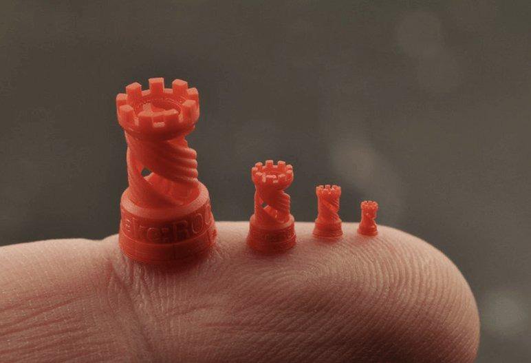 The printer will build excessive inner surfaces, wasting too much material. There are two easy ways to prevent this: add chamfers to smooth out where the surfaces meet, or round the corners so the printer gradually builds a vertical surface. In addition, rounding will increase strength, since destruction most often occurs at sharp corners. nine0003
Elimination of thin walls and small geometries
Layer by layer fusing technology consists in supplying hot plastic through a nozzle with the formation of a printed object layer by layer. The thickness of the extruded plastic layer cannot be made smaller than a certain limit, depending on the diameter of the nozzle and the speed of the print head. Excessively thin-walled details are difficult to print - often the result is a chaotic weave of fibers. If the part can be printed, it is very fragile and breaks easily. nine0003
Too thick walls - also bad
On the other hand, if the walls are too thick, they become brittle and crack easily.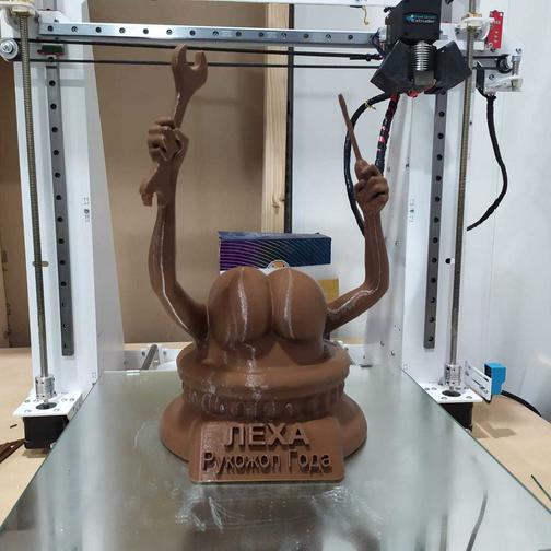 This is especially important when printing from materials other than resins, as excess thickness during the manufacturing process leads to internal stresses in the part. Even when printing from plastics, material is wasted on walls that are too thick and time is wasted.
Removing large overhangs
3D printers allow you to create amazing shapes and surfaces, but they are not capable of printing directly in the air. If there is a void in the part with material above it, additional support material must be used. Most slicers add material automatically, but require you to specify the orientation and volume of the support structure. Printers with a single nozzle create an array of thin columns, which then have to be broken off. The result is an uneven surface. Therefore, it is recommended to avoid large overhanging elements whenever possible in order to reduce the need for support material. nine0003
If such an element is unavoidable, you can try to flip the object. Most printers are capable of printing overhanging elements with an angle of about 45 degrees. At a certain height, the edge of such an element may sag somewhat. The actual capabilities of a particular printer are determined by trial and error.
Holes shrink
Remember that the part is made of heated plastic. As it cools, it inevitably shrinks. Therefore, holes and other critical structural elements have to be made larger so that after shrinkage their size is as close as possible to the required one. nine0003
However, if a tight tolerance hole needs to be made, it is better to print it in a smaller diameter and then ream it with a suitable tool. This is especially true for holes whose axis is parallel to the printer table.
Increasing the footprint
If the area of contact between the object and the base is small, the part may separate from the table during printing. To prevent this from happening, wide bases are added to the model legs, which are installed on the printer table. In general, the closer to the table, the more material must be added to the support. There are other ways to securely fasten the part to the table, which we will discuss a little later. nine0003
Special moves
The right approach to design makes printing easier. In addition, there are special post-processing techniques that are important to be aware of.
Place round surfaces vertically
The model should be oriented so that the minimum amount of support material is used. Ideally, it should rest on the table with a large flat edge. In addition, circular geometry must be placed so that the circular faces are vertical. If we look at the printer table from above, we should see a round silhouette of the object. In this case, the part comes out as symmetrical as possible with the formation of a solid round structure. nine0003
Place voids and holes vertically
If there are voids in the model (for example, it is a rectangular pipe), it is desirable to place such voids vertically in order to reduce the volume of the support material. If you print the pipe in a horizontal position, you will have to provide support for the entire interior. If you put the pipe on the end, then no support is required at all.
The same is true for holes: to get a hole with a straight axis, it is best to print it vertically - in the form of a stack of rings, which avoids warping or deforming a round hole into an oval one. nine0003
Set print quality settings
Proper selection of print parameters, such as STL conversion tolerance and slicer software settings, allows parts to be produced with a surface quality that matches that of cutting. However, this entails an increase in print time. When choosing quality parameters, one should proceed from the purpose of the object: is it a finished product or a prototype? Will the part be visible or hidden? nine0202 The quality parameters also affect the shape of the holes in the part. In CAD files, holes are represented as a set of straight lines at an angle to each other. The higher the quality of the model in the saved STL file, the less the circle looks like a polygon.
Reducing the layer thickness
To obtain the best quality, especially when using layer-by-layer deposition technology, it is necessary to reduce the thickness of the layers. It does increase the print time, but the end result is worth it! nine0003
Optimizing the filling with honeycomb structures
In terms of strength, objects do not have to be solid. Similar to a honeycomb, printers can create a honeycomb infill that balances strength and saves expensive polymer material. However, if the printed part serves as a prototype for strength testing, and the serial product will be manufactured by traditional methods, and also if the part is subjected to certain types of mechanical stresses and pressures, a solid design will be preferable. nine0003
Choosing material
The success of printing largely depends on the correct choice of material.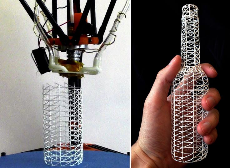 Materials have different properties. For example, the melting point of thermoplastic polyurethane (TPU) and polylactic acid (PLA) is lower than that of acrylonitrile butadiene styrene (ABS). In addition, the material is taken into account when choosing the type of support structures. For an object made of polylactic acid, supporting elements can be made from the same polylactic acid, since it will be quite easy to separate them from the finished part. If the part is printed from ABS plastic, then the support elements must be made from a different material, and it is better not to use such elements at all in thermoplastic polyurethane parts. nine0003
Cellular filling
A solid body is not always the best choice for 3D printing. Printing solid parts has its advantages, but the internal honeycomb structure saves both expensive material and time.
Creating objects with a specified degree of filling with honeycomb structures is a unique opportunity for 3D printing.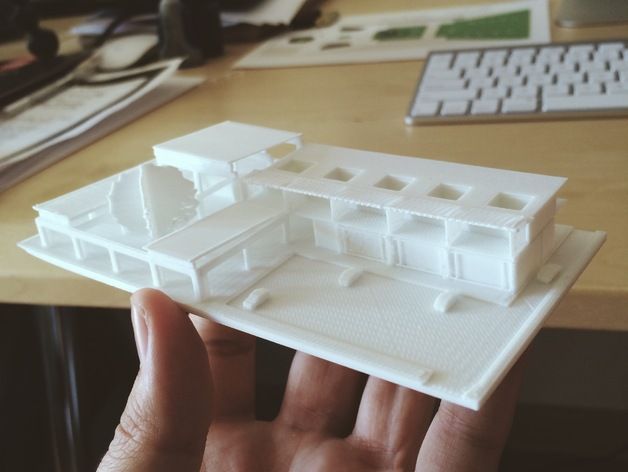 Moreover, it is not required to design such a structure: this is done by the slicer program. As a rule, it is enough to set only the percentage of filling (the closer it is to 100, the more solid the object will turn out) and select the type of cells, if the printer has such an opportunity. nine0003
In addition to saving time and material, the internal honeycomb structure has many other advantages.
Cellular filling prevents warpage
Printing large objects as a single piece introduces a danger of warpage. By reducing the infill percentage, the air during printing passes through the part, providing more uniform cooling and eliminating warpage.
Cellular filling does not lead to loss of strength
Printing cells instead of solid material does not reduce the strength of the part. In many cases, a honeycomb part is strong enough for the chosen application, but lighter and less material intensive.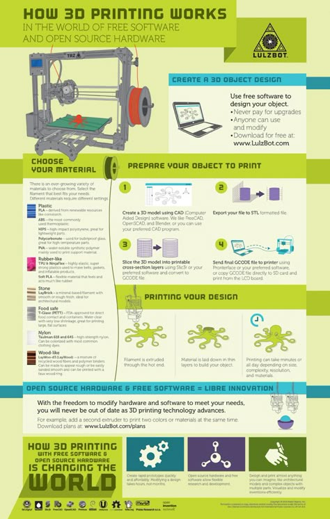 nine0003
The function determines the choice of cell geometry
Most slicers support a wide variety of cell geometries. The optimal option is determined by the functional purpose of the object. Standard box padding simplifies printing, while hexagonal and triangular boxes add strength. Wave fill allows the object to bend or twist.
How do I choose the right filling percentage?
In general, the strength of an object increases as the percentage of infill increases. Most printers have a default infill percentage of 20, which is optimal in some cases but too high or too low in others. Consider mechanical stresses in the printed object and increase the percentage of infill in areas where greater strength is required. If high strength is not required, choose the lowest possible filling. This saves material and speeds up printing. Most often, the selection of the optimal percentage of filling is done by trial and error.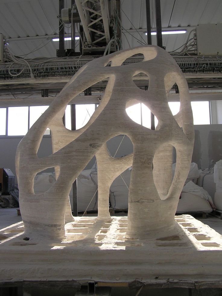 nine0003
Ways of fastening the workpiece to the table
“Rafts”, “brims”, “skirts” – these terms sound funny, but they just refer to the three main ways of attaching a 3D printed part to a printer table. Let's take a look at each of these methods and their areas of application.
Skirt
The skirt involves creating a few rings around the object at the beginning of the print to make sure the plastic is extruded normally. The skirt is not in contact with the object at all. It surrounds the printable area and helps start the fusing process. When creating a skirt, a large volume of hot thermoplastic polymer passes through the nozzle. This prepares the printer for printing the part itself. This guarantees good adhesion to the table and obtaining smooth surfaces of the object. nine0003
Brim
The brim is a wide, flat area connected to the main object as a support base (think of a brim of a hat). It is very similar to a skirt, but connected to the model. In addition to all the advantages of a skirt, the brim keeps the edges of the object being made on the table.
When printing, the outside of an object often cools faster than the middle, causing the edges to curl. Brim prevents this phenomenon by holding the edges.
Raft
A raft is a detachable base, made in the form of a thin mesh platform, located under the entire object (which lies on the raft). To create a raft, the printer first prints a flat plate in two or three layers, and then begins to manufacture the object. nine0003
The rafts provide excellent adhesion to the table surface and also provide a strong print base. This is especially useful when making small and oddly shaped parts that do not fit well on the table, as well as thin-walled objects.
After printing is completed, in most cases the raft will separate easily from the part.
If the printer does not have a heated desktop function
Rafts are used if the printer does not have desktop heating. In this case, excessive adhesion becomes a problem. nine0003
An alternative method is to apply adhesive paper tape to the printer platform, with the edges down if possible (this protects the platform itself). You can also use packing tape, but it is usually more expensive.
If buckling does occur or the object separates from the table, apply a dissolvable glue stick to the adhesive tape. This will enhance adhesion.
Find out the features of a specific 3D printer and take them into account when preparing your model
3D printing is not only a science, but also an art. Effective design for subsequent 3D printing requires an understanding of the technological process, taking into account its features and the purpose of the future object. This will greatly improve print performance. nine0003
Using Solid Edge in 3D printing
Not all CAD systems are suitable for 3D printing
The capabilities of the applied system should not limit the designers. Our Solid Edge system is designed with the latest 3D printing technologies in mind. Various 3D printers and 3D printing services are supported.
Take it to the next level with specific techniques for designing 3D printed parts
Generative modeling in Solid Edge opens up new possibilities: the designer selects a specific material, sets the design space, allowable loads, restrictions and target mass of the part, and the system automatically calculates the desired geometry. As a result, 3D printing methods can produce the most complex shapes.
In addition, when building models, the use of the results of three-dimensional scanning is provided. Solid Edge successfully combines the traditional boundary representation of solid models (B-Rep) and the representation of surfaces in the form of a grid of triangles, which avoids time-consuming transformations that are fraught with errors. nine0003
If you've already downloaded an STL file for printing, our unique synchronous technology allows you to quickly and easily edit your imported models in Solid Edge in preparation for the process.