3D printer popular mechanics
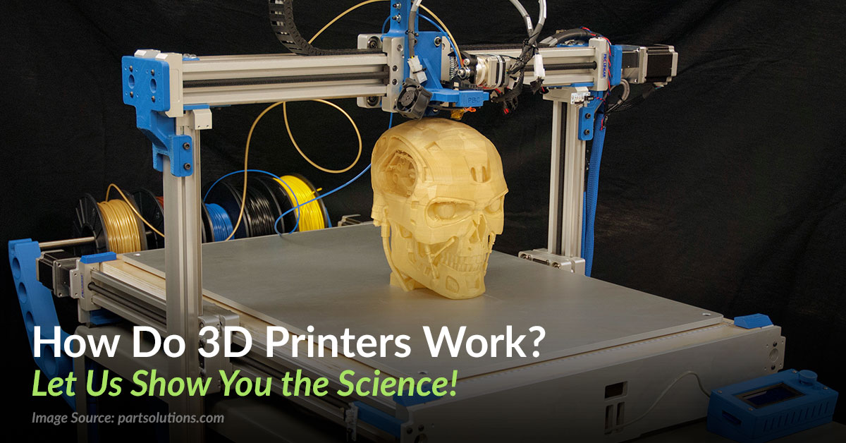
Which 3D Printer Is Best | How Do 3D Printers Work
- Northwestern University researchers have developed HARP, a 3D printer that can print large objects at rapid speeds in a relatively small space.
- The HARP splits the difference between speed and size thanks to a new cooling system, which prevents it from overheating.
- The Northwestern team hopes the HARP will be available for commercial sales in 18 months. No word yet on pricing.
Giant 3D printers could soon be far more accessible. Northwestern University scientists have developed a new 3D printer using a technology called HARP (high-area rapid printing). With a HARP printer, the scientists can print an object the size of a human adult within a few hours.
Northwestern's HARP is 13 feet tall with a 2.5 square-foot print bed. It can print about half a yard in an hour, which the university says in a press statement is "a record throughput for the 3D printing field," and a wide variety of large and small objects at the same time.
"3D printing is conceptually powerful but has been limited practically," says Northwestern's Chad A. Mirkin, who led the product's development, in the statement. "If we could print fast without limitations on materials and size, we could revolutionize manufacturing. HARP is poised to do that."
While HARP is still just being used internally, Mirkin says it will be available for sale commercially within 18 months.
HARP uses a new version of stereolithography (SLA), a type of 3D printing that converts liquid plastic into solid objects. Using an ultraviolet laser pointed at a surface of a liquid thermoset resin, SLA 3D printing first draws an object's support structures, and then the object. Breaking the object into layers, 3D printing company Protolabs says SLA printing has "high accuracy" for details "as small as 0.002 inches."
View full post on Youtube
3D printers generally stay small because the technology can generate a tremendous amount of heat, especially at high speeds.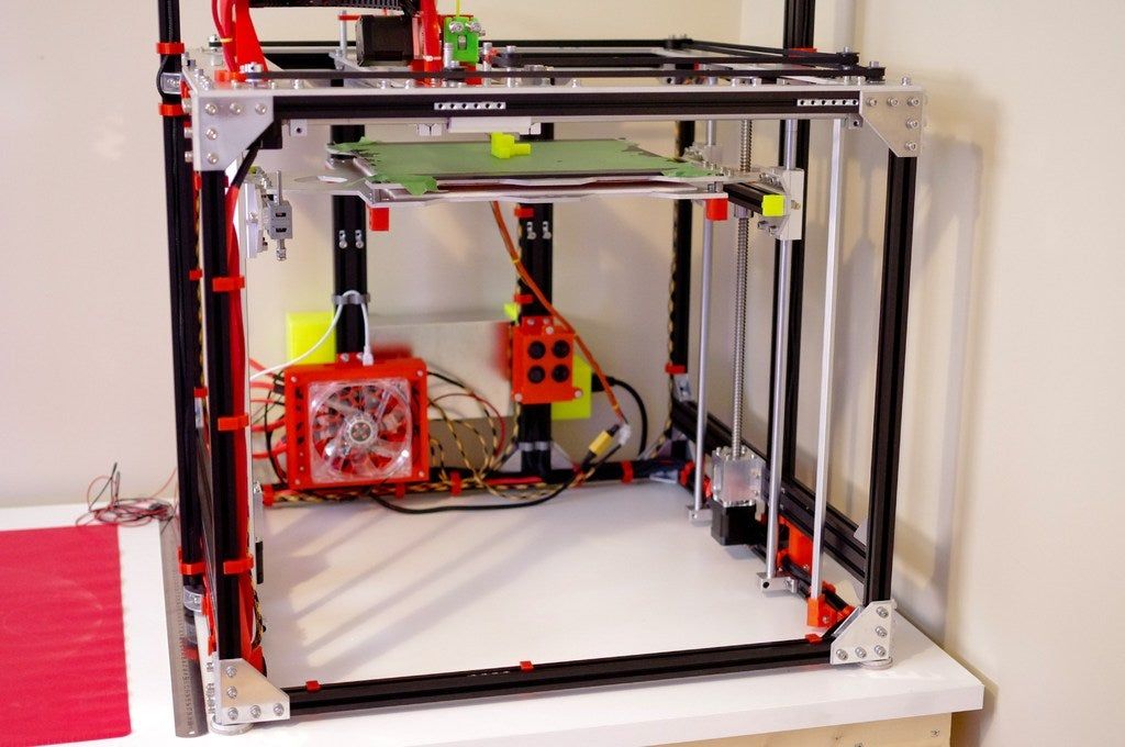 "When these printers run at high speeds, a great deal of heat is generated from the polymerization of the resin," says David Walker, a researcher in Mirkin's lab. "They have no way to dissipate it."
Until now. Using a nonstick liquid that Northwestern says "behaves like liquid Teflon" that flows through the window built into HARP, heat is removed and circulated through a cooling unit.
"Our technology generates heat just like the others," Mirkin says. "But we have an interface that removes the heat."
"The interface is also nonstick, which keeps the resin from adhering to the printer itself," James Hedrick, another researcher in the lab, says in the statement. "This increases the printer's speed by a hundredfold because the parts do not have to be repeatedly cleaved from the bottom of the print-vat."
There are currently ways to 3D print large objects, of course. In 2016, the Guinness Book of World Records awarded the U. S. Department of Energy (DoE) a certification for the largest 3D printed object ever printed, an SUV-sized tool used to make airplane wings. That process took 30 hours, and the DoE described the printer as a "giant" that needed to be stored in a warehouse.
Related Stories
- How To Get Started In 3D Printing
- The Navy Is Putting A.I. Brains Into 3D Printers
- An Very In-Depth Demo of How 3D Printing Works
"When you can print fast and large, it can really change the way we think about manufacturing," Mirkin says. "With HARP, you can build anything you want without molds and without a warehouse full of parts. You can print anything you can imagine on-demand."
"Obviously there are many types of 3D printers out there—you see printers making buildings, bridges and car bodies, and conversely you see printers that can make small parts at very high resolutions," Walker said. "We're excited because this is the largest and highest throughput printer in its class.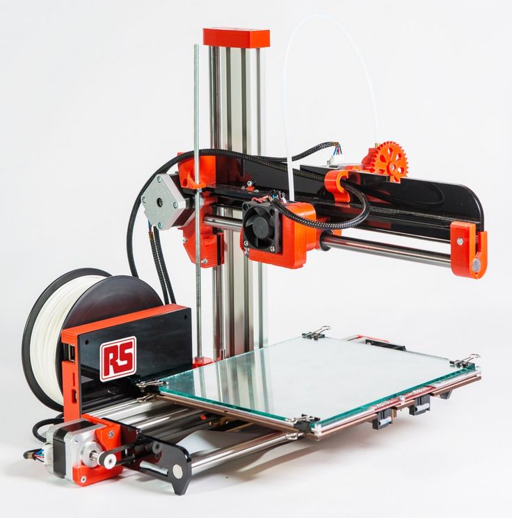 "
"
HARP marks a three-decade journey for Mirkin. In 1999, he built the world's smallest printer. Some of the nonstick technology used in had its earliest iterations within the tiny device. "From a volumetric standpoint, we have spanned over 18 orders of magnitude," Mirkin says.
David Grossman
David Grossman is a staff writer for PopularMechanics.com. He's previously written for The Verge, Rolling Stone, The New Republic and several other publications. He's based out of Brooklyn.
Home 3D Printers | Tiny Home 3D Printer for Cheap
- A tiny 3D printer that began at $59 has earned almost 2,000 preorders on Kickstarter.
- With that price tag, some enthusiasts are skeptical.
- The printer uses renewable PLA plastic, primarily to make small toys and figures.
A project promising a working 3D printer for just $60 (plus $30 shipping) has raised almost $200,000 on Kickstarter.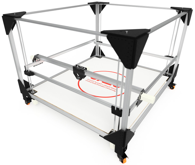 Since the 3DFORT fundraiser went live last month, curious people on Reddit and social media have wondered: How can this thing be legitimate? But even with the skepticism, it’s clear there’s a huge market for a 3D printer that’s truly affordable to a much larger swath of people.
Across all discussions of this printer, commenters tend to say interested folks are better off buying a low-end traditional 3D printer. “Quite a bit more at $300, but well worth the cost,” one Redditor says of the Ender 3, a product at the very bottom end of Creality’s line of printers.
For some groups, 3DFORT is the only affordable option there’s ever been, with a limited use case that scales with the price. Naturally, the printer is really small—the entire roughly cubic unibody is about 9 inches on each side, and the maximum printable size is about 9 centimeters per side.
3DFORT can also only use low-temperature polygalactic acid (PLA) plastic, which is a downside for some kinds of users.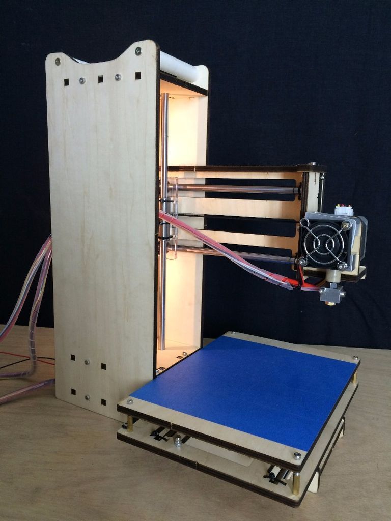 But PLA is made from renewable materials and can be decomposed safely in the right facility.
“The raw material for PLA manufacturing is any fermentable sugar,” manufacturer Cargill Dow (CD) explains in a paper. More from CD:
“Carbon dioxide is fixed in crops to make starches. Agriprocessing like corn wet-milling convert the starches to simple sugars. CD buys the sugar and uses it to ferment lactic acid. Using chemical processing techniques, lactic acid is converted efficiently to lactide, a ring-form dimer of lactic acid. PLA is made through ring-opening melt polymerization. The overall process is sufficiently efficient in terms of yield and energy that the products are economically viable.”
So this small printer uses a renewable kind of plastic to shape very small items, and the Kickstarter page repeatedly references “toy bricks”—a sly genericization of the LEGO brand.
The printer is covered in bumps that users can attach these bricks to. Critics have called this a gimmick, but we suspect it's signaling outright who the makers want this low-cost printer to serve: people with children who want to 3D print small toys and figures.
The printer could make small, sharply detailed shapes in the same vein as the touristy Mold-o-Rama machines—with or without the characteristic burning smell, and definitely without the polyethylene plastic. Nearly 2,000 people have purchased some level of 3DFORT, which kicked off at just $59 plus shipping and is now pre-selling for $79 plus shipping in its final week. We’ll find out soon if the sensibly scaled-down machine does what it promises.
Caroline Delbert
Caroline Delbert is a writer, avid reader, and contributing editor at Pop Mech. She's also an enthusiast of just about everything. Her favorite topics include nuclear energy, cosmology, math of everyday things, and the philosophy of it all.
High speed wide format FDM 3D printer.
Greetings 3d printing enthusiasts and professionals.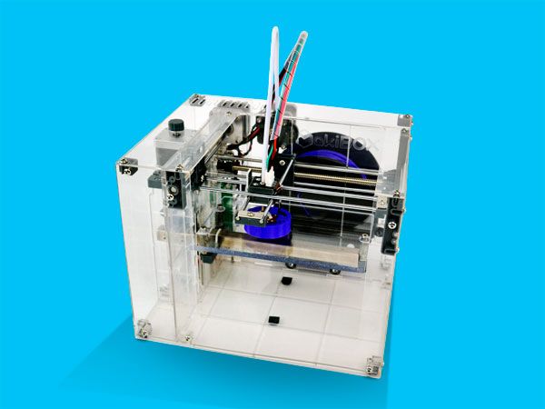 Anyone interested in cutting edge technology.
My name is Alexander Kozlovsky. I would like to share the results of my development. This is the kinematics of movement. Which can be applied in 3D printing, high-precision machine tools and other equipment.
In the article I will talk about the possibilities that this technology opens up in 3d printing. Since this topic is close to 3dtoday.ru readers. And many are interested.
I want to warn you right away, I will not reveal the essence of kinematics in the article. To be able to complete the development before it is copied. It is possible that this kinematics can replace the existing ones.)
And so we went. Buckle up.)
Based on this kinematics it is possible to create printers with high speed and large print area. The performance of the kinematics was confirmed by the production of a prototype.
But before proceeding to the description of the possibilities of this kinematics. And proof of its performance.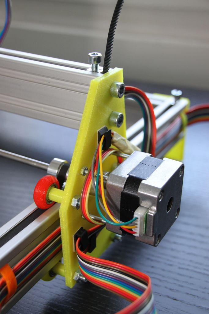 I would like to touch upon the topic of why large-format printing is needed. What difficulties arise when creating such printers. This is important for understanding what qualities a printer should have.
Today, the most common 3d printing technology is FDM printing. A large number of printers have already been developed and are being produced. Based on different kinematics. Also, a wide variety of materials are produced for this technology.
In order not to deviate from the main topic, I will refer to the dagov article about the types of kinematics published on this resource. The article describes in detail the types of kinematics. Thanks dag.
Different types of kinematics have their pros and cons. And depending on the tasks performed and the cost of the printer. Users select the appropriate option for themselves.
The main characteristics by which the printer is evaluated are cost, quality, speed and size of the print area. Unfortunately, there is no universal printer that combines all these qualities on the market yet.
The existing mechanics of the printer does not allow to significantly increase the speed and print area, for objective reasons. The laws of physics apply.) As speed and print size increase, inertia increases when positioning the extruder. Which leads to the need to increase the rigidity of the printer frame, increase the power of the engines. This in turn leads to the need to use high-quality guides, and other related components. Which in turn leads to an increase in the cost of the printer.
Large print area printers cost exponentially. At the same time, even with expensive printers on the market. Relatively slow print speed. It turns out a vicious circle.
I want to note that for printers with a large print area, speed is a key indicator. Since large volumes are printed. Printing time can reach several days, and even weeks.
The speed and print size of modern printers can be judged by what is on the market.
For example, one of the main players in FDM 3d printing is BigRep.
Print speed example. youtube.com
Cost. 3dtool.ru
You can draw your own conclusions about the speed of printing and the cost of printers.
And since there is no worthy offer on the market, not many people can afford large-format 3d printing. This, in turn, hinders the development of related areas.
Large format FDM 3d printer tasks.
I would single out several areas.
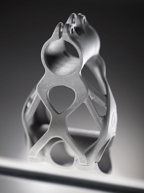
Create large and complex shapes. Hulls of cars, boats, planes, helicopters, drones. Printing for the needs of medicine, prostheses, exoskeletons. Tuning and body kits for cars. Printing molds for casting and composites. Creation of art forms, statues, decorative elements, furniture. And much more.
The possibilities of large-format 3D printing open up great prospects for industrial and domestic applications. And it can accelerate the development of entire industries.
It seems to me that the need for such a tool is very great.
But is it possible to significantly improve the characteristics of modern printers. Reduce cost, increase speed and print sizes. And what are the advantages of the proposed kinematics.
Let's move on to the characteristics.
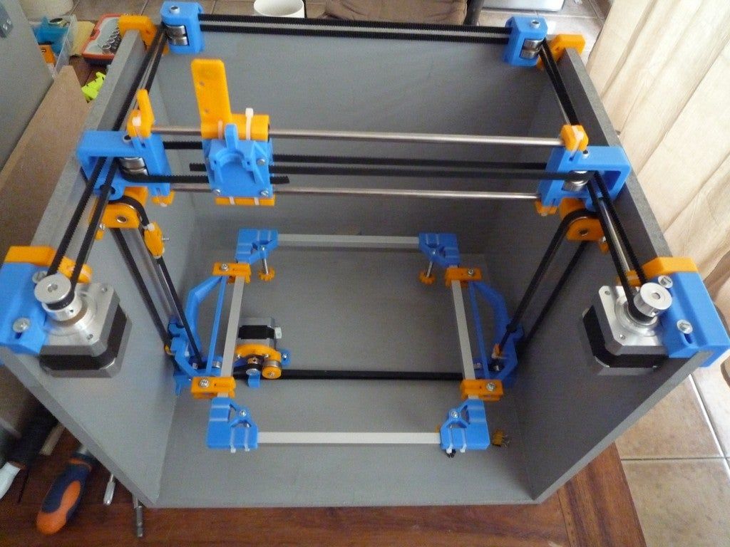
First prototype.
Print sizes up to X400xY700xZ300 mm.
The print speed on this prototype can be increased to 250 mm or more. The potential for overclocking and quality is much higher than that of delta and delta robots. The fastest types of kinematics presented at the moment. But they have two significant drawbacks. Difficult setup (geometric distortion) and relatively small print area. The proposed kinematics does not have these shortcomings.
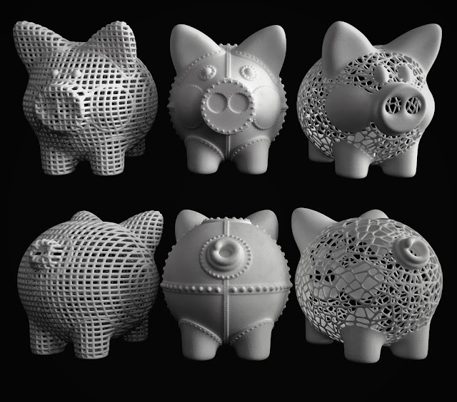
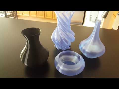
Sample photo from video. Size 60x60 mm.
Second prototype.
Speed test. Dimensions of the print area X550xY900xZ600 mm.
Travel speed over 1000 mm/sec. According to the program 1400 mm/sec.
Planned.
This kinematics allows you to build 3d printers up to 2m per XY axis and more. while maintaining speed. We hope to achieve print speeds of up to 500-1000 mm/sec, even with complex infill strategies. The task is not simple, as many factors affect printing. Which includes the properties of plastic. On the second prototype, an idle speed of more than 1400 mm / s has already been achieved. And this is not the limit.
Also, this kinematics involves the creation of industrial printers with high-temperature chambers for printing with industrial plastics. A high-temperature extruder for these tasks has been developed and is being finalized.
I would like to note one of the important factors. That the overall dimensions of the printer will be slightly larger than the printable area. The printer will be relatively compact. The cost of the printer will be significantly lower than existing analogues. And in terms of characteristics, they are significantly superior.
A prototype printer with a print area of 1x2m (or so) is planned to be built soon. With improved kinematics. The speed of movement will be even higher.
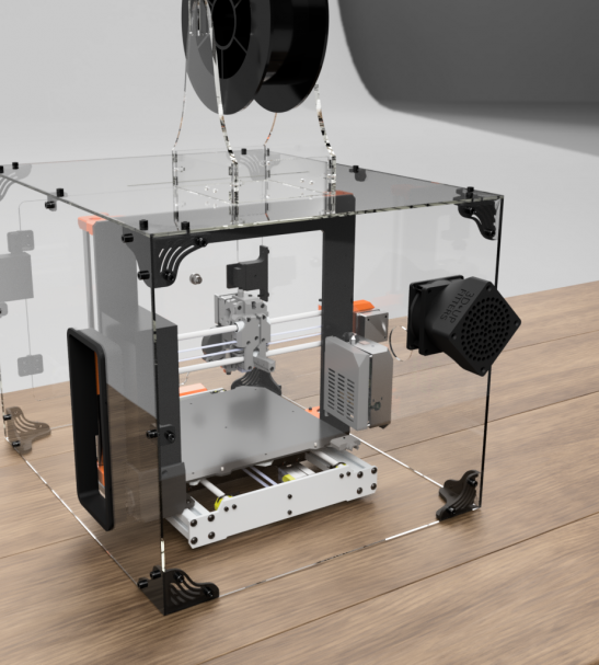
External view of the printer.
Ask questions in the comments. Within the limits of non-disclosure of the essence of kinematics, I will try to answer.
For cooperation email: [email protected]
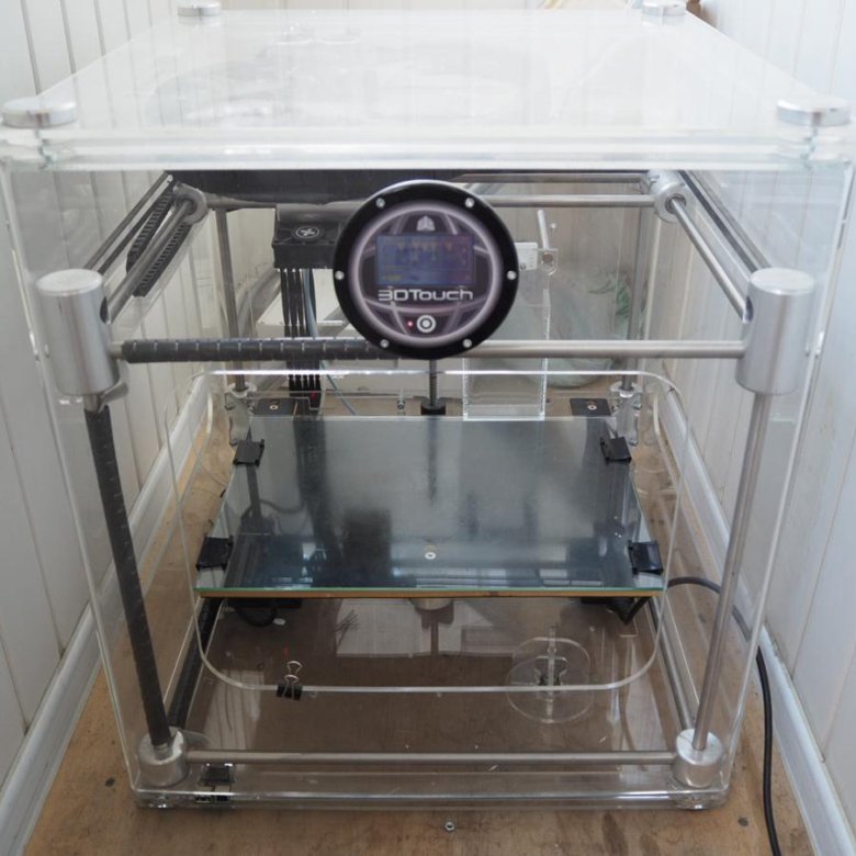
Instructions for setting up all the mechanics of a 3D printer: from belts to speeds
The quality of the printed models directly depends on the mechanics of the printer, namely on its correct settings. Any elements of the printer wear out over time, so the printer must be set up at least once every 5-6 kg of printed filament. With the help of the short instructions described in this guide, you can quickly and easily set up the mechanics of your printer: belt tension, motor current, motor steps, acceleration, jerk and speed.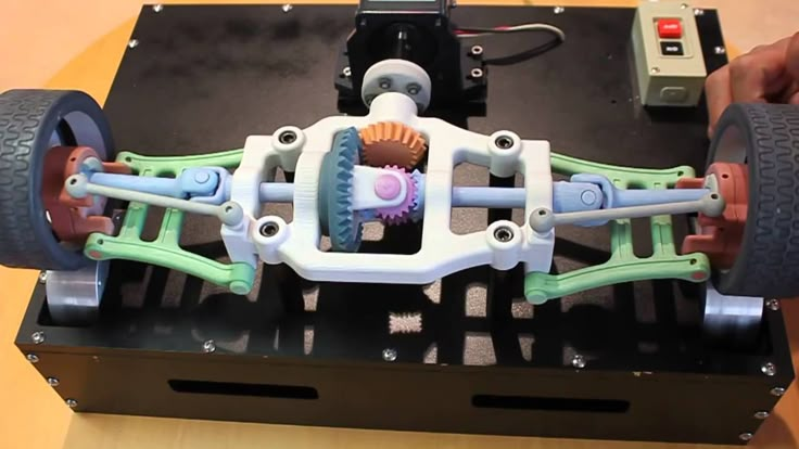
Mechanics includes
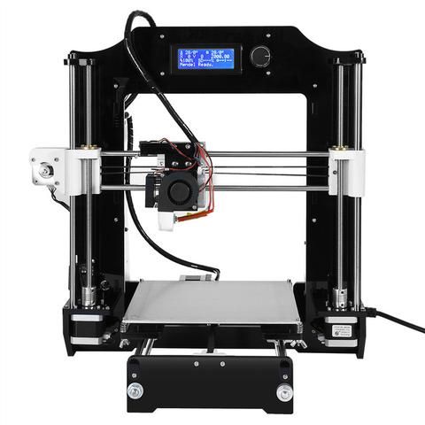
3D printers of any design always contain the same things: Axes and rails along which the elements of the printer move and motors with belts that set these elements in motion. In a classic printer design, there are at least 3 motors (one for each axis), 3 rails (one for each axis) and an electronics board that controls the motors. The latter can hardly be called part of the mechanics, but since it controls the engines, it also indirectly affects the quality of the model.
Printing defects due to mechanical problems
Before changing anything in the printer, you need to decide what exactly needs to be configured. Often defects are visible visually. Our blog has an article about most printing defects, which details the reasons for their occurrence. The following is a list of defects and what element of mechanics they are associated with:
-
Layer shifting - Belts, Motor current, Guides
-
Ringing - Guides, Speed
-
Incorrect model geometry - Guides, Motor steps, belts
As you can see, all the above problems do not interfere with the printing process itself, but the result leaves much to be desired.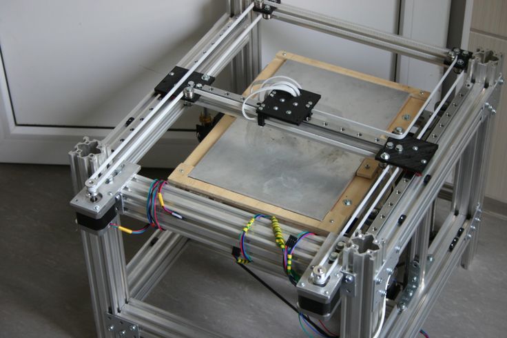 Sometimes mechanical errors can completely stop the printer from working. Therefore, it is better not to take the situation to extremes and, if any problems arise, immediately start checking and configuring the 3D printer.
How to save settings
To fix some defects, you need to change the printer software settings. Therefore, before adjusting the mechanics, it is necessary to understand how to properly store the settings inside the printer. There are 3 ways to do this:
All settings are located in the corresponding menu of the printer
Depending on your firmware, this manual will indicate code sections for MARLIN firmware in the configuration.h file
We first enter the parameters into the printer and then store them in EEPROM - the internal memory of the microcontroller. Or paste all the necessary settings at the beginning of GCODE. To learn how to do this, read our article on working with GCODE and creating macros.
To save to EEPROM, you need to send the printer a command to change some value (which can also be inserted into the initial GCODE), and then send the M500 command (save the current settings to permanent memory).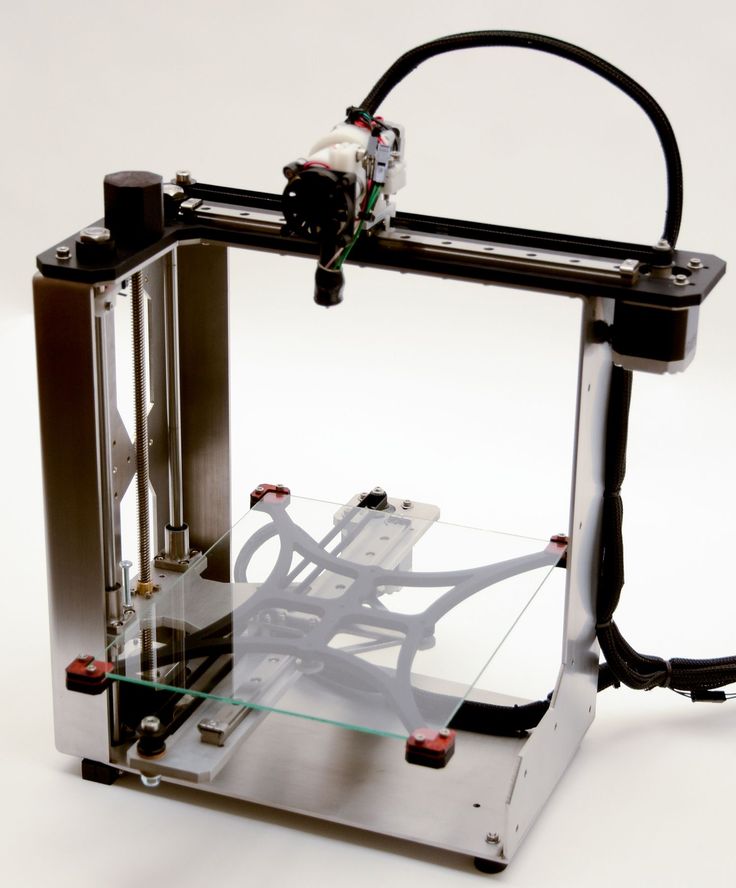 The EEPROM function must be enabled in the firmware, for this you need to remove two slashes in the line:
//#define EEPROM_SETTINGS
Whichever option you choose, you should be careful when using any commands. You will not be able to harm the printer in any way when changing the settings, but if you make a mistake, you will have to look for the cause of possible further problems for a long time.
Setting Instructions
Now you can start setting up the printer itself. If you decide to set several parameters at once, then it is better to use the order of adjustments as in the article, since some of the settings are related to each other and if you use the wrong order, adjusting one element of the mechanics will override the settings of another element. For example, you should not adjust the motor steps before tightening the belts, as changing the length of the belts will change the "true" steps per millimeter of the motors. Also, before setting up, you must make sure that there are no backlashes in the printer frame, tighten all belts.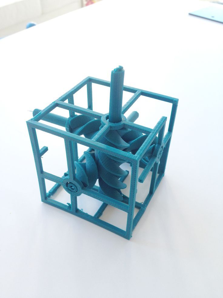
Belts
The first thing to start setting up the printer is the belts. They directly affect the geometry of the model and, when pulled too much, they cause a lot of problems: displacement of layers, changes in geometry, ripples. First you need to make sure the belt is intact. To do this, look at the entire belt, especially the areas where the belts bend. If the belt has outlived its usefulness, then you can see a section of the belt where the distance between the teeth has greatly increased and a metal wire (cord) is visible between them. This means that it's time to completely change the belt.
Broken belt with broken cords
If the belt is intact or you have already replaced it, then you can proceed to the next step. Depending on the design of your printer, you need to move the roller through which the belt passes. The tension should be such that the carriage or table moves effortlessly, but at the same time, when moving quickly, the belt should not slip the teeth on the motor gear.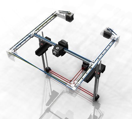 Adjust the tension of the belts on each axis of the printer using this method.
Tip: if your printer came with a belt tensioner in the form of a spring attached to the belt itself, remove it. Due to the flexibility of this tensioner, printing defects will occur, such as protruding corners on the model. It is better to adjust the belt without using this tensioner.
Belt tensioner
Current motors
As we know from the school physics course, the power of the engine depends on the voltage and current strength. Since the voltage on all printer electronics is the same everywhere, the only thing that can be changed is the current on the motor. More precisely, it should be said the maximum current that the driver will supply to the motors. To change this limit, you need to climb inside the case and find the printer board. On it you will see the printer driver. We are interested in a small potentiometer on the driver itself (in the picture below it is indicated as a tuning resistor).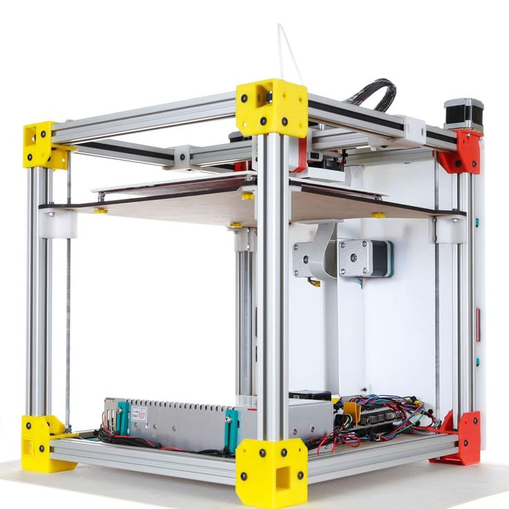
Example of potentiometer location on driver
For adjustment, you will need a voltmeter and a small Phillips or flathead screwdriver. Before proceeding further, it is necessary to calculate the maximum current supplied to the motors. Different formulas are used for different drivers, the most popular ones will be listed in the table below:
| Driver name | Formula | Explanations |
| A4988 | Vref = Imax * 1.25 for R100 | To understand which formula to use, you need to find a resistor with the signature R100 or R050 on the driver. They are located next to the driver chip. |
| DRV8825 | Vref = Imax / 2 | |
| LV8729 | Vref = Imax / 2 | |
| TMC2208 TMC2100 TMC2130 | Vref = Imax * 1. | One formula for all drivers |
 41
41 The value of the maximum current (Imax) depends on the motor controlled by the driver. This can be found in the engine specification or on the sticker on it. The following are the currents for the most popular motor models:
17HS4401 - current 1.7 A
17HS8401 - current 1.8 A
17HS4402 - current 1.3 A
Substituting the value into the formula, we get the Vref value for the maximum current supplied to the motor. But at this value, the engine will get very hot, so the resulting Vref value must be multiplied by 0.7. For example, for a motor with a maximum current of 1.5 A and a TMC 2208 driver:
Vref=1.5*1.41*0.7=1.48V
Now the resulting value can be used when configuring on the printer itself. To do this, disconnect the wires going to the motors, turn on the printer and place one voltmeter probe in the center of the trimmer, and the second probe to the negative terminal on the power supply (you can also use the negative terminal on the printer board and the contact on the driver, labeled as GND). You will see some value on the voltmeter screen. Turn the trimmer clockwise to decrease the Vref value and counterclockwise to increase it.
Attention: you should not specify a Vref value higher than the maximum calculated for your engine! Otherwise, the engine will soon break down!
Once you have adjusted the value on the drivers, you can turn off the power to the printer, connect the motor wires, and put the case back together. This completes the driver setup.
Motor steps
When setting up motor steps, you will need a ruler. For convenience, you can use the program Repetier-Host. The adjustment for each of the three axes occurs according to the same algorithm:
-
Set the caret to zero coordinates (Autohome or G28)
-
Move the carriage some distance
-
We measure how far the carriage has traveled
-
We calculate the correct number of steps per millimeter using the formula:
True steps per millimeter = current steps per millimeter * reported distance / distance traveled
For example, if the printer was set to 100 steps/mm, we tell the printer to move 80mm and the printer travels 87. 5mm. Then the correct steps per millimeter would be 100 * 80 / 87.5 = 91.42 steps/mm. For the convenience of measurements, you can fix a ruler on the table, and a thin object, such as a needle or pin, on the carriage. Then it will be possible to accurately measure the distance traveled. The extruder uses a partially different algorithm to measure distance:
-
Inserting plastic into the extruder
-
Cut it right at the outlet
-
We give the printer a command to stretch the plastic a certain distance (at least 100 millimeters)
-
Cutting plastic again
-
We measure the length of the resulting piece of plastic
-
We use the formula from the previous algorithm
Next, the settings data must be inserted into the firmware in the line:
#define DEFAULT_AXIS_STEPS_PER_UNIT {X,Y,Z,E0}
X,Y,Z and E0 should be replaced by the steps per millimeter for each of the axes, respectively. Otherwise, you need to insert this line into the initial GCODE:
M92 Ennn Xnnn Ynnn Znnn
Instead of nnn in each of the parameters, you must substitute the steps per millimeter for each axis. If you want to adjust the steps only for not all axes, then you can remove unnecessary parameters.
Acceleration
This parameter is responsible for the rate of change of speed. That is, how fast the printer will change its speed. This affects the nature of the movement of the hot end relative to the table. If the acceleration is too small, then the printer will print slowly, if it is too large, then the outer surface of the model will have visual defects: fading waves will be visible near each of the corners, as in the picture below.
To set up acceleration, you need to follow simple steps:
-
Cut a model of a standard test cube with a wall thickness equal to one nozzle diameter, without filling and top layers, bottom 2-3 layers;
-
Open GCODE file in notepad;
-
Find the G28 command at the very beginning and insert the line data after it:
M201 X5000 Y5000
M204 P500 T500
-
Save the changes, print the model according to the received GCODE and note at what parameters P and T it was printed;
-
Open the same GCODE file and change the P and T values on the second line, adding 500 to each;
-
Repeat steps 4-5 at least 3 times;
As a result, you will get several test cubes, some of which will show waves at the corners.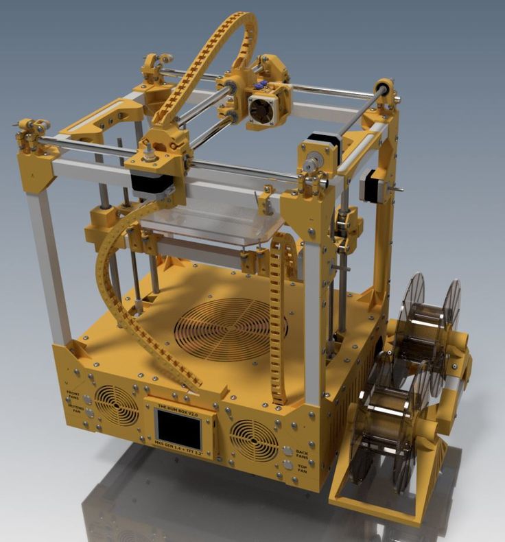 Choose the cube that is printed with the highest P and T parameters, but that no waves can be seen on it. The number in parameter P will be the desired acceleration value. To save this value, you need to find 2 lines in the firmware:
#define DEFAULT_MAX_ACCELERATION {X,Y,Z,E0}
#define DEFAULT_ACCELERATION {nnn}
Instead of X and Y, you should put an acceleration twice as high as found earlier. And instead of nnn, you need to put the acceleration value found earlier. Otherwise, you need to insert a line in the initial GCODE:
M204 Pnnn Tnnn
In the parameters P and T, you need to put the value of the found acceleration. After that, the acceleration setting can be considered complete.
Jerk
A jerk indicates the speed with which to start accelerating. It affects the model in a similar way as acceleration: it creates ripples around the corners of the model. But it also increases the protrusion of the corners if the jerk is too small. The jerk setting is also similar to the acceleration setting:
-
Cut a model of a standard test cube with a wall thickness equal to one nozzle diameter, without filling and top layers, bottom 2-3 layers.
-
Open GCODE file in notepad
-
Find the G28 command at the very beginning and insert the line data after it:
M205 X5 Y5
-
Save the changes, print the model according to the received GCODE and note at what X and Y parameters it was printed
-
Open the same GCODE file and change the X and Y values on the second line, adding 2 to each
-
Repeat steps 4-5 at least 3 times
As a result, you will get several cubes. Find a non-rippled cube printed at the highest X and Y settings. This will be the jerk value for your printer. To save them, you need to find the line in the firmware:
#define DEFAULT_XJERKnnn
#define DEFAULT_YJERKnnn
It is necessary to substitute the jerk values for the X and Y axes, respectively. Otherwise, you need to substitute the command in the starting GCODE:
M205
Instead of nnn, you need to substitute the jerk value found earlier. This completes the jerk setting.
Speed
In fact, there are many different speed parameters, the values \u200b\u200bof which vary greatly. Let's take a look at the main ones:
This parameter is responsible for moving the nozzle without extruding plastic. The value is in the range from 80 to 120 mm/s. Limited only by the maximum speed at which the motors can rotate. Does not affect the model
This speed is important because it indirectly affects the adhesion of the model to the table. Usually lies between 15 and 30 mm/s
-Print speed of inner walls
Usually set to about 60 mm/s, it only affects the strength of the model. Depends on the maximum amount of plastic that the extruder can push through the nozzle
-Speed of printing outer walls
Usually about half the printing speed of the inner walls (30 mm / s).