3D printer lead screw upgrade
Helix Blog | Lead Screws in 3D Printer
With a 3D printer, product developers can quickly and cost effectively create actual physical parts of product designs directly from product design data. Just as a desktop printer produces type on a 2D page, a 3D printer builds a physical object in 3D space, layer by layer.
Rapid Prototyping 3D Multi-Material Printers
For many of today’s manufacturing organizations, 3D printers have become a fixture for the rapid prototyping of parts and products prior to their release for manufacture. With a 3D printer, product developers can quickly and cost effectively create actual physical parts of product designs directly from product design data. Just as a desktop printer produces type on a 2D page, a 3D printer builds a physical object in 3D space, layer by layer. The majority of 3D prints are used for design interrogation and evaluation purposes. Some parts produced on a 3D printer are production-ready. Still others serve as the basis for creating molds for investment castings.
The benefits of using a 3D printer to rapid prototype parts versus the historical practice of machining prototypes as preview parts is that it’s faster and less expensive. However, not all 3D printers are created equal. This article will examine the advantages of using precision engineered lead screws for driving linear motion control applications in 3D printing systems.
Lead Screws Outperform Belt Drives in 3D Printers
Many of the 3D printers on the market today utilize belt-drive technology, which results in inferior performance characteristics when compared to precision-engineered screws. With belt-drive technology, accuracy and repeatability can be issues because belt-drives simply have more play in them, delivering less-precise linear motion control than precision formed or
thread-rolled screws.
Because of the imprecision associated with belt-drive technology, 3D printers that use belt-drives for linear motion control output parts of less than optimal quality, with undesirable surface patterns, and with less resolution on certain types of part features, such as holes and cavities. Screws, on the other hand, provide higher levels of accuracy, repeatability, and performance when used in 3D printers. Thus, 3D printers that operate with lead screws output more precise, better quality parts.
A Screw's Function in a 3D Printer
Within a 3D printing application, screws are typically driven by a stepper motor and guided by profile rails on the X and Y axes. Precision engineered acme nuts are connected to the carriage mechanism. All axes are actuated with a stepper motor- driven screw with an anti-backlash nut, and move along linear ball bearing guides.
An important advantage of the screw-rail configuration for controlling linear motion in 3D printers is that it requires a fraction of the number of components that are necessary for belt-driven 3D printers and takes much less time to assemble.
Compared to belt-drives, which deliver linear motion with repeatability of ±0.1 mm/m and a layer height of 100 microns in 3D printing applications, screws offer linear motion with repeatability of ±0. 02 mm/m and a layer height of 50 microns, making them a lot more precise and accurate for controlling 3D printer performance.
Precision-grade screws have increasingly become the preferred option for low-cost, desktop 3D printers because they deliver the accuracy, repeatability, and performance that users demand - all at at an affordable price. In other words, 3D printer designers no longer need opt for belt drives for controlling linear motion in 3D printers just to keep the cost down. With precision-engineered screws, you can produce high-resolution parts while reducing cost.
Use Helix to Build Top-Performing, Cost-Effective 3D Printers
Contact Helix Linear Technologies to learn how you can use precision-engineered lead and acme screws to develop cost-effective, high-performance 3D printers and rapid prototyping systems. Helix offers a wide array of highly configurable lead and acme screw assemblies that can provide the accuracy, repeatability, and performance that you need to outperform other 3D printing systems on the market.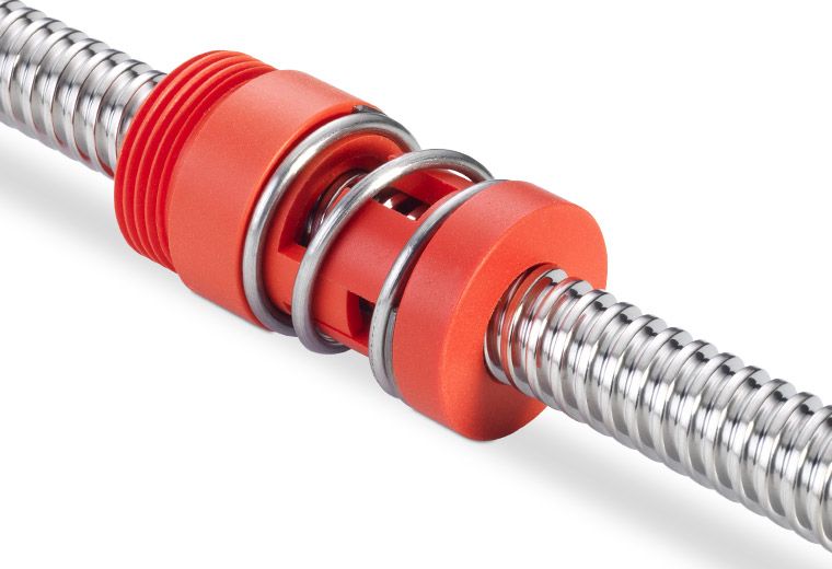
Download our "How Are Lead Screws Used in a 3D Printer?" Case Study
This 4 page case study includes more information about how screws control the precision needed for 3D printers.
Products
Lead Screws
Acme Screws
Lead Screw Nuts
Additional Reading
Are Lead Screws for You?
Lead Screw Actuators Enable World Class Rail Car Design
Additive Manufacturing
3D Printer Lead Screw Upgrade – Harari Projects
danielharari 3D Printed Lead Screw Upgrade, 3D printing 37 comments
I built my 3D printer more than a year ago and I think it’s time for an upgrade.
This upgrade was long due and delayed because of lack of time (I worked full time in the summer) and the crawling pace in which the local postage service here works, but enough excuses – let the fun begin!
before
after
This upgrade will concentrate on the Z axis movement only, and the replacement of the threaded rods with proper lead screws..jpg)
Lead Screw? But Why?
After a year of printing, it can clearly be seen that threaded rods are not meant for this kind of application. The rod itself is not straight (which is not that big of a deal because there are straight rods keeping the movement straight), it squeaks pretty loudly during movement and its threads get full of black goo that consists of dust, oil and metal shavings from the friction with the nut.
old bottom bracket
old right X axis carriage
old left X axis carriage. accidentally widened the holed on the wrong side so I had to mount the motor backwards
old right X axis carriage
old left X axis carriage
old left X axis carriage
A threaded rod is meant to be tightened with a nut and not move, the whole principal of its operation is based on friction – a thing we don’t really want in a moving mechanism.
A lead screw is much more rigid, it’s very hard so it doesn’t bend, it has a very smooth surface and its shape is specifically designed for moving inside a nut.
Made from scratch
I searched for a premade model so I wouldn’t have to model everything from scratch, but with all the different variations and sub-models of the Prusa i3, I couldn’t find one that I was sure would fit without further alterations. Eventually, I decided to design them myself and share for everyone with a similar printer to mine.
I had some big plans and special designs for this project, but It would take a lot of time and I couldn’t stand the threaded rods any more, so I decided to take the current design and improve on it. After the printer is functional with the threaded rods installed, I could take my time and experiment.
This project took two days total over the weekend, including modeling, printing and installing.
new left X axis carriage preassembled
new X axis carriage preassembled
inserting the knurl nuts into the plastic by heating with a soldering iron and guiding with a screw on the other side
new right X axis carriage with knurl nuts inserted and bearing
making sure the holes are clean and the right size
new right X axis carriage with nut installed.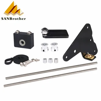
new right X axis carriage with nut installed
new left X axis carriage with nut installed. a recess was made for the top rim of the nut
To keep the nut in place, I embedded M3 knurl nuts in holes in the plastic about 0.5 mm smaller in diameter than the outside of the nuts. The nuts are inserted by heating them with a soldering iron and pushing them in. A screw helps keep the nut straight while it’s inserted.
The linear bearings are held in place by the plastic itself.
all the printed pieces for this project assembled
new bottom brackets and X carriage parts
new bottom brackets. recesses made to accommodate the screw heads
At first, I thought I could get away with replacing only the X axis mounts, but I didn’t account for the lead screw’s center that had to move to make room for the big nut. eventually (after disassembling the printer, swapping the mounts, reassembling and realizing the mistake) I remodeled the mounts, printed them again and reassembled everything.
new top bracket. The bearing was extracted from a flat mounting bearing.
flat mounting bearing donating its organs for science
old top bracket
The old top bracket only supported the straight rod, the threaded rod’s top was floating, which didn’t help with it not being straight.
I improved on the design by including support for the new lead screw, which barely needs it thanks to it’s rigidity.
Instead of letting the lead screw move inside a hole in the plastic, I included bearings that hold the lead screw securely in place while letting it rotate freely.
new bottom mount
old bottom bracket
new bottom brackets. recesses made to accommodate the screw heads
new bottom brackets and X carriage parts
The bottom brackets are basically the same, I just had to move the straight rod’s hole further out to follow the center dictated by the X axis carriage and the bigger lead screw nut.
all the printed pieces for this project assembled
bridging p0rn
All parts were printed in blue PLA @ 0.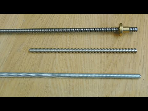 2 mm layer height and 200 degrees C with no support and no heated bed.
All models are available for Free download on Thinginverse.
The lead screw and threaded rod have different thread counts (the amount of turns per length unit) so the steps per millimeter value for the Z axis needs to be changed in the firmware. This is easily done by simply moving the Z axis 100 mm (direction doesn’t matter), measuring the actual movement and multiplying the current steps per millimeter value by the actual movement measured divided by 100 (watch your units). Repeat this process a few times, each time gets you closer until you reach the accuracy wanted.
Note that the error will be more apparent with longer movements. If you move your axis 1 mm and measure you might not see the error. A 1% error would translate to 0.01 mm with a 1 mm movement (which is something my analog caliper can’t measure), but with a 100 mm movement it would be much clearer at 1 mm.
That’s it. All done.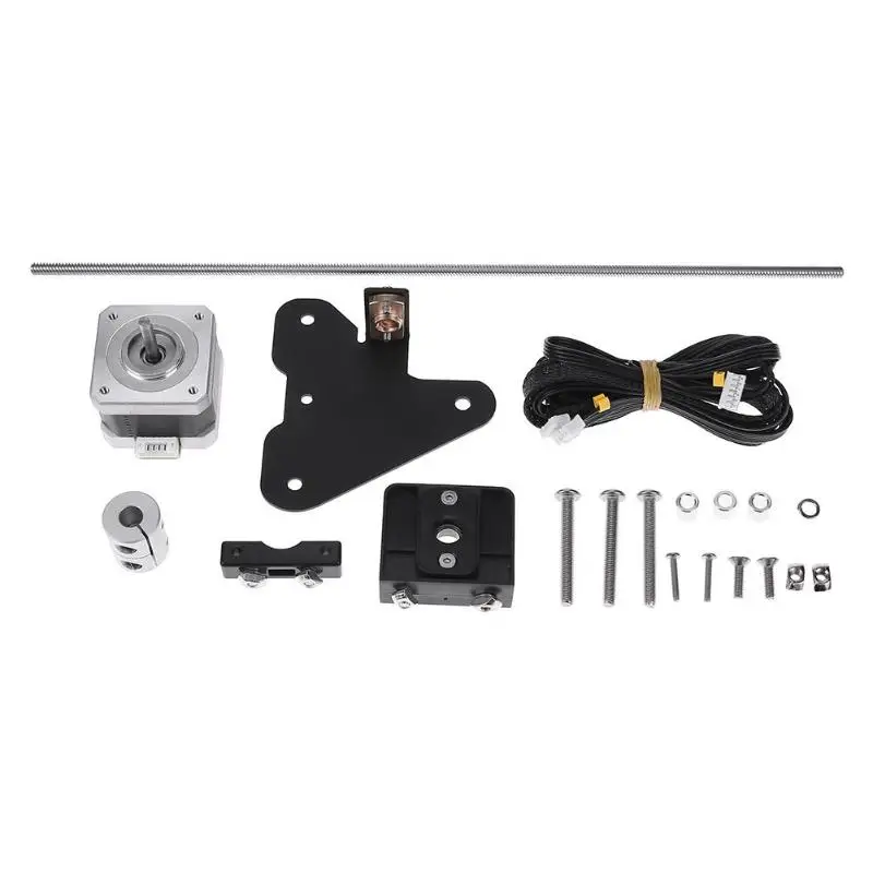 No more squeaking Z axis and wobbly rods. I don’t expect a real improvement in printing quality, although that would be nice, but an improvement in the printing experience.
Final Thoughts
I’ve had some comments about losing resolution with lead screws because of the lower thread count, so lets see if that’s true (spoiler – it’s not):
The threaded rod I had measured at about 1 mm per turn (if I turn it inside a nut once, it will move 1 mm through the nut) and the lead screw measures at around 7.5 mm.
This means that my lead screw is 7.5 times faster than my threaded rod. If I want them to move the same distance, I need to turn the lead screw 7.5 times less than the threaded rod.
If I had a continuously rotating motor, I could, theoretically, have the same resolution (infinite) but the motors used in my printer are stepper motors, these motors move in steps and not continuously. My motors take 200 steps to make a full turn, this is the maximum resolution we can reach (well, there’s microstepping but the idea is the same, there still is a step to be made that determines the maximum resolution and amount of error to be expected).
With 200 steps per turn and 1 mm per turn, we get 200 steps per millimeter. That’s 0.005 mm per step. That’s the smallest increment in length we can make without microstepping.
At 7.5 mm per turn we get 0.0375 mm per step. While this is a larger number, the smallest increment you would expect to make while printing is still even larger. So what does this mean?
This means that the Maximum resolution your axle can reach will go down, but because the actual maximum resolution a 3D printer can reach is even lower, this doesn’t matter.
The maximum resolution I reached with my printer is 0.1 mm layer height and I don’t print at that resolution often. Even if I try to reach 0.05 mm, the lead screw would still be enough. Moreover, my firmware has microstepping enabled so the maximum resolution is much higher (microstepping can go down to 1/32 or even 1/64 of a step) and if I really want to go crazy, I could get geared motors to reduce the ratio to 1:14, 1:30 or even slower.
Like this:
Like Loading.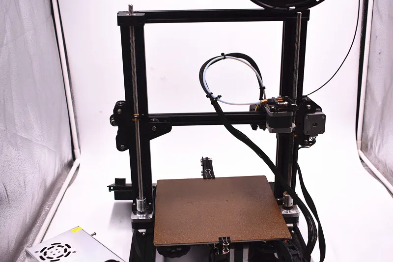 ..
..
Accessories for 3D printers in the category "Engineering and electronics"
PLA plastic for 3D printer 0.800 kg / 230 m / 1.75 mm
In stock in Kiev
Delivery across Ukraine
988 UAH
48002 UAH Buynozzle E3D 0.3mm for 1.75mm thread for 3D printer NB
Delivery in Ukraine
63.02 UAH
81.85 UAH
Shall MK8 MK9 0.2mm thread for 3D printer NB
9 9000Delivery in Ukraine
63.02 UAH
81.85 UAH
Buy
nozzle MK8 MK9 0.3mm under 1.75mm thread for 3D printer NB
Delivery in Ukraine
63.02 UAH
81.85 UAH
9000 9000 2 Dwire stepper motor TMC2130 1.2А for 3D printer nbDelivery across Ukraine
384 UAH
498.70 UAH
Buy
Linear bearing SC8UU for 3D printer, CNC Delivery 90 902b 90 903 across Ukraine0003
162.24 UAH
210.70 UAH
Buy
Warrier E3D 0.3mm under 1.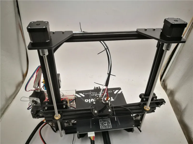 75mm thread for 3D printer Or
68.86 UAH 9000 1.75mm thread for 3D printer Or
Delivery in Ukraine
68.86 UAH
89.43 UAH
Buy
Wide MK8 MK9 0.3mm thread for 3D printer Or
Delivery
9,00068.86 UAH
89.43 UAH
Buy
The TMC2130 step engine driver 1.2A for 3D printer Or
Delivery in Ukraine
9000 389.84 UAH 9000.28 UAH 9000Buy
Delivery across Ukraine
168.08 UAH
218.28 UAH
Buy
PLA (PLA) plastic for 3D printer Black 1.75mm 3kg
0 Delivery across Ukraine
00003
Buy
PLA (PLA) plastic for 3D printer Chorniy 1.75mm 0.75kg
Delivery in Ukraine
365 UAH
Buy
CoPET and PLA plastic for 3D printer 1.7 kg 0.08 kg //
Delivery in Ukraine
300 UAH
Buy
PLA (PLA) Plastic 3DPLAST FILAST for 3D Printer 1.75 mm
In warehouse
Delivery in Ukraine
416 UAH
See also
Teflon FEP film 173x115. 4 mm Anycubic for Photon Mono/Mono 4K/Ultra 3D printers
In stock in Odessa
Delivery across Ukraine
399 UAH
plastic for PLA printer
Buy
Bily 1,75mm 0,75kgDelivery across Ukraine
365 UAH
Buy
100m PLA + Gift! ECO plastic bright for 3D printer pen | 3D plastic thread | A set of plastic 3D pen PLA
In a warehouse in Odessa 9Ol000 ) plastic for 3D printer 1.75mm 0.75kg burgundy
Delivery across Ukraine
365 UAH
Buy
PLA plastic for 3D printer 0.800 kg / 230 m / 1.75 mm
Delivery from KievUAH
489 UAH
Buy
Dikale 3D pen Lapiz 3D Caneta 2nd generation 3D printer for drawing Scribble Pen PLA filament for children and adults
In a warehouse in Ternopil
Delivery in Ukraine 50002n 3D pen0002 Buy
ABS ABS plastic thread 1.75 mm for 3d printers and pens, black
Delivery from Kharkov
425 UAH
Buy
CoPET plastic for 3D9 3. 0 kg / 8005 m Delivery from Kiev
1 170 UAH
1 270 UAH
Buy
Silet for 3D Printer Crealy 0.4 mm for 1.75 mm (Original Nazadka VID Crely)
in warehouse
Delivery
149.99 UAH
Buy
Plastic tube for 3D Printer Crealy PTFE 4 mm - BIL 1m 1.75 mm
In warehouse
Delivery in Ukraine
100 UAH
Buy
Thread Giantm Classic Pla
Ending
Delivery across Ukraine
Specify the price
TEQStone Filament PLA 1.75 mm for 3D printers and 3D pens, roll 1 kg vacuum packed (white)
Ending
Delivery across Ukraine
Specify the price
Each 3D printer - on rails / Sudo Null IT News
I have long wanted to write an article about my positive experience of converting a 3D printer from linear rods to rails, it looks like the time has come.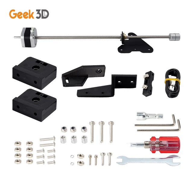
In the course of this article I will tell you what and how I did, perhaps my experience will help someone put their workhorse on the rails.
▍ So let's start.
It seemed that not so long ago there was a dream to purchase a 3D printer, a dream come true, the ANET E16 printer was ordered back in 2019year from Uncle Liao's country.
Surprisingly, the printer arrived quickly enough and the box was almost without dents :) Naturally, the printer was assembled on the same evening and test prints were delivered: cubes, boxes, turrets. Traveled until late at night. The optimal settings were determined, adjusted, the table was leveled. Uhhh, when I remember, I shudder. It took about 2 weeks to set up the printer to achieve an acceptable print quality, but I had to learn to work with this miracle machine on the go, each time solving several tasks at once and not always sequentially. When the experiments led to good results, it pleased, so there is room to grow.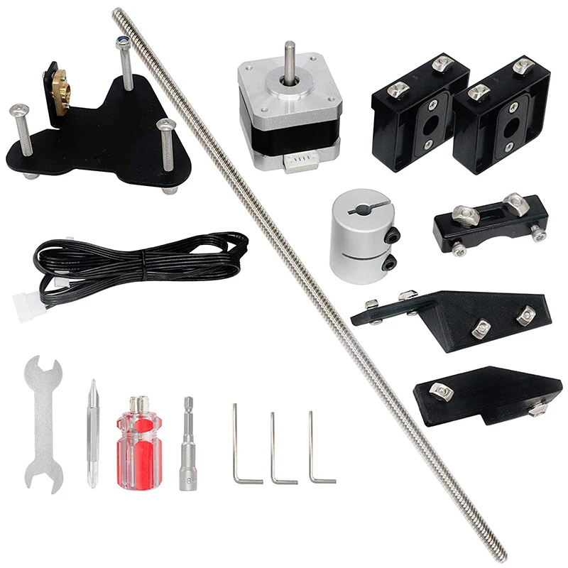
After 2 months of operation, in almost daily printing mode, I began to notice that when the table moved forward and backward (Y axis), as described, steel rods with a diameter of 8 mm (in fact, it turned out to be nickel-plated low-grade steel rods) and linear bearings LM8UU - they creak and the table wobbles, as if riding on potholes. Two rods plus 4 bearings, at first I looked if they were dry - grease was present. It turned out to be a load on the table and, accordingly, on the guide rods and bearings.
Along the guides, paths were gradually drawn from the pulled up material of the rods.
▍ Something needs to be done about this urgently!
Two elements make it difficult to achieve printing accuracy and smoothness of the table:
“Floating table” , you bring the table to “zeros” before the printer starts working, and after starting work, the table leads in an unpredictable way to any of the cardinal directions, because.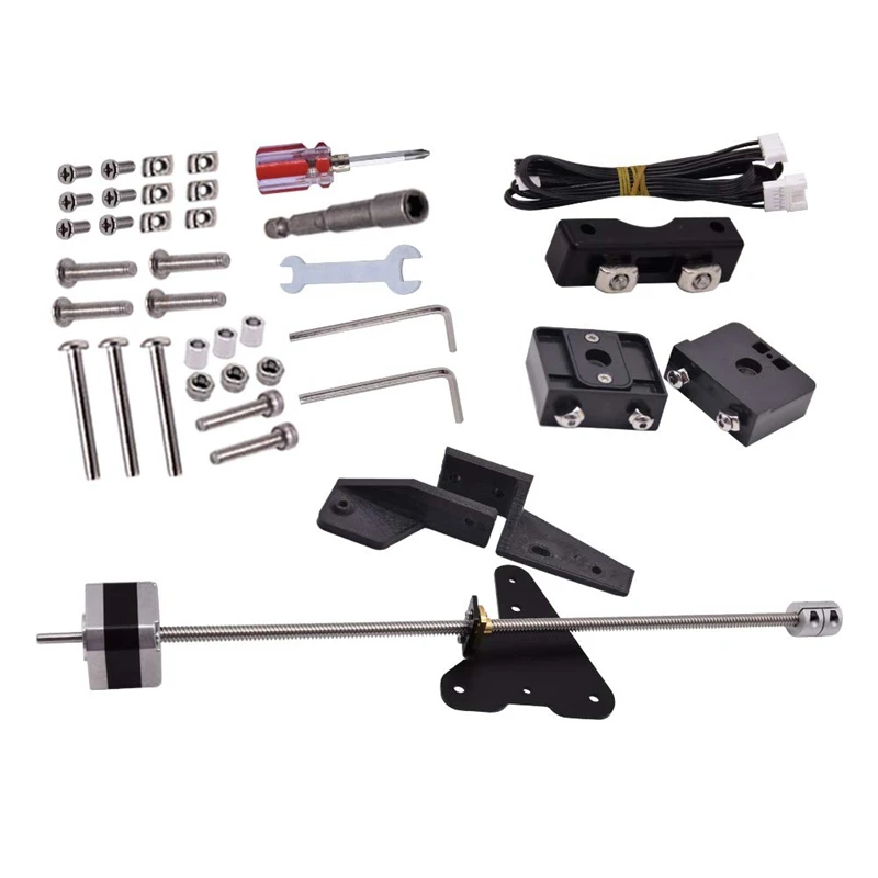 if the bearings work unevenly, then distortions, wedges are provided, a matter of time. 93 = 45,720 grams or approximately 46 kilograms. Even if we take into account that the bearings distribute the load into three unequal parts, roughly 46kg / 3, we get 15 kopecks per third of the length of the rods 50cm / 3 = 16.6 (and 6 in the period) centimeters in the ideal case. Taking into account the fact that the linearity of the rod along the line of movement is a key characteristic and ideally should not change at all, in my case the rods simply bend and this despite the fact that I never gave them the maximum load. Realizing that the rods can’t hold such a weight, he left for a couple of days to read books, google and re-read dozens of forums in order to find out how people live with this and enjoy life by directly moving the 3d printer table?
As shown by the search and the results of reading books and forums, everything was invented before us.
▍ There is a way out! Rails are our everything!
In most options, rails with carriages are preferred, such as these MGN12H. In my case, the carriages were ideal in size and height, because. on the tips of the rails, you still have to install a regular limit microswitch.
The internal arrangement is shown below.
The rails themselves, carriages and bearings are made of durable steel. I ordered in China, from a seller with good reviews. Branded rails and carriages from HiWin cost like a small plane, but they give a guarantee on their rails and carriages.
Let's estimate the "load capacity" of rails and carriages:
- Load capacity stat. 5.88 kN
- Load capacity dyn. 3.72 kN
kN - kiloNewton, kiloNewton Karl !, this is not a mistake, in statics it turns out that a rail with a carriage can withstand a mass in kg: 5.88 * 1000 / 10 \u003d 588 kg will withstand and will not hesitate and will not sell through. I counted twice, suddenly a mistake, I can’t even believe it.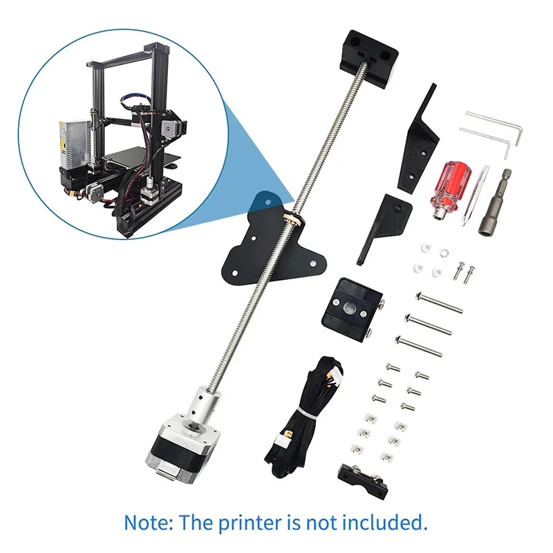 At a rail length of 500 mm, under our table, the rails with carriages do not even move, and before the deflection, the margin of safety is simply huge. I can’t imagine that you can ride on such little girls, just midgets on steroids.
The advantage of rails and carriages is described very simply, they are made with very high precision, the play is so small that when you move the carriage along the rail it seems that it does not roll, but flows along the rail. The move is so smooth that you wonder how so many ball bearings work smoothly. Whoever came up with this design is a genius.
I will have to work with exact dimensions and I will need a working printer to print new parts, I decided to model all the parts first in a 3D editor and not in vain, because fitting in hardware takes much longer than in a 3D editor.
I drew all the important elements: new tips are of a universal type, you can put them in any place, including under the end mic.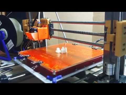
a substrate between the carriage and the table frame - it is very convenient to set up the table after assembling the entire structure.
As a result, after modeling, it turned out to be a fairly reliable, durable and simple design.
I printed for the last time, with a scratch, all the necessary details. He removed the tips, rods with bearings. I installed all the details, connected everything together with screws, that's what happened.
I installed the spring-loaded base of the table in its regular place, inserted the screws into the attachment points of the tips and tightened them according to their native fasteners. This is where the surprise awaited me. The table reached the middle and didn’t want to go further, as if resting on something, the answer came from the manual along the rails ... tolerance for parallelism ...
We are interested in the average accuracy - column H, for a length of 500 mm, Parallelism can deviate by 131 microns, no more. With a micrometer you will not jump, especially in motion.
It was decided to let this dynamic system level itself and self-adjust.
As time has shown, the decision was correct. Having loosened all the screws securing the tips, after 2-3 printing of test tasks, the rails stood up as they should. The carriage with the table rolled to its full length without jamming or stopping. Then the screws were tightened.
I am very pleased with my technical solution. The labor costs and time, not as big as many people think, that I invested in the design of the printer paid off completely, I have been printing since January 2020 and to this day everything works perfectly. And every time, watching how the printer works, I rejoice like an elephant :)
▍ Finally reached the next
- Print quality improved.
- Printing accuracy has become at the level of 0.01-0.03 mm.
- No need to set up and calibrate the table every time, does not lead it, stands dead.
Learn more