3D printer how to make your own
How Do You Make & Create STL Files for 3D Printing – Simple Guide – 3D Printerly
When you are in the field of 3D printing, there are steps you have to follow to be able to actually 3D print your objects. Many steps are done for you but making 3D printer files is one of the most important ones.
This article will show you exactly how 3D printer files are made so read on if you’d like to know.
3D printer files are made by using Computer Aided Model (CAD) software which allows you to create what your model will look like. After your model is complete, you need to ‘slice’ your CAD file in a slicer program, the most popular being Cura. After your model is sliced, it will be ready for 3D printing.
Once you understand the steps of this process and do it for yourself, it all becomes very easy and clear. I will do my best to detail the step-by-step process on how beginners create 3D printer files.
Creating models for 3D printing and learning how to make your own 3D model is a great skill to learn, so let’s get right into it.
- Choose & open a CAD program
- Create a design or model using the tools in your chosen program
- Save & export your completed design to your computer (STL file)
- Choose a slicer program – Cura for beginners
- Open & ‘Slice’ your file with your desired settings into a G-Code File
Choose & Open a CAD Program
There are many CAD programs out there that can be used to create your model, but some are definitely more tiered towards beginners which is what I’ll focus on in this article.
Also, many higher level programs actually need to be purchased, so you’ll be happy to know everything I recommend will be completely free.
The best CAD programs for beginners are:
- TinkerCAD – click and create your own account
- Blender
- Fusion 360
- Sketch Up
- FreeCAD
- Onshape
Check out my article Best Free 3D Printing Software – CAD, Slicers & More.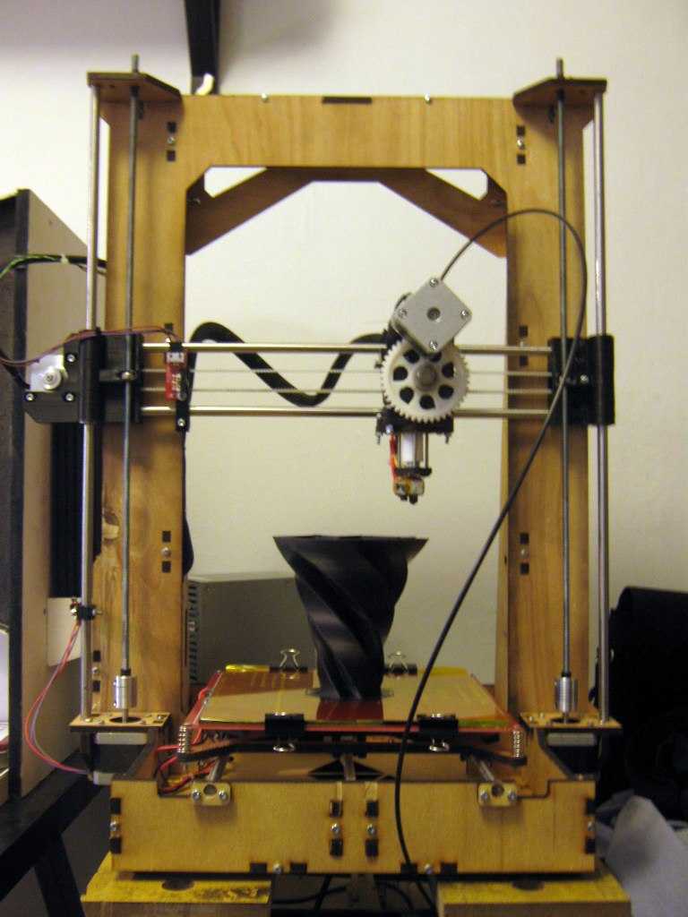
The one that I will focus on and do recommend is TinkerCAD for beginners because it was definitely designed for you guys in mind. Beginners don’t want a complicated CAD program that takes a while getting used to, they want to be able to put something together in the first 5 minutes and see its capabilities.
One of the great features of TinkerCAD is the fact that it’s browser-based so you don’t have to install some huge program file to get started. Just go to TinkerCAD, create an account, go through the short tutorial on the platform and get to modeling.
Once you get the hang of one CAD program and the way designing a model works, you can move onto other programs, but at first just stick to one simple program.
TinkerCAD has enough capabilities to keep you modeling there for at least a few months, before you think about moving to a software with more features. For now, it will work wonders!
Create A Design Using the Tools in Your Chosen Program
TinkerCAD specializes in ease of use, as you put together blocks and shapes to gradually build a more complex structure that you can be proud of.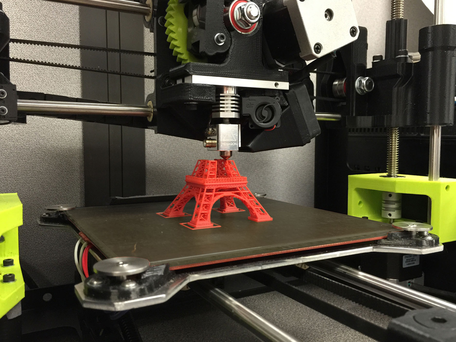 The video below will show you a quick tutorial on exactly how it looks and how it’s done.
It’s always best to follow a video tutorial when learning how to create designs, while doing the same thing in the program yourself.
Reading a guide of some sort is great when you understand the program and are looking for ways to do cool, new things but when just starting out, get the experience behind you.
Once you’ve created some of your own models by following a tutorial, a good point to go to next is to play around in the program and get creative. One thing I chose to do is find a few household objects and try to model it as best as I could.
This ranged from cups, bottles, small boxes, vitamin containers, anything really.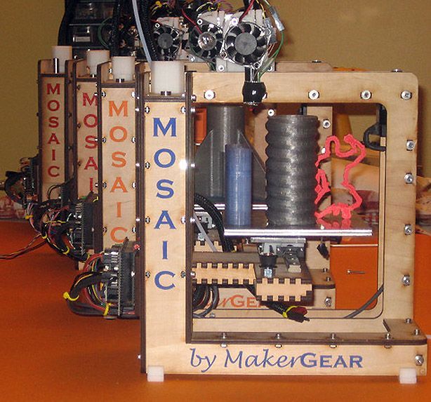 If you want to get really accurate, you can get a sweet pair of Calipers from Amazon.
If you want a quick, cheap but reliable set I’d recommend the Sangabery Digital Caliper.
It has four measuring modes, two unit conversion & zero setting function. You can get very accurate readings with this device, so I do recommend you getting one if you don’t already. Also comes with two spare batteries!
If you want a higher quality Caliper, go for the Rexbeti Stainless Steel Digital Caliper. It is more premium with a polished finish and a case to hold the device. It comes with IP54 water & dust protection, has 0.02mm accuracy and is great for the long-run.
Once you get some good practice creating different items, you’ll be a lot more prepared to start making useful and complex 3D printer files.
At first, it seems like all these simple shapes and holes won’t be able to make much. This is what I thought at first before seeing what people could really create in this software.
The following was made on TinkerCAD by Delta666 found on MyMiniFactory. It would be hard to describe this as a simple design, which just goes to show you the potential you could have with designing your own 3D printer files.
Save & Export Your Completed Design to Your Computer (STL File)
The great thing about TinkerCAD is how it’s made for things to be easy to use. This also includes saving and exporting your STL files straight to your computer.
Unlike some downloaded CAD software, this one auto-saves your work each change you make so you don’t have to worry about losing your work.
As long as you have named your work in the top left, it should continue to save. You’ll see a small message saying ‘All Changes Saved’ so you know if it’s working.
As you can see in the picture, exporting your CAD files into a downloadable STL file is a piece of cake. Simply click the ‘Export’ button in the top right of your TinkerCAD page and a box will pop up with a few options.
When it comes to 3D printing files, the most common ones we see are the .STL files. There are a few things that people say it’s abbreviated from such as Stereolithography, Standard Triangle Language and Standard Tessellation Language. Either way, we just know it works pretty good!
The complex part behind STL files is that they are made up of several tiny triangles, with more detailed parts having more triangles. The reason behind this is 3D printers can better understand this information with this simple geometric shape.
Below is a clear illustration of these triangles making up a model.
Choose a Slicer Program – Cura for Beginners
If you’re in the 3D printing field, you either would have come across Cura by Ultimaker or are already well-versed in the program. Cura is the most popular, cross-platform slicing software that 3D printer hobbyists use to prepare their files for 3D printing.
There isn’t much point trying to go with another slicer because this one works so well and does exactly what you need it to do. It’s very beginner-friendly and doesn’t take long at all to get the hang of it.
There are other slicer programs out there, some even dedicated to specific 3D printers like PrusaSlicer or ChiTuBox. They all essentially do the same thing but Cura is the choice I recommend.
Check out my article Best Slicer for the Ender 3 (Pro/V2/S1), which also goes for other 3D printers as well.
Open & ‘Slice’ Your File With Your Desired Settings Into a G-Code File
The term ‘slice’ your file is one that is widely used in the 3D printing field which means to prepare your CAD model and turn it into a G-code file which 3D printers can make use of.
G-code is basically a series of commands that tell your 3D printer what to do, from movement, to temperatures, to fan speed.
When you slice your file, there is a certain function where you can preview your model in its 3D printing form. This is where you view each layer of your 3D print from the ground, up and you can even see the direction your print head will go while in the printing process.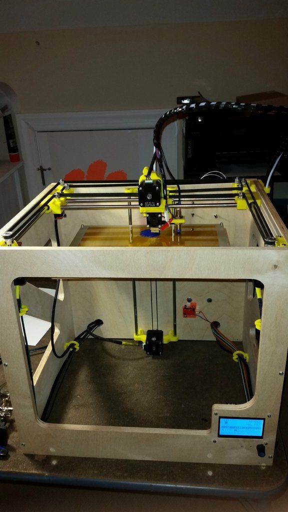
It really isn’t as complicated as it looks. All it really takes is looking over the settings and hitting the blue ‘Slice’ button on the bottom right of the program. The box to the top right shows a simplified way to change settings without getting into all the specific settings.
It’s a spice rack in case you’re wondering!There are many settings in your slicer you can take control of such as:
- Print speed
- Nozzle temperature
- Bed temperature
- Retraction settings
- Print order prioritization
- Cooling fan settings
- Infill percentage
- Infill pattern
Now just because it isn’t complicated to get started doesn’t it mean it can’t get as complicated as you’d like it. I’m sure there are settings that Cura experts have never thought about touching.
This really is a short list when you have seen just how many settings there are, but luckily, you don’t have to worry about most of the settings. Cura has default ‘profiles’ which give you a list of already done for you settings that you can input.
This profile usually works great by itself, but it can take a little tweaking on the nozzle & bed temperature before you get some great prints.
There is a cool menu which allows users to choose custom setting views for beginners to masters, down to custom so the functionality and ease of use is great.
After you follow all these steps, you’ll have created your 3D printer file which your printer can understand. Once I’ve sliced a model, I simply get my USB drive and micro SD card which came with my Ender 3, plug it into my laptop and select the ‘Save to Removable Device’ button and Voilà!
I hope these steps were easy to follow and help you get started making your own 3D printer files.
It’s an amazing skill being able to design your own objects from start to finish, so try your best to stick with it and become an expert in the future.
If you found this helpful, I have other similar posts like the 25 Best 3D Printer Upgrades/Improvements You Can Get Done & 8 Ways How to Speed Up Your 3D Printer Without Losing Quality so feel free to check them out and happy printing!
How to Build a 3D Printer From Scratch
If you are reading this article that means that you’ve probably decided to join the community of 3d printing enthusiasts and find out more about 3d printers, or maybe you have already got some experience in it and are ready to try to create your own 3d printer from scratch.
In this article you will find general understanding how 3D printers can be built as well as links to really useful resources where you can find more detailed information with step-by-step description.
Currently there is a big variety of 3d printers in the Internet that already assembled and are ready to print right after you unpack them from a box, of course you also need to buy a 3d printer filament for it. Do not forget that not all 3d printers can use the same filament types, so please read the instruction before you purchase it.
But for some people who love to make something new with their own hands can be more interesting to build their own 3d printer from scratch. Based on our research the 3D printing community is filled with many enthusiastic people so called DIY’ers (Do It Yourself’ers), who are fascinated with building 3d printers literally almost from scratch.
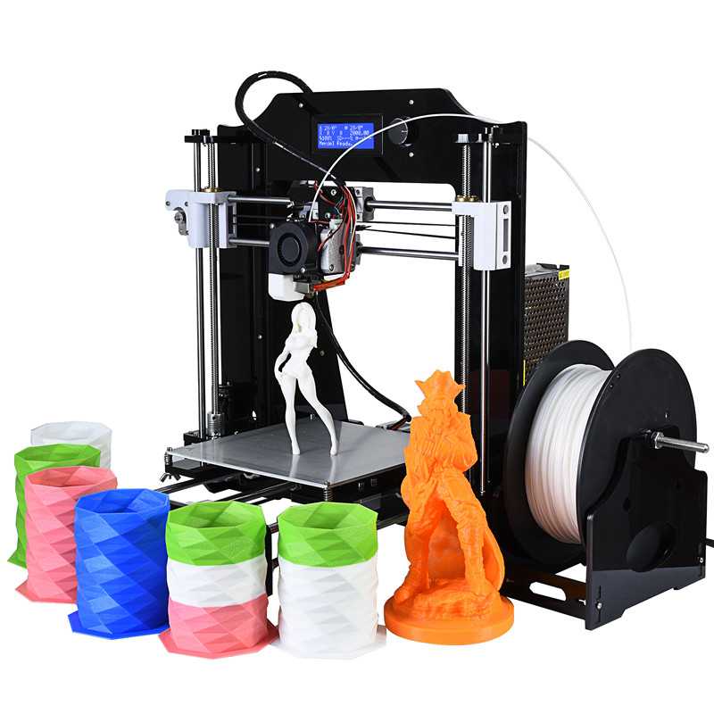
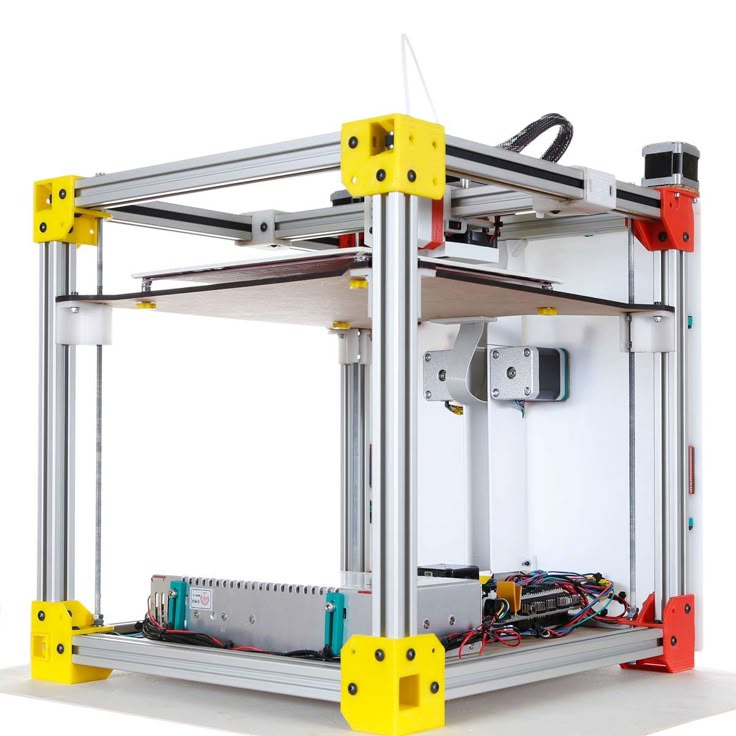
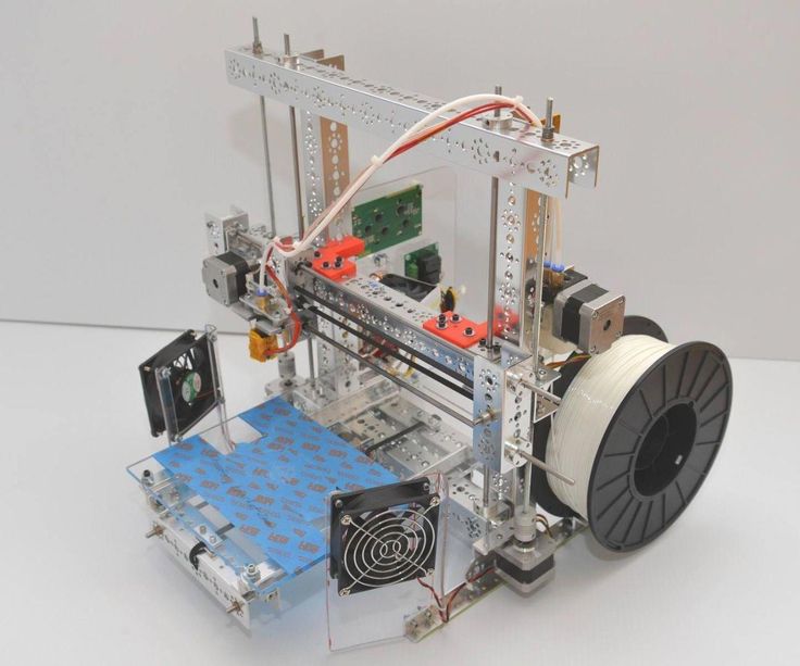
Good example of it is RepRap movement. RepRap is short for a Replicating Rapid-prototyper. In other words it is the self-replicating 3d printer. In fact most of today’s top consumer level 3D printers (picture above) are originated in one way or another from RepRap.
You can find a lot of examples on how to build a 3d printer from scratch on RepRap website, but we also want to describe some of more essential steps in order to give an overall understanding of what to expect if you really decide to make your own 3d printer.
The first step is to find and buy 3d printer DIY kit. Kits usually contain most of parts needed to assemble the printer and can be divided into two main types:
Scratch Built 3D Printer – This 3d printer DIY kit is for those who prefer to build thing from scratch, or in other words go to DIY RepRap route.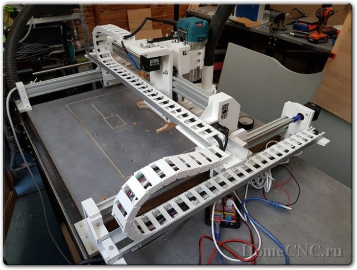 Apart from some essential advantages this approach has also its disadvantages. In theory it can save you some money and since you build it from scratch you will know every nut and bolt in it by the time you can use it and successfully print your first object. Main disadvantage of this method is time. Literally it will take a lot of time to deal with all these hundreds of bolts, wires, belts and much other stuff. In the end you still need to select and purchase or build a controller board, but it depends on your skills level.
Kit Built 3D Printer – This type of kit is good if you want to save some money and at the same time not to deal with all challenges described in the 1st kit type. Many manufactures sell such kits with “easy-to-assemble” instructions included. I doubt that it will be as easy as assemble a chair from IKEA, so you still have to be mechanically inclined and able to understand basic geometry. Some of such kits contain not all parts and you may need to buy something in addition.
The next step will be to determine the design for your 3D printer. In my humble opinion most of DIY 3D printers have not very breathtaking and futuristic design in comparison with MakerBot and other brands. But it is also a matter of taste, for some people the design is not very important.
Once you have got your 3d print DIY kit and chosen the design you could go ahead and start the most fascinating and time consuming part – build your own 3d printer. Be prepared for sleepless nights and a lot of fun. Maybe you will make up something new and present your findings to RepRap community.
When the hardware part of the 3d printer is ready you also need to add a software component to it. It basically does the following things: allows you to view and alter 3d graphical objects, as well as converts the 3d images into instructions that 3d printer can understand.
Finally you can 3d print your first object! If you do not have anything to print, you can find a big variety of objects on specialized marketplaces such as Shapeways, Thingiverse and others.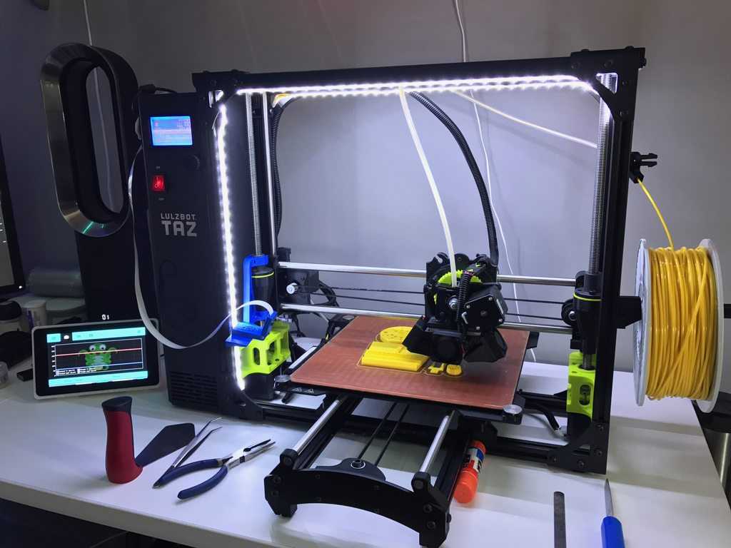 Before printing make sure that the object you want to 3d print has the right size and fit on the printer frame.
At the end there is a list of some links where you can find more information about how to build your own 3d printer from scratch:
- RepRap options
- 3D Printer DIY: How to Build Your Own 3D Printer from Scratch
- 3D Printing: Build Your Own 3D Printer and Print Your Own 3D Objects
- Arduino Controlled CNC / 3D Printer Hybrid
- El34 World – 3D Printer Build using 1 inch T-Slot extrusions
- CNET 3D Printer Build Week
Also watch a video from Ben Heck in which he answers on some 3d printing related questions.
Related Articles:
- What is 3d printing – 3D printing technologies overview
- What is 3D Printing?
- History of 3D Printing
- Direct and Binder 3D Printing techniques
- Photopolymerization and Sintering
- 3D Printing Process
- 3D printing revolution
- 3D Printing Materials
- How to choose a right 3D printer filament type
- 3D Printer Filament Types Overview
- Types of 3D printers or 3D printing technologies overview
- How to find and buy a right 3D printer
- History of 3D printing in one picture
- Places to download 3D printer files and files formats overview
- 3D Printing Services Overview
- You Should Know These Important 3D Printing Concepts
Homemade metal 3D printer, but something went wrong / Sudo Null IT News
Hello everyone, my name is Sergey.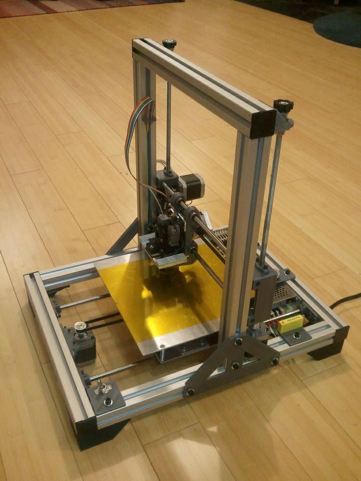 In this article, we will talk about 3D printing with metal, more precisely, about my attempt to implement 3D printing with metal.
Very often, people who are interested in or engaged in any activity, no matter what, stumble upon something completely new and previously unknown to them, something that can help develop/improve their main activity. A similar situation happened to me.
Surfing the expanses of your Internet, I came across a wonderful technology for vacuum deposition of metals on various materials. On Habré there is an interesting article about this technology. In addition, on many other resources it was said that the evaporated metal moves to the target in a straight line.
Lots of resources
ecm-zink.ru/info/stati/termicheskoe-vakuumnoe-napyilenie.html0003
And then I thought, what if I spray metal in the place I need, gradually increasing the thickness? I looked for information about whether someone did this - I did not find it.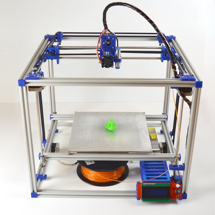
Registered on a forum where sprayers gather together and began to disturb them with questions like: is it possible to build up a “film” with a thickness of 1 or more millimeters. To which I caught a lot of misunderstanding what it was for, but received a positive answer.
General information received, you can begin to prepare for experiments.
It is known from various articles and documents that a vacuum of no more than 10⁻² Pa is required. For comparison, the order of magnitude - the pressure that gives a household vacuum pump (Value and others) - about 4 Pa (measured value), i.e. pressure is 400 times greater than necessary. How to deal with it and what to do? To achieve low pressures, turbomolecular vacuum pumps are used, they work in parallel with the foreline pump and, literally by molecules, capture the remaining air from the chamber. The process is not fast. The pump looks like this.
We installed a pump, it pumps out air and everything seems to be fine, but how to find out the pressure? For this I chose an ionization vacuum gauge.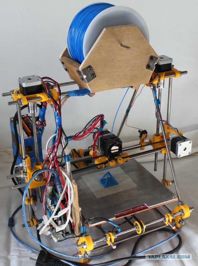
In fact, nothing else is needed, except for the chamber and evaporator. I did not find a ready-made affordable (in terms of finances) camera, therefore, I decided to make my own. It is of a small volume (about 8-10 liters) in order for the air to be pumped out faster. Usually, the chambers have a spherical shape, in my case it is, on the contrary, elongated, in order to be able to set the “target” (the place where the metal is deposited) at different distances from the evaporator. In addition, the camera has a lot of flanges for connecting all kinds of inputs/outputs and sensors. I modeled the camera in a well-known CAD program, drew drawings and transferred it to production.
Current leads and conductors I made from a brass bar and a brass rod, bought on the local market. (Juno, who is from St. Petersburg).
In the photo below, a tungsten boat is fixed between two conductors.
The bottom part looks like this. The photo shows the cooling tubes of the current leads.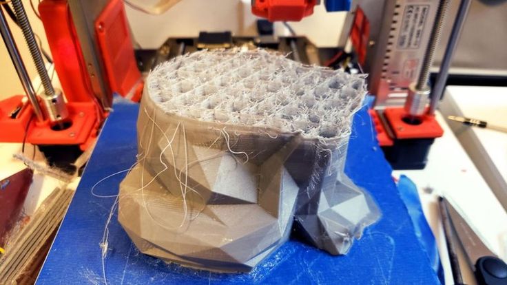 Subsequently, I abandoned them, due to the simplification of the system.
Assembling the camera did not take much effort and complexity. It is much more difficult to achieve vacuum retention in this chamber. To do this, I polished the flanges and all mating surfaces to avoid the slightest leakage through the rubber seal (in the photo below, I processed only the top flange).
As it turned out later, the weld is not airtight at all (meaning for low vacuum). I, out of inexperience, assumed that by pumping a pressure of 300 kPa into the chamber and immersing it in a bath of water, I would carefully find all the leaks and eliminate them. Yes, at the first stage I did just that, but the pressure in the chamber did not fall below 10-2 Pa, there were leaks. Interestingly, before the start of the test, at a pressure in the chamber of 300 kPa, bubbles emerged from the welds with an intensity of approximately 1 bubble (diameter 2-3 mm) in 30-40 seconds. And those were big losses that I eliminated.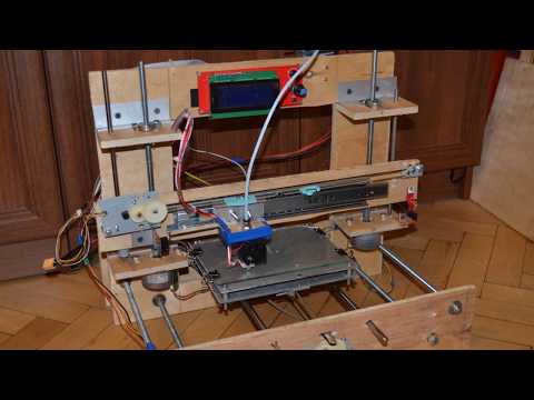 But what to do with minimal vacuum losses that cannot be tracked in "kitchen" conditions?
The solution was close. To do this, all you need is a mass spectrometer.
The idea is simple – the investigated chamber or container is connected to the vacuum chamber of the spectrometer. Air is pumped out, on the graph they look for extraneous peaks of any gases. After that, helium is supplied locally, to the places of possible leakage. It is helium, because its penetrating power is higher and the helium peak can be easily tracked on the spectrum. As soon as helium enters the chamber through a micro-hole, it is immediately visible on the spectrum.
I drove twice and looked for leaks twice. Now the chamber with the installed pump is hermetic and it is possible to carry out experiments further, having previously assembled all the components of the system on the rack.
General view of the incredible installation.
Starting up the plant and checking it comes down to maintaining the lowest possible pressure. The foreline pump is started first.
The pressure after the operation of the foreline pump can be seen in the picture below.
After the pressure is established (does not change). You can launch "heavy artillery" - a turbomolecular pump. It reduces the pressure by another 3 orders of magnitude.
The time has come for experiments, what I have been going for so long and what I have been waiting for so long.
First experiment.
Place a small amount of silver into the boat fixed between the conductors. Above the boat I install a steam conduit - a soldered tin cylinder, which, as I thought, should limit the spread of metal through the chamber. Above the steam conduit there is a lid with a hole of 2 mm, behind the lid there is a target on which the metal should condense. It is a pity that there are no photos left, but the vacuum chamber was completely dusty. There was not a single place where there was no applied layer of metal. In the photo below, it’s not a different planet at all, but silver sprayed onto the inner surface of the wall.
Second experiment.
I thought it was because of the large gaps between the boat and the steam line. The solution was born immediately and quickly. I took two boats and combined them so that a shell was obtained. I placed silver inside, and cut a hole with a diameter of 2 mm in the upper half.
And he began to heat up the whole thing. But, I did not take into account the rigidity of the boats and the rigidity of the current leads. The shells parted a little and a gap formed between them, through which steam also flew in all directions.
As a result - spraying in the entire volume of the chamber. In the photo below there is a viewing window, the boat in which was slightly above half, but the window was completely dusty.
Third experiment.
After a little thought and grief, I thought that the container with the evaporated metal should be airtight and with only one outlet, but how and what to make it. From tungsten - very expensive and difficult to process. The way out has been found! Graphite is an excellent material for making a crucible, let's call it that. On the ad site, I found an ad for the sale of graphite bars from the contact whiskers of a trolleybus, cut out a bar with a hole in the center and made a cover for it. In the photo below - just a bar with a hole for the material (without a cover).
And in this photo already in the chamber with the lid installed (the hole in the lid is 1 mm in diameter).
Under the spoiler are a few photos with a short period of time, from which you can see how dusty the viewing window is.
Loss of transparency
It is obvious that in this case, too, there was no success, to my great regret. All three experiments were carried out with a gradual increase in temperature from the state when evaporation does not occur.
A small video in which the information is presented in a slightly different way, in a different form and volume.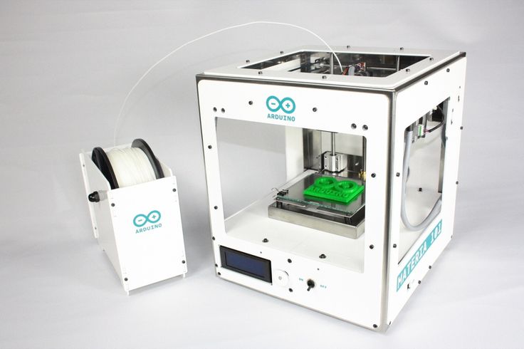
Video link
www.youtube.com/watch?v=4yWQOWIG1qw
Unfortunately, it was not possible to get what was intended, but, on the other hand, invaluable experience was gained in the design and manufacture of vacuum equipment. Most of this experience I have shared with you and I would be very grateful if you express your opinion on this issue.
Thank you all and good luck.
How to build a home 3D printer: recommendations from personal experience
3D printing and assembly of 3D printers is my hobby and passion. Here I will not share detailed diagrams and drawings, there are more than enough of them on specialized resources. The main goal of this material is to tell you where to start, where to dig and how to avoid mistakes in the process of assembling a home 3D printer. Perhaps one of the readers will be inspired by applied engineering achievements.
Why do you need a 3D printer? Use cases for
I first came across the idea of 3D printing back in the 90s when I was watching the Star Trek series.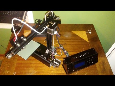 I remember how impressed I was by the moment when the heroes of the cult series printed the things they needed during their journey right on board their starship. They printed anything: from shoes to tools. I thought it would be great someday to have such a thing too. Then it all seemed something incredible. Outside the window are the gloomy 90s, and the Nokia with a monochrome screen was the pinnacle of progress, accessible only to a select few.
Years passed, everything changed. Around 2010, the first working models of 3D printers began to appear on sale. Yesterday's fantasy has become a reality. However, the cost of such solutions, to put it mildly, discouraged. But the IT industry would not be itself without an inquisitive community, where there is an active exchange of knowledge and experience and who just let them dig into the brains and giblets of new hardware and software. So, drawings and diagrams of printers began to surface more and more often on the Web. Today, the most informative and voluminous resource on the topic of assembling 3D printers is RepRap - this is a huge knowledge base that contains detailed guides for creating a wide variety of models of these machines.
I built my first printer about five years ago. My personal motivation to build my own device is quite prosaic and based on several factors. Firstly, there was an opportunity to try to realize the old dream of having your own device, inspired by a fantasy series. The second factor is that sometimes it was necessary to repair some household items (for example, a baby stroller, car elements, household appliances and other small things), but the necessary parts could not be found. Well, the third aspect of the application is "near-working". On the printer, I make cases for various IoT devices that I assemble at home.
Agree, it is better to place your device based on Raspberry Pi or Arduino in an aesthetically pleasing "body", which is not a shame to put in an apartment or take to the office, than to organize components, for example, in a plastic bowl for food. And yes, you can print parts to build other printers :)
There are a lot of scenarios for using 3D printers. I think everyone can find something of their own.
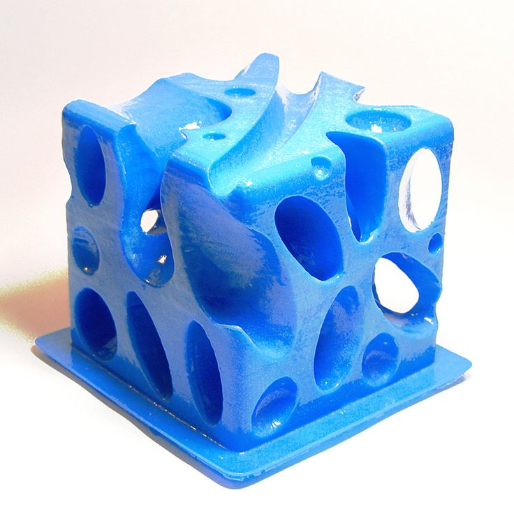
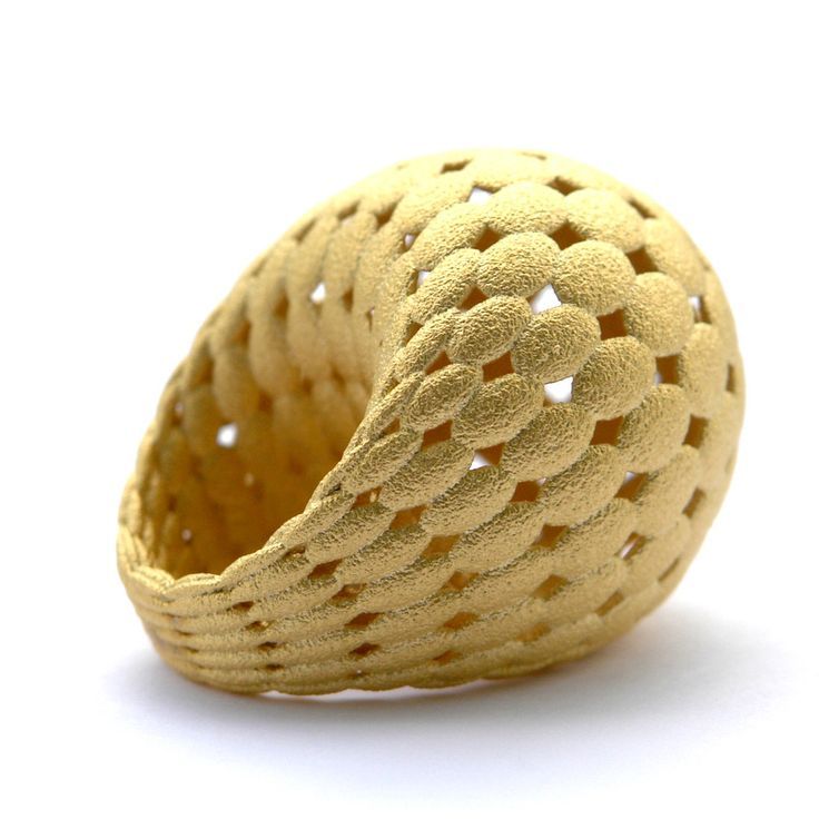
A complex part in terms of drawing that I printed on my printer. Yes, it's just a figurine, but it has many small elements
Ready solution vs custom assembly
When a technology has been tested, its value in the market drops markedly. The same thing happened in the world of 3D printers. If earlier a ready-made solution cost simply sky-high money, then today acquiring such a machine is more humane for the wallet, but nevertheless not the most affordable for an enthusiast. There are a number of solutions already assembled and ready for home use on the market, their price range ranges from $500-700 (not the best options) to infinity (adequate solutions start from a price tag of about $1000). Yes, there are options for $150, but we, for understandable, I hope, reasons, will not dwell on them.
In short, there are three cases to consider a finished assembly:
- when you plan to print not much and rarely;
- when print accuracy is critical;
- you need to print molds for mass production of parts.
There are several obvious advantages of self-assembly. The first and most important is cost. Buying all the necessary components will cost you a maximum of a couple of hundred dollars. In return, you will receive a complete 3D printing solution with the quality of manufactured products acceptable for domestic needs. The second advantage is that by assembling the printer yourself, you will understand the principles of its design and operation. Believe me, this knowledge will be useful to you during the operation of even an expensive ready-made solution - any 3D printer needs to be serviced regularly, and it can be difficult to do this without understanding the basics.
The main disadvantage of assembly is the need for a large amount of time. I spent about 150 hours on my first build.
What you need to build your own printer
The most important thing here is the presence of desire. As for any special skills, then, by and large, in order to assemble your first printer, the ability to solder or write code is not critical. Of course, understanding the basics of radio electronics and basic skills in the field of mechanics (that is, "straight hands") will greatly simplify the task and reduce the amount of time that needs to be spent on assembly.
Also, to start we need a mandatory set of parts:
- Extruder is the element that is directly responsible for printing, the print head. There are many options on the market, but for a budget build, I recommend the MK8. Of the minuses: it will not be possible to print with plastics that require high temperatures, there is noticeable overheating during intensive work, which can damage the element. If the budget allows, then you can look at MK10 - all the minuses are taken into account there.
- Processor board. The well-known Arduino Mega is well suited. I didn't notice any downsides to this solution, but you can spend a couple of dollars more and get something more powerful, with a reserve for the future.
- Control board. I'm using RAMPS 1.4 which works great with the Arduino Mega. A more expensive but more reliable board is Shield, which already combines a processor board and a control board. In modern realities, I recommend paying attention to it. In addition to it, you need to purchase at least 5 microstep stepper motor controllers, for example - A4988. And it's better to have a couple of these in stock for replacement.
- Heated table. This is the part where the printed element will be located. Heating is necessary due to the fact that most plastics will not adhere to a cold surface. For example, for printing with PLA plastic, the required surface temperature of the table is 60-80°C, for ABS - 110-130°C, and for polycarbonate it will be even higher
There are also two options for choosing a table - cheaper and more expensive.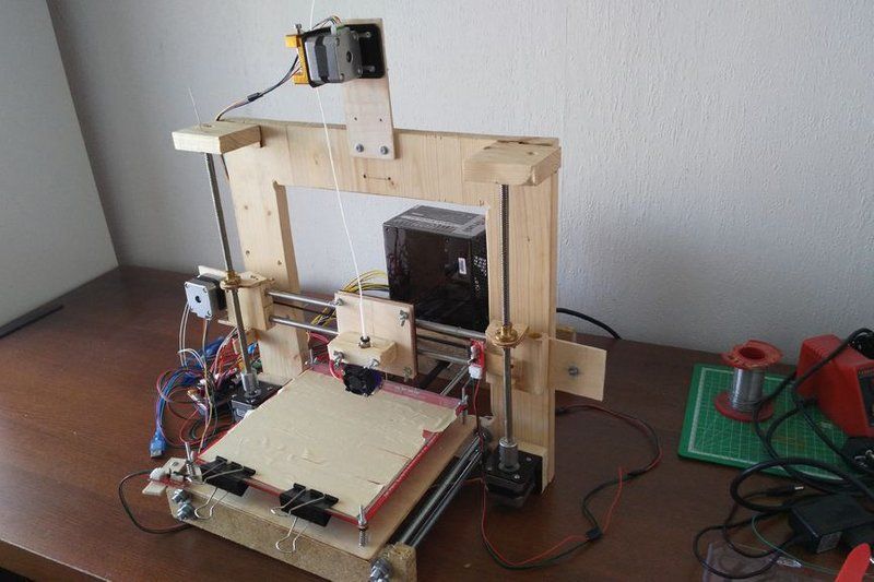 Cheaper options are essentially printed circuit boards with preheated wiring. To operate on this type of table, you will need to put borosilicate glass, which will scratch and crack during operation. Therefore, the best solution is an aluminum table.
 - Stepper motors. Most models, including the i2 and i3, use NEMA 17 size motors, two for the Z axis and one each for the X and Y axes. Finished extruders usually come with their own stepper motor. It is better to take powerful motors with a current in the motor winding of 1A or more, so that there is enough power to lift the extruder and print without skipping steps at high speed.
- Basic set of plastic fasteners.
- Belt and gears for its drive.
Examples of elements appearance: 1) MK8 extruder; 2) Arduino processor board; 3) RAMPS control board; 4) motor controllers; 5) aluminum heated table; 6) NEMA 17 stepper motor; 7) a set of plastic fasteners; 8) drive gears; 9) drive belt
This is a list of items you need to purchase. Hardcore users can assemble some of them themselves, but for beginners, I strongly recommend purchasing ready-made solutions.
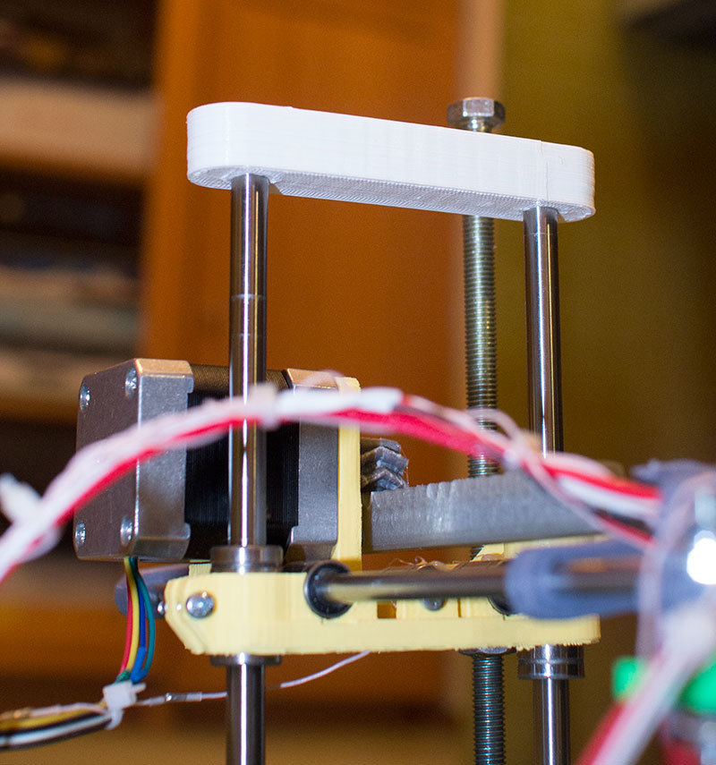
Yes, you will also need various small things (studs, bearings, nuts, bolts, washers ...) to assemble the case. In practice, it turned out that using a standard m8 stud leads to low printing accuracy on the Z axis. I would recommend immediately replacing it with a trapezoid of the same size.
M8 trapezoid stud for the Z axis, the use of which will save you a lot of time and nerves. Available for order on all major online marketplaces
Customized plastic parts for the X axis must also be purchased, such as these from the MendelMax retrofit kit.
Most parts available at your local hardware store. On RepRap you can find a complete list of necessary little things with all sizes and patterns. The kit you need will depend on the choice of platform (we'll talk about platforms later).
What's the price
Before delving into some aspects of the assembly, let's figure out how much such entertainment will cost for your wallet. Below is a list of parts required for purchase with an average price.
Platform selection
The community has already developed a number of different platforms for assembling printers - the most optimal case designs and the location of the main elements, so you do not have to reinvent the wheel.
i2 and i3 are key platforms for self-assembly printer enclosures. There are also many modifications of them with various improvements, but for beginners, these two classic platforms should be considered, since they do not require special skills and fine-tuning.
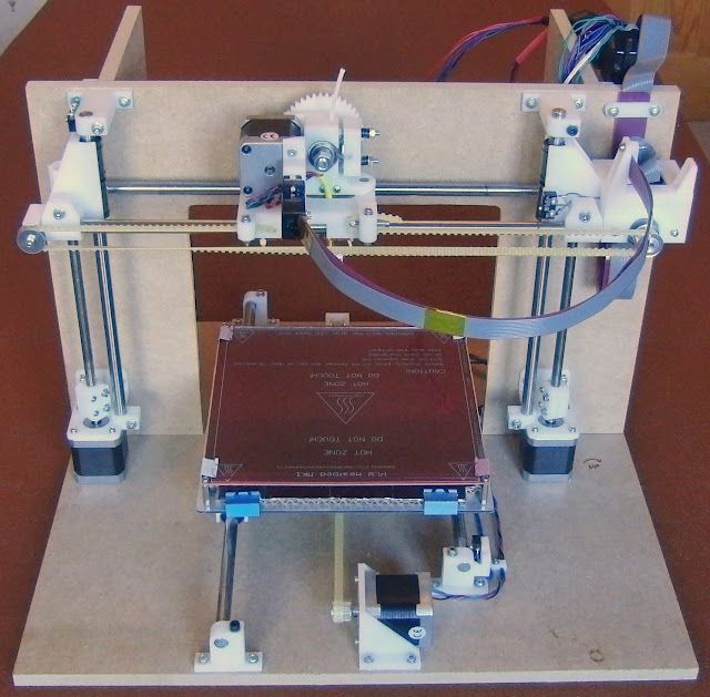
Actually, illustration of platforms: 1) i2 platform; 2) i3 platform
On the plus side of i2: it has a more reliable and stable design, although it is a little more difficult to assemble; more opportunities for further customization.
The i3 variant requires more special plastic parts to be purchased separately and has a slow print speed. However, it is easier to assemble and maintain, and has a more aesthetically pleasing appearance. You will have to pay for simplicity with the quality of printed parts - the body has less stability than i2, which can affect print accuracy.
Personally, I started my experiments in assembling printers from the i2 platform. She will be discussed further.
Assembly steps, challenges and improvements
In this block, I will only touch on the key assembly steps using the i2 platform as an example. Full step by step instructions can be found here.
The general scheme of all the main components looks something like this. There is nothing particularly complicated here:
I also recommend adding a display to your design. Yes, you can easily do without this element when performing operations on a PC, but it will be much more convenient to work with the printer this way.
Understanding how all components will be connected, let's move on to the mechanical part, where we have two main elements - a frame and a coordinate machine.
Assembling the frame
Detailed frame assembly instructions are available on RepRap.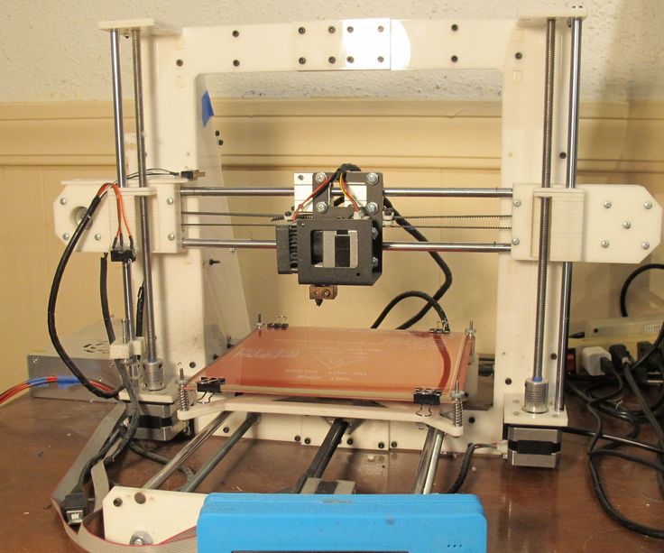 Of the important nuances - you will need a set of plastic parts (I already talked about this above, but I'd better repeat it), which you can either purchase separately or ask your comrades who already have a 3D printer to print.
The frame of the i2 is quite stable thanks to its trapezoid shape.
This is how the frame looks like with parts already installed. For greater rigidity, I reinforced the structure with plywood sheets
Coordinate machine
An extruder is attached to this part. The stepper motors shown in the diagram above are responsible for its movement. After installation, calibration is required along all major axes.
Important - you will need to purchase (or make your own) a carriage for moving the extruder and a mount for the drive belt. Drive belt I recommend GT2.
Carriage printed by the printer from the previous picture after it has been assembled. The part already has LM8UU bearings for guides and belt mount (top)
Calibration and adjustment
So, we completed the assembly process (as I said, it took me 150 hours) - the frame was assembled, the machine was installed.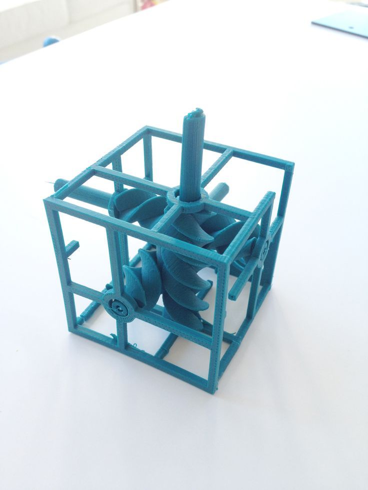 Now another important step is the calibration of this very machine and extruder. Here, too, there are small subtleties.
Setting up the machine
I recommend calibrating the machine with an electronic caliper. Do not be stingy with its purchase - you will save a lot of time and nerves in the process.
The screenshot below shows the correct constants for the Marlin firmware, which must be selected in order to set the correct number of steps per unit of measure. We calculate the coefficient, multiply it, substitute it into the firmware, and then upload it to the board.
Marlin 9 firmware constants0168
For high-quality calibration, I recommend relying on larger numbers in measurements - take not 1-1.5 cm, but about 10. So the error will be more noticeable, and it will become easier to correct it.
Calibrating the extruder
When the frame is assembled, the machine is calibrated, we start setting up the extruder. Here, too, everything is not so simple. The main task of this operation is to correctly adjust the supply of plastic.
If underfeeding, the printed test item will have noticeable gaps, like test die 1. Conversely, the result will look bloated if plastic is overfed (dice 2)
Getting Started Printing
It remains for us to run some CAD or download ready-made .stl, which describe the structure of the printed material. Next, this structure needs to be converted into a set of commands understandable to our printer. For this I use the Slicer program. It also needs to be set up correctly - specify the temperature, the size of the extruder nozzle. After that, the data can be sent to the printer.
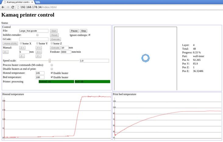
Slicer interface
As a raw material for printing, I recommend starting with regular ABS plastic - it is quite strong, its products are durable, and it does not require high temperatures to work with. For comfortable printing with ABS plastic, the table must be heated to a temperature of 110-130 ° C, and the extruder nozzle - within 230-260 ° C.
Some important details. Before printing, calibrate the machine along the Z axis. The extruder nozzle should be about half a millimeter from the table and ride along it without distortion. For this calibration, a regular sheet of A4 paper inserted between the nozzle and the surface of the heated table is best suited. If the sheet can be moved with little effort, the calibration is correct.
Another thing to keep in mind is the surface treatment of the heated table. Usually, before printing, the surface of the table is covered with something that hot plastic sticks to well. For ABS plastic, this can be, for example, Kapton tape. The disadvantage of adhesive tape is the need to re-glue it after several printing cycles. In addition, you will have to literally tear off the adhering part from it. All this, believe me, takes a lot of time. Therefore, if it is possible to avoid this fuss, it is better to avoid it.
An alternative option that I use instead of scotch tape is applying several layers of ordinary light beer, followed by heating the table to 80-100 ° C until the surface is completely dry and re-applying 7-12 layers.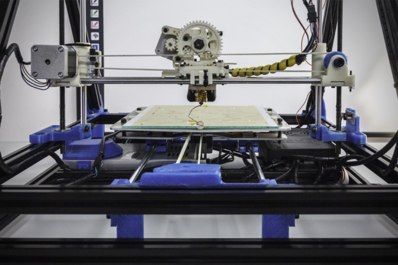 It is necessary to apply the liquid with a cloth moistened with a drink. Among the advantages of this solution: ABS plastic separates from the table on its own when it cools down to about 50 ° C and is removed without effort, the table does not have to be peeled off, and one bottle of beer will last you for several months (if you use the drink only for technical purposes :)).
After we have collected and configured everything, we can start printing. If you have an LCD screen, then the file can be transferred for printing using a regular SD card.
The first results may have bumps and other artifacts - do not worry, this is a normal process of "grinding" the printer elements, which will end after a few print cycles.
Tips to make life easier (and sometimes save money)
In addition to the small recommendations given in the text above, in this section I will also give a short list of tips that will greatly simplify the operation of a 3D printer and the life of its owner.
- Do not experiment with nozzles. If you plan to immediately print from materials that require high temperatures, then it is better to immediately take the MK10 extruder. On MK8, you can "hang" special nozzles that support high-temperature conditions. But such modifications often cause difficulties and require special experience. It is better to avoid this fuss on the shore by simply installing the right extruder for you.
- Add starter relay for heated table. Improving the power supply system of this important part for printing using a starter relay will help solve the known problem of RAMP 1.4 - overheating of the transistors that control the power of the table, which can lead to failure of the board. I made this upgrade after having to throw away a few RAMPS 1.4s.
- Select the correct media diameter for printing. I recommend using 1.75mm plastic for MK8 and MK10. If we take plastic, for example, 3 mm, then the extruder simply does not have enough strength to push it at an acceptable speed - everything will be printed much longer, and the quality will drop.
 ABS plastic is ideal for MK8, MK10 will be able to produce products from polycarbonate.
 - Use only new and precise X and Y guides. Print quality will be affected. It is difficult to count on good quality with bent or deformed guides along the axes.
- Take care of cooling. During my experiments with various extruders, the MK10 showed the best results - it prints quite accurately and quickly. The MK10 can also print plastics that require a higher print temperature than ABS, such as polycarbonate. Although it is not as prone to overheating as its younger brother MK8, I still recommend taking care of its cooling by adding a cooler to your design. It must be permanently enabled, this option can be configured in Slicer. You can also add coolers to keep the stepper motors at an acceptable temperature, however, make sure that their air flows do not fall on the printed part, as this can lead to its deformation due to too rapid cooling.
- Consider heat retention.
 Yes, on the one hand, we are struggling with overheating of the elements. On the other hand, a uniform temperature around the printer will contribute to high-quality printing (the plastic will be more pliable). To achieve a uniform temperature, you can put our printer, for example, in a cardboard box. The main thing is to connect and configure the coolers before that, as described above.
 - Consider insulating your desk. Heated table heats up to high temperatures. And if part of this heat leaves properly, heating the printed part, then the second part (from below) just goes down. To concentrate the heat from the table onto the part, you can perform an operation to insulate it. To do this, I simply attach a cork mouse pad to its bottom using stationery clips.
Pins
I am sure that during the build process you will encounter a number of difficulties specific to your project. Neither this text nor even the most detailed guides will insure against this.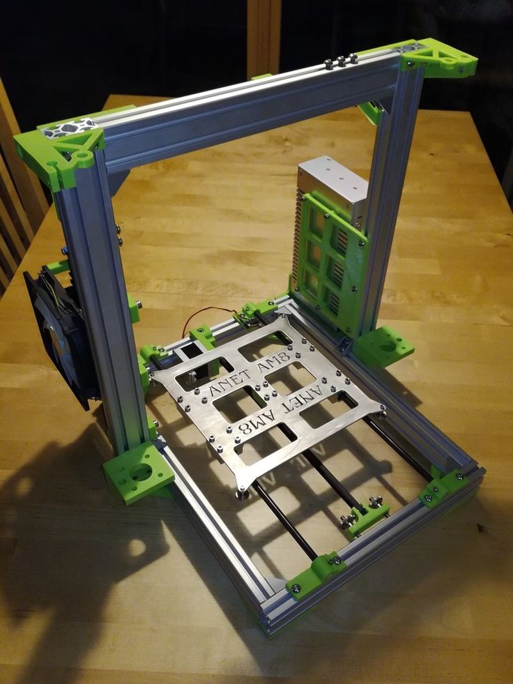
As I wrote in the introductory part, the above does not claim the status of a detailed assembly manual. It is almost impossible to describe all the stages and their subtleties within the framework of one such text. First of all, this is an overview material that will help you prepare for the assembly process (both mentally and financially), understand whether you personally need to bother with self-assembly - or give up on everything and buy a ready-made solution.
For me, assembling printers has become an exciting hobby that helps me solve some issues in home and work affairs, take my mind off programming and do something interesting with my own hands. For my children - entertainment and the opportunity to get unusual and unique toys. By the way, if you have children whose age allows them to mess around with such things, such an activity can be a good help for entering the world of mechanics and technology.
For everyone, the vectors of using 3D printers will be very different and very individual.