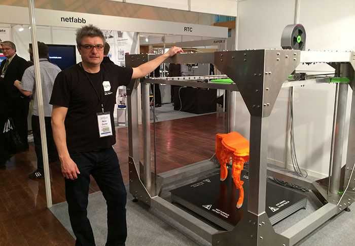
3D printer end stop
Endstops | Marlin Firmware
Endstops or limit switches are used on every moving axes of a 3D printer. The following chapter will provide information on:
- Purpose of the endstop
- Types of endstops
- Configuring endstops and probes
- Electromagnetic Interference / Electric Noise impact on endstops
Endstops fulfill two important functions in a 3D printer: Reference system for the axes system and safety.
Reference for the axes system
After powering up a 3D printer the printer’s controller board does not know at which position its axes are. Marlin indicates this by blinking question-marks in place of X, Y and Z on the LCD screen (v1.1.8 and older) or blinking ‘?’ in place of the coordinates besides X,Y and Z (Marlin v1.1.9 / v2.0.0 and newer).
This means the system needs first to establish its starting point of the physical (machine) coordinate system, a process called Homing. Homing can be initiated either via the G28 G-code or via the LCD controller.
Figure 1: LCD indication not homed axes (Marlin <= v1.1.8)
Safety
The other important aspect of an endstop is protecting the hardware from damage. Should any movement try to exceed the physical limits of the machine, the endstop will cut the movement.
There are two main types of endstops. Hardware endstops and software endstops.
Hardware endstops
Hardware endstops are electrically connected to the endstop ports of the printer control board and will provide a signal when the endstop condition is met.
Figure 2: Most common endstops (left to right): Micro switch, optical endstop (light barrier), hall sensor (magnetic)
Regardless of the type the basic way of working is the same:
- A typically 5 Volt signal (HIGH) drops to 0 Volt (LOW): Normally closed (NC) switch
- A 0 Volt signal (LOW) rises to 5 Volts (HIGH): Normally open (NO) switch
Probe as Z-Endstop
Probes can act like an endstop for the minimum Z-axis. While the typical endstop has a fixed position, the probe is mounted on the print-head and can freely move around the bed.
Figure 3: Common probe types: Inductive (left), solenoid touch probe (right)
Some aspects of probe configuration are considered in this endstop introduction. Further reading is provided in the Chapter Probes Configuration, Auto Bed Leveling and Unified Bed Leveling.
Software Endstops
Typically 3D printers are only equipped with hardware endstops on one side of each axis (Minimum or Maximum of the respective axis). As discussed above this is used to determine the starting point (origin) of the machine coordinate system.
In order to also protect the other side of the axes software endstops should be defined in the firmware via the #define MAX_SOFTWARE_ENDSTOPS / #define MIN_SOFTWARE_ENDSTOPS directive. This then uses the value from #define [XYZ]_MAX_POS / #define [XYZ]_MIN_POS to determine the maximum distance between the physical endstop and the software commanded stop of the axis.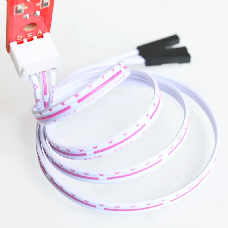 Software endstops can be (de-)activated via the M211 G-code.
Background
By default, slicers generate G-code that places the base of a printed model at z=0 and build upwards from there. The result of homing the z-axis should thus place the build surface at the z=0 plane. After homing in z, the hardware z endstop is deactivated (unless you have set ENDSTOPS_ALWAYS_ON_DEFAULT in Configuration_adv.h, which can be overridden by M120, M121), but to protect the hardware a software endstop is activated (which in turn can be overridden by M211 S0). This software endstop is located at Z_MIN_POS (defined in Configuration.h) . This is normally at z=0 at the nominal location of the bed. Note that when using bed-leveling, this software endstop is applied to the uncorrected slicer generated z-values. This allows printing into the hollows of the bed, where z < 0.
We now describe some common Cartesian printer configurations, with and without bed-leveling probes.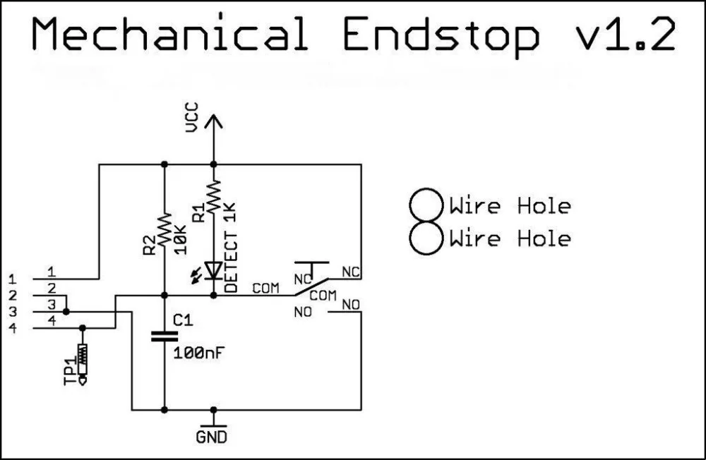
Microswitch endstop - no bed leveling probe.
Here we mechanically adjust the bed and possibly additionally the microswitch trigger point to level the bed surface as close as we can to the z=Z_MIN_POS (normally = 0) plane. The z location of the hardware (microswitch) trigger point defaults to the value of Z_MIN_POS. It is possible however to use a microswitch trigger point above the bed by setting MANUAL_Z_HOME_POS to the z-coordinate of the trigger point. See here. Having the trigger point below the bed makes little sense as the nozzle would crash into the bed before the microswitch triggered on homing.
Probe used for homing and bed-leveling.
The probe should be mounted so that its trigger point lies below the extruder nozzle. Z_PROBE_OFFSET_FROM_EXTRUDER (negative!) is this vertical offset. This offset is applied by the firmware when homing in order to properly reference the coordinate system to the nozzle position. To measure this see here. For a mechanical probe like a BL-Touch, this offset is geometrically fixed. For a remote sensing probe (e. g. inductive or capacitive), the offset might vary with bed material. You can tweak it using M851.
Figure 1: Example configuration using BL-Touch for both homing and probing.
The process of bed-leveling generates an array of z-values of the bed heights at the probed points. Marlin interpolates these values to estimate the bed height at any given x/y location. Figure 1 illustrates the situation. While probing, all endstops are turned off so that the probe can reach into the valleys of the bed. To protect the machine in case of the probe failure during probing set Z_PROBE_LOW_POINT to limit the probing depth.
Microswitch used for homing, probe for bed leveling.
When homing, the printer is not protected against hardware endstop failure. This configuration uses a perhaps more reliable microswitch for homing, reserving the probe for bed leveling, where Z_PROBE_LOW_POINT provides failure protection.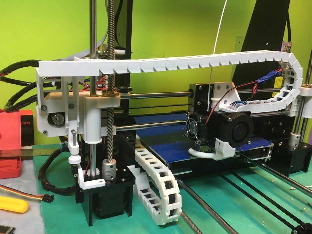 The configuration is illustrated in Fig. 2, requiring the use of both
 MANUAL_Z_HOME_POS and Z_PROBE_OFFSET_FROM_EXTRUDER Ideally, with an uneven bed, MANUAL_Z_HOME_POS should be adjusted so that z=0 lies halfway between the highest and lowest parts of the bed. This makes the maximum bed correction as small as possible.
Figure 2: Example configuration using a microswitch for homing, BL-Touch for bed-leveling probe.
Measuring offsets.
To measure an offset between a trigger point and the bed, lower the nozzle to the trigger point (by homing, if it’s the homing device), and note the z-value. Now turn off the software endstop temporarily (with M211 S0) to enable lowering the nozzle further down to the bed. Note the z again. The difference is the height of the respective trigger point above the bed.
Electromagnetic Interference (EMI) or electric noise, is an effect which can ruin the clean signal needed to properly and precisely measure electronically, be it temperature, endstop hits or any other value.
Sources and effect of EMI
In today’s life an abundance of sources for Electric Noise exists: Mobile phones, microwaves, WIFI, power supplies etc. There are also some prominent and strong sources of such noise in the 3D printer itself:
- Heated beds
- Hot ends
- Stepper motors
- PWM modulation
The Electromagnetic Interference created by these sources are picked up by other components, either because they are directly connected or via radiation. The useful signal needed by the other components will be disturbed or even altered so much that it is no longer useful.
Effect on endstops / limit switches
In the following HIGH = Logic 1 = 5 Volt will be used for a pressed switch and LOW = Logic 0 = 0 Volt for a not triggered switch.
Ideal endstop characteristic
Figure 4: Ideal Endstop
The above Figure 4 shows an ideal endstop characteristic: Once pressed it jumps from LOW to HIGH and the printer control board realizes this in virtually no time.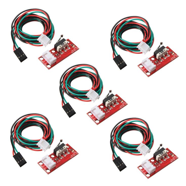
Real endstop characteristic with low noise
Figure 5: Real endstop characteristic
Figure 5 shows:
- There is no clean LOW or HIGH. Both states are somewhat unclean.
- Around the trigger point (marked in orange) a “bouncing” effect is shown: Due to mechanical influences the switch bounces between LOW and HIGH a few times before settling at HIGH.
- Bouncing is unwanted but in case of endstops not a show stopper
Real endstop characteristic with peak noise
Figure 6: Real endstop with EMI
This Figure 6 shows:
- Same characteristic as above but with a peak caused by EMI (marked in red)
- The peak is high enough to be falsely detected by the printer control board as pressed switch, potentially ruining a running print
Countermeasures
There are numerous countermeasures you can take to reduce noise:
- Use shielded cables / twisted cable pairs
- Apply careful cable routing (i.
 e., keep signal cables far away from power cables)
 - Enable software “debounce” filtering
- Add hardware filtering, such as a diode or capacitor
Options 3 and 4 are discussed further below.
Software Filtering
The code to deal with endstop noise is improved and exposed as a setting beginning in Marlin v1.1.9 and v2.0. In previous versions filtering is always active. To aid precision this is now exposed as a user setting in Configuration.h, deactivated by default.
/** * Endstop Noise Filter * * Enable this option if endstops falsely trigger due to noise. * NOTE: Enabling this feature means adds an error of +/-0.2mm, so homing * will end up at a slightly different position on each G28. This will also * reduce accuracy of some bed probes. * For mechanical switches, the better approach to reduce noise is to install * a 100 nanofarads ceramic capacitor in parallel with the switch, making it * essentially noise-proof without sacrificing accuracy.* This option also increases MCU load when endstops or the probe are enabled. * So this is not recommended. USE AT YOUR OWN RISK. * (This feature is not required for common micro-switches mounted on PCBs * based on the Makerbot design, since they already include the 100nF capacitor.) */ //#define ENDSTOP_NOISE_FILTER
Activating this option produces the following endstop characteristics:
Figure 7: Endstop with software filtering
The area marked in yellow in Figure 7 shows where software compensation is active. The first yellow area is a noise effect where the algorithm decides no endstop is triggered since the signal falls back to a LOW state.
The second yellow area shows a real, desired endstop trigger. The algorithm “watches” the situation for a few milliseconds before deciding if the endstop is really triggered or if an EMI / Noise effect needs to be compensated. This leads to a delay and some loss of precision in endstop detection.
Note
Depending on the printer’s geometry and the affected endstop, loss of precision may result in issues such as inconsistent bed leveling, so this feature is not recommended.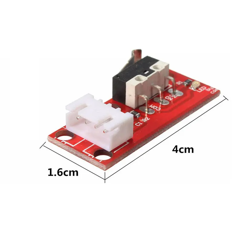 Instead, try to apply some kind of hardware filtering.
Hardware Filtering
Hardware filtering can range from an RC-unit (a simple capacitor in parallel to the switch over a resistor / capacitor combination) to opto-couplers and flip-flops.
Board
Some printer controller boards have built-in filters in the endstop connectors. Unfortunately the popular RAMPS v1.4 design does not, an oversight that’s been corrected with RAMPS v1.4.2:
Figure 8: RAMPS v1.4 vs v1.4.2
Endstop PCB
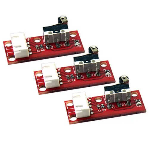
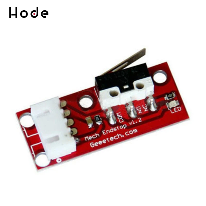
For 3D printing ready made filtered endstops are available, e.g. according to the Makerbot design:
Figure 9: Endstop PCB with RC unit
Endstop with capacitor
A simpler variant –easily fitted to endstops– is a 100nF capacitor, soldered over the two endstop connector pins (in parallel):
Figure 10: Endstop with 100nF capacitor
The Effect of Hardware Filtering
Figure 11 below shows the effect of hardware filtering: The noise level is smoothed and peaks are reduced so much that they no longer cause false readings.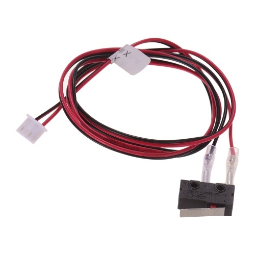 And the fast-bouncing signal at the initial trigger is dampened.
Figure 11: Endstop characteristic with hardware filter
Conclusion
Never underestimate electrical noise. It may be invisible but it can lead to strange and spurious effects that are tricky to diagnose. Simple measures (like adding a capacitor) will improve the situation a lot, improving the overall reliability of the machine.
Build a 3D printer - Part 8: Endstops
The stepper motors must know when they have reached the limits of an axis. For this purpose we use endstops.
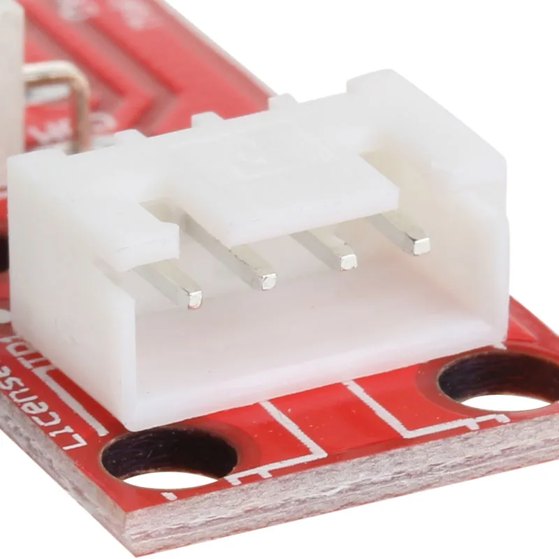
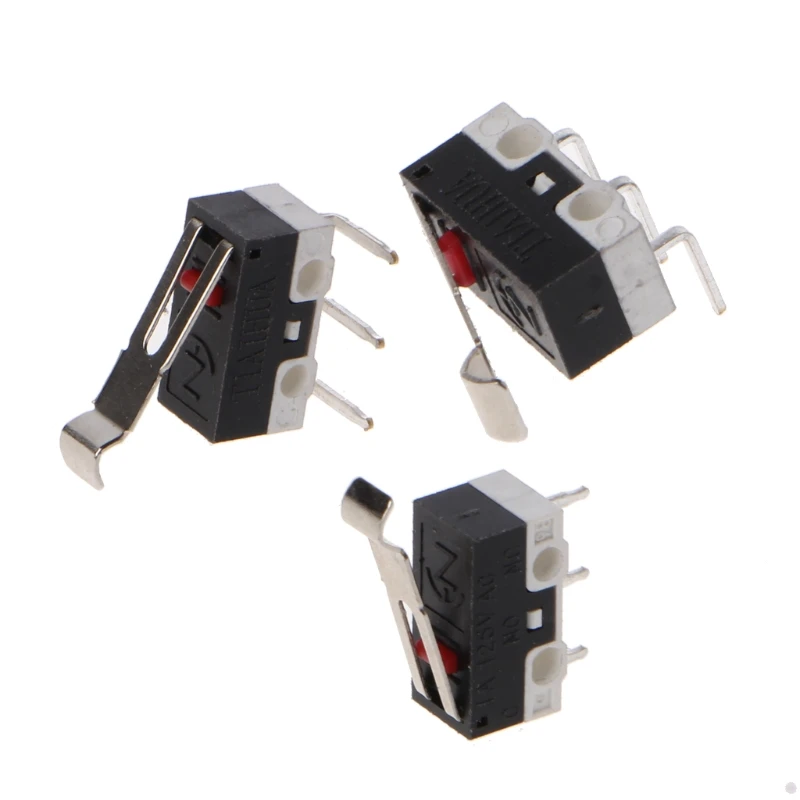
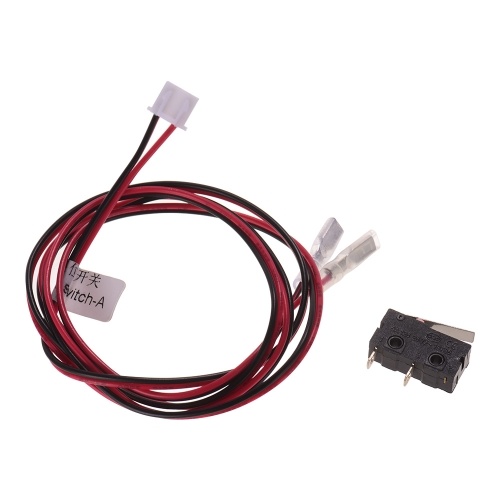
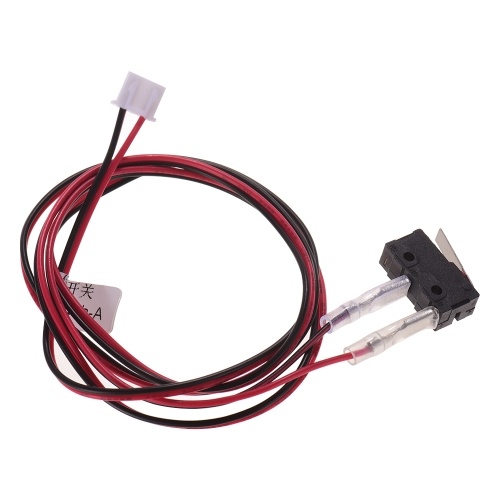
It theory it is actually possible to connect 6 endstops in a 3D printer. Two for each axis, but usually is it not needed as you only want to know when you have reached a zero point. Although it is possible to print outside the bounds, nobody minds it. An endstop is actually nothing else than a microswitch. Some companies have made nice PCB with controlling leds and connectors, but there is no immediate need fot that for the 3D printer.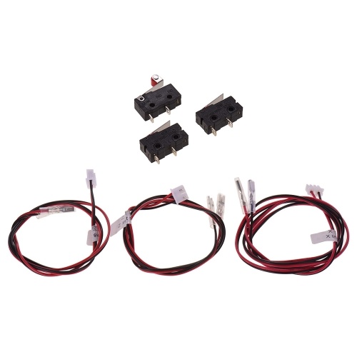 However, just to make things easier for yourself they are available. The endstops that I have used are designed by Makerbot and manufactured by Bigtree-Tech. The complete package includes the endstop and a cable to connect to the RAMPS 1.4 board.
The PCB also provides holes so it is easy to mount them on the frame. As I mentioned before you need 3 of them. To start with we have the Y-axis endstop. It is connected to the back of the frame, on the part called Y-MOTOR. In part 1 of this blog you can read more about this printed part. Connect this endstop just like on the picture below with 2x M3 x 12 mm screws, nuts and washers. The bed platform must be able to press the switch when it is all the way to the back.
The next endstop that we will cover is the X-asis. Because the standard part provided in the Prusa i3 Rework collection is actually connected on the right side to the X-axis idler and we are not using it, we need to print an extra part. Download and print this X-axis endstop mount. It is actually from the P3steel project, but it will fit just fine on our Rework frame. Connect the endswitch PCB with 2x M3 x 12 mm screws to this part.
Now you can click it on the 8 mm X-axis bars and slide all the way to the left. The connector and cable will point to the top, which is actually a good thing. I guess it is also possible to place it on the right of the frame, and use it as max-endstop. Or even just like in the original Rework project a "negative" 0-endstop. It will all become clear as we will start to confiture the Marlin firmware. There are settings in the code where the position of the endstops can be configured.
The last, and in my opinion the most fun endstop to make is the Z-axis endstop. There are countless possibilities and projects that solve the problem of this endstop. Among many they include optical, magnetic or even proximity sensors that will enable to find the zero position of your Z-axis. In our case we will use the same switch as for the other axes.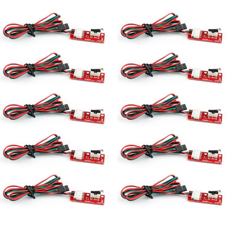 One of the best projects that I could find was the Z endstop easy adjustment kit for Prusa mendel i3. It consists of two parts. One of the parts is attached to the Z-motor mount. This is also the place for the endstop switch. Mount it like on the picture below.
The other part of the endstop is placed on the X-axis stepper motor. It provides a hole for a M3 screw where you can make easy adjustments for where the Z stepper motor needs to stop rotating. Place a spring between the screw and the printed Z-endstop-moving part. I have actually used a spring from a pen. In my case the M3 screw was 50 mm in length. Do not forget to place a nut on the other side to hold the screw in place.
We have reached the point where we have installed all the mechanical parts in our 3D printer. In the next parts we will cover the heated print bed and electronics.
Category
Answers to questions on endstop
Switch used to notify the controller that the printer has completed its home travel.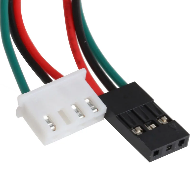 Also known as a limit switch.
Used on all three axes to indicate to the controller that the desktop or printhead has reached the end of its home travel. This allows the controller to get a zero point while moving, which provides a home position during printing. nine0003
There are three main types of end posts (or limit switches):
The mechanical switch is just a simple on/off device. When the table or print head is moved to the desired location, a metal lever is pressed against a switch that indicates and sends a signal to the controller.
Optical switch - This type has an optical beam which, when interrupted, sends a signal to the controller. nine0003
Proximity sensor - most commonly used on the z-axis for table alignment. When the end of the sensor approaches the table, it sends a signal to the controller before the sensor comes into contact with other parts of the printer.
- Flashforge Adventurer 3 - how to replace the x-axis stop I found a similar question on the forum, but now I need help replacing the x-axis stop.
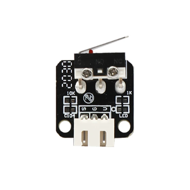 I searched for a video and did not find it yet. Can anyone help me? The printer turns on, warms up, but as soon as I ...
 - How to align the kossel endpoints? My printer is kossel (delta 3d printer). I have a probe far from the nozzle (offset -x45 y17), every time I run a G29 the result is unacceptable, the distance z between the points is greater than 0.5mm,…
- I have an old Solidoodle 2 that I bought broken at a garage sale and that I am converting to use RAMPS 1.4 with Marlin firmware. All engines are working properly, I have ...
- 3D printer affected by forced movement over limit A faulty endstop caused the printer (traditional Cartesian FDM) to try to go over the maximum axis limit from above, the noise was terrible, I don't see any damage (apparently) but I'm wondering ,…
- Ender3 V2: What stops Y? Since there is no limit switch at the Y (Y -) operator end, what stops it from moving when printing?
- Problems with Marlin 9 firmware0029 So I'm working on making a Prusa i3 MK3 clone and so far everything has been going well, but when I make changes to the firmware and re-download it, the printer doesn't seem to get it.
 For example, I changed…
 - Ender 3 - X Axis Can't Reach True Home After a year of printing smaller models, I finally went to print something that would take up most of the build plate from left to right and realized that my nozzle was not can reach "true" X home. As you can see…
- BigTreeTech mini e3 V1.2 endstop installation I recently bought a BigTreeTech mini e3 V1.2 controller for my own 3D printer (as opposed to a pre-purchased ender 3). In doing so, I ran into a problem that the endpoints,…
- Limit switch problems on RAMPS 1.4 and a custom 3D printer running Marlin 1.1.0-rc6 So I'm trying to fix a custom 3D printer for my institute and I'm running into a problem that I can't figure out. Thus, the limit switches for the Y and Z axes…
- 3D printer endstop does not fire in Pronterface when pressed I am using Makerbot end stops connected to a RAMPS 1.4/Arduino Mega 2560 setup. I am using Marlin and Pronterface firmware.
 When I send an M119 command, all six (I use max - and…
 - Z homing problem on Ender 3 Pro with Marlin I just changed the motherboard on my Ender 3 Pro to MKS GEN_L v1.0 and flashed it Latest version of Marlin. I manually calibrated the table using the standard XY and Z auto home commands on…
- Ender 3, why only 3 limit switches? Why does Ender 3 only have 3 limit switches instead of 6? How does he deal with accidents on the other sides? Should I add them with a new motherboard?
- How to properly set house offsets and manual house definitions in Marlin? I'm using an Ender 3 and just upgraded to a Hero Me Gen 5 fan airway adapter. This caused the nozzle position to shift. I also flashed some new Marlin 2 firmware, and in…
- Y-min stay triggered I have a FLSUN i3 220x220x240 with: LCD Display Year 2004 (RepRap Discount Smart Controller) MKS-gen-L-v1.0 printer board runs Marlin 2.0 firmware…
- How do MAX endstops work? I am building my new 3D printer and I have doubts.
 I use limit switches on 3 axes, but only on minimal switches. I also have three more switches that I want...
 - Stepper motor homing as an extruder using E0/E1 with limit switch and end stop Note: I expanded my question as some of you mentioned that this question is not entirely clear. I am using a RAMPS 1.4 board with an Arduino mega 2560. I need to control a stepper motor in…
- Z axis end stop not working after installing Marlin firmware I have had my Monoprice Maker Ultimate for a few months and have started making updates to him. My latest change is to update the firmware to a newer version of Marlin,…
- What is this part and does it have anything to do with the fact that the z-position is broken? I recently bought my first monoprice maker select v2 3d printer. After a few print jobs, this piece fell out. I have no idea where he came from. But then I notice that...
- My homemade printer only boots when all of my endpoints fire.
 Why is this? Recycling a Robin nano board for 3D printer assembly using an old computer power supply (300W), it only boots when I have no end stops at all or if I…
 - Which endpoints are most accurate? I have seen mechanical (microswitch), optical and magnetic (magnet + hall sensor) end stops. Are there any differences in how accurately they switch in the right place? If...
- Reprogram Marlin to assign end pins for arbitrary tasks [Arduino Mega] Can someone point me to the appropriate input code for this task in the Marlin source code?
- Does moving the z-stop up affect the maximum height of the printed object? Since moving the stop up reduces the range of the z-axis, I was wondering if this reduces the maximum printable height by the distance the stop was moved. Or is it…
- Home E / extrude until the stopper works I'm working on something that I'll share as soon as it's done (hope it really helps someone then).
 This requires the stepping mechanism to rotate the part by a certain...
 - Tevo tarantula Z - port burned out I burned Z - port for Z-terminus. Can I use the Z+ port? I'm using Jim Brown's Marlin Firmware. Any help in changing this is greatly appreciated. I don't know anything about the code.…
- Z Axis TEVO Tarantula Drops Too Far After End Stop Triggered A problem with z axis homing is giving me an ulcer. I hope someone can help with this. As usual, after the Z-stop is activated on my TEVO tarantula, the portal rises a little ...
- MKS board loses power after installing end stop I just bought MKS gen v1.3 and everything works fine except when I connect endpoints. My X end stop works great in every outlet, but when I...
- Is cutting off the lever from the Z axis switch a good idea? We all know (or should know!) that the repeatability of conventional spring-arm limit switches is crappy at best.
 I'm about to build and install one of the precision regulators...
 - Z axis goes down and presses on the table while printing I am using a Prusa i3 with Marlin firmware. All components of my 3D printer are working fine. I have a problem with my z-axis, it goes down and presses against the table. I tried to adjust…
- Cannot install auto table leveling sensor in Anet A8 I tried to install an inductive automatic table leveling sensor in my Anet A8 and had a few problems. I used the wiring diagram provided by Solid...
- Connection of Sain Smart mechanical end stops to RAMPS 1.4? I have Sainsmart mechanical end stops and am building a Prusa i3 conversion. I recently made the x-axis move, but it should stop when it reaches the end, and it doesn't; in…
3D printer parts optical end light control optical end switch for 3D printers RAMPS 1.4 with cable
Share to:
- Description
- Reviews (1)
- Delivery and payment
- Bulk request
Descriptions
- Optical end stop is a reliable end stop/switching solution for any type of 3D printer and others
- CNC and/or 3D tools
- 100% brand new and high quality
- Quantity: 1pc
- Weight: 8g
- Color: as picture show
- Size: 32mm x 10mm / 1.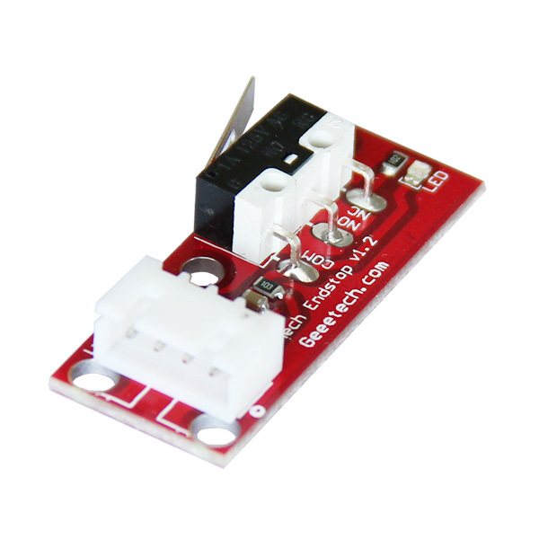 26 x 0.39(inch) (approximately)
- Optical limit switch
- Optical limit switch optical switch 3D printer shifter
- And supports the use of RAMPS 1.4 plate
Specification
- All (1)
- Photo (0) nine0031
- Video (0)
- Sort by: All
All Popularity Most Helpful Most Recent
-
Translate to English
-
Caselli
Yes (0)
Interruttore ottico di fine corsa costati poco peccato che non c'è nessuna istruzione per la cablatura si deve fare ricerca su internet
Jun 11,2019
Do you want to buy in bulk ? Please submit your wholesale inquiry below.