3D printed ear saver
Lessons From the Field – 3D Printed Ear Savers
By simplify3d
In COVID-19
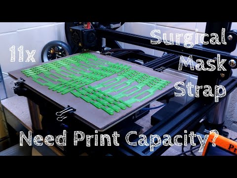
Many of us have seen images of healthcare workers who’ve taken their mask off after a 12-hour shift. Their faces are covered in red lines and wrinkled skin from the pressure created by the elastic bands required to secure a respirator or surgical mask to their face. What you don’t see in those images is the irritation behind their ears from the strapping on the masks. Many users of masks also report headaches, chafing, and even blisters during prolonged use. In response, the additive manufacturing community has developed 3D printed tension relief bands for masks that help to alleviate many of these problems. In this post, we’ll share best practices for printing these ear savers.
Select an Approved Design
On the NIH Print Exchange, there are several models of ear-savers. Each design has the same purpose, to capture the mask strapping that normally loops around the user’s ears and distribute the pressure across the back of the head.
When selecting a design keep in mind that the size, shape, and rigidity of the band will impact how it feels in use. You may find that some designs work better for your particular mask or respirator. With short print times and low material cost, consider printing several of the designs to figure out which one works best for you.
Surgical Mask Tension Release Band – This tension relief band strikes a balance between comfort and utility. The slightly curved frame is durable and flexible while maintaining four options for adapting the fit.
Surgical Mask Band for Ear Comfort – Extra Security V2 – This design captures the mask strap with hooks set at four intervals. This is a useful feature when taking a mask on and off frequently. We found that the overhang created by the hook requires printing supports with the part.
Ear Saver for Surgical Mask – This efficient model prints very quickly and is extremely lightweight. We suggest using this design if you need a long strap that can be disposed of at the end of the day because of the low material usage.
Mask Comfort Strap – This bone-shaped design is very simple and potentially disposable because of how fast it is able to be printed. This design is not adjustable and its default size is much shorter than other designs. This design is particularly useful if you are looking to create additional tension in your mask straps.
Source your Materials
Ear savers can be printed in nearly any filament type. By design, they are thin parts that conform to the back of the user’s head or neck. We found that filaments like PLA, which are not traditionally known to be a flexible filament, can be used to produce ear savers because the designs are so thin. We recommend avoiding filaments that warp heavily, like ABS, and materials that may have abrasive properties, like metal or wood-filled filaments.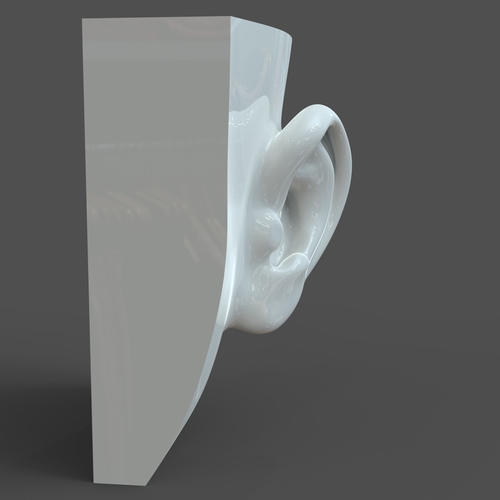 If you need additional information about a filament material, our Ultimate 3D Printing Materials Guide can help you get started.
The only other item you might want to have on hand is the mask or respirator that you will be using with the ear saver. You will likely want to test the fit of your device paired with the ear saver before finalizing your design decision, so make sure you have these items handy.
Optimize your Print Settings
We’ve gathered some best practices from the field to help you optimize your production efforts.
- Increase the Perimeters
- Adding an additional perimeter to your ear saver will make the mask strap connection point stronger.
- Increasing from 2 to 3 perimeters will provide the necessary additional strength.
- Read more about thin walls and small features in this in-depth article.
- Increase the Number of Top and Bottom Layers
- Most ear saver designs have 10 or fewer layers when printing at 0.
 2mm layer height. By increasing the number of top and bottom layers from 2 to 5, the part will be printed with 10 solid layers instead of adding fill layers between the top and bottom layers.
 - A solid layer will increase the strength of the part by avoiding infill intersections along the width of the band. These intersections have a higher tendency of failure during repeated use.
- Most ear saver designs have 10 or fewer layers when printing at 0.
- Fill the Print Bed
- A single tension relief band can be printed in about 15 minutes. We suggest filling your print bed to optimize production. The goal is to spend less time starting and removing prints and more time printing.
- Once you import a model, Ctrl+D (or Cmd+D on the Mac) will create duplicates on the build table.
- Click ‘Center and Arrange’ under the Model List to arrange your parts.
Putting your Print to Use
Ear savers are simple parts that are nearly ready for use as soon as they are done printing.
- Removal from Print Bed
Ear savers are thin parts that require care when separating them from the print bed so that they don’t permanently bend while still warm.Allow the print bed to cool before attempting to separate the ear saver from the print bed or remove the ear saver by using a low-angle scraper to gently pry the part off the print bed.
- Disinfect
The last step is to disinfect each band with a 10% bleach solution for 5 minutes to remove any contamination. The CDC has helpful tips about disinfection methods on this page.
- Distribution
Ear savers will improve the day-to-day life for anyone who has to use a face mask for an extended period of time. We suggest calling medical facilities in your area to see if they can use 3D printed ear savers and then check with your social circles for individuals who could benefit from them.
Are you helping in the fight against COVID-19 using 3D printing technology? If you have participated in 3D printing efforts to support health care workers or know of new ways additive manufacturing is being used to combat COVID-19, please share your story with us at stories@simplify3d.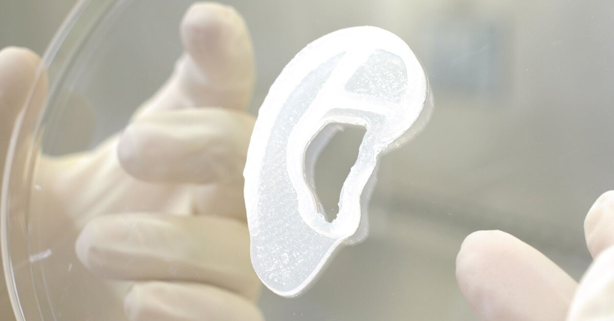 com.
com.
3d Printed Ear Saver - Etsy.de
Etsy is no longer supporting older versions of your web browser in order to ensure that user data remains secure. Please update to the latest version.
Take full advantage of our site features by enabling JavaScript.
Find something memorable, join a community doing good.
(74 relevant results)
Customized ear tips - 3D printing
3D printing is used extensively in many industries.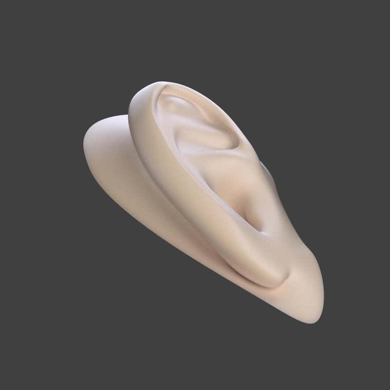 It has become indispensable in the production of hearing aids and their parts. In particular, with the help of modern additive technologies, individual ear plugs are made.
Medicine and prosthetics have come a long way, and now hearing aids are used to solve hearing problems of I-II-open prosthetics and III-IV-closed prosthetics. In this case, a variety of techniques and devices, made individually, are used. nine0003
The custom earmould is an in-ear anatomical element that provides a perfect connection between the hearing aid and the ear. A distinction is made between earbuds that serve only as an adapter (connected with a tube to a behind-the-ear hearing aid), and products with a built-in device.
Manufacturing process
Individually made earmoulds are made in several steps:
- impression;
- scan;
- creation of a digital model of the ear canal;
- simulation;
- product printing;
- processing.
The production of earmoulds starts with an impression.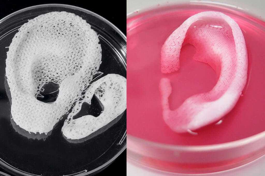 An ottoblock is inserted into the patient's ear and a special silicone mass is injected. It quickly hardens and a ready-made anatomical cast of the ear is obtained. This impression is placed in a 3D scanner, which allows you to digitize the workpiece and get an accurate three-dimensional image of the ear canal.
An inlay is modeled in a CAD program, which is then sent to a 3D printer for printing. The resulting product is additionally processed: it is cleaned, polished, the necessary holes are made. nine0003
The earpiece can be completely discreet and can be inserted directly into the ear canal. There are also products that occupy half of the auricle or its entirety. These parameters are determined directly by a specialist.
What materials are used for earmoulds
There is a wide range of materials that are used for printing earmolds. These are, as a rule, liquid photopolymer resins that allow the production of transparent or colored products. Depending on the requirements, the liners can be soft rubber-like or hard. In accordance with this, a photopolymer is also selected. For example, specialized photopolymer resins from EnvisionTEC can be used:
- E-Shell 200
- E-Shell 300
Of course, serious requirements are imposed on materials: hypoallergenicity, biocompatibility, durability. A wide color palette allows you to choose the best option. It is possible to manufacture earbuds that are firm in the hands, but become elastic in the ear when heated from the body, which ensures maximum wearing comfort and invisibility of their use.
Benefits of 3D printing in audiology
3D printing and 3D scanning allows you to achieve maximum precision of the earmoulds and match the anatomical features of the patient's ear. In addition, the advantage is the reduction of production time and cost of products. All this together serves to improve the comfort and quality of life of people with hearing impairments.
On average, an individual earmold lasts about 1. 5-2 years with proper care. It is resistant to wax, sweat, etc. In children, due to their growth, replacements must be done more often. Thanks to new 3D printing technologies, this is not a problem. And if you purchase a 3D printer, then once you have completed professional modeling, a person can, if necessary, print ear molds for hearing aids with his own hands. nine0003
Customized Silicone Eartips and Form 2
Quick Overview
Customized Eartip provides a very secure and comfortable fit for applications such as hearing aids, music in-ear headphones, high-end headphones and hearing protection, but customization can get real problem.
Digital scanning technology and software make it easy to capture and modify the natural shape of a unique human ear canal, while 3D printing provides similar benefits. Digital manufacturing provides more control and precision than traditional manufacturing
Traditionally, digital manufacturing processes have been costly for all but a few large earmold labs. Now, with technologies like the Form 2, an affordable high-resolution stereolithography (SLA) 3D printer, earmould labs of all sizes can transition soft silicone earmolds to a digital manufacturing process.
This white paper, developed in partnership with The Listening Stack, describes how to make custom silicone earplugs using the Form 2 and Formlabs standard clear resin. By integrating this digital manufacturing process, Listening Stack owner Justin Stack estimated that the company achieved a 40% reduction in rework, resulting in significant cost and time savings for his company. nine0003
Introduction
Audiology applications are a natural fit for mass customization in 3D printing. The inside of each person's ear is made up of extremely unique organic shapes and curves. The ear tips must fit perfectly to ensure optimal sealing and performance of the end device.
Traditionally, custom earmoulds are made using a laborious process that requires several different casting and manual processes. Over the last decade, custom inlay manufacturing has largely shifted to a digital manufacturing process. Digital editing and 3D printing of each individual insert results in more consistent quality, accuracy and better product control. nine0003
Many larger labs are already using 3D printing in their earmold technology. While the process is relatively well established, the cost of high-precision printers has made additive technology out of reach for smaller labs. As a result, many laboratories still use the traditional injection molding approach, while others choose to outsource production.
This booklet describes the process of molding a custom silicone earmould from a shell that has been printed on a Form 2 Stereolithography 3D Printer (SLA). This process has been successfully used by Form 2 users such as The Listening Stack, an earmould lab and hearing aid manufacturing center that provides patients with hearing aids, personal hearing protection and in-ear headphones. nine0003
Fig.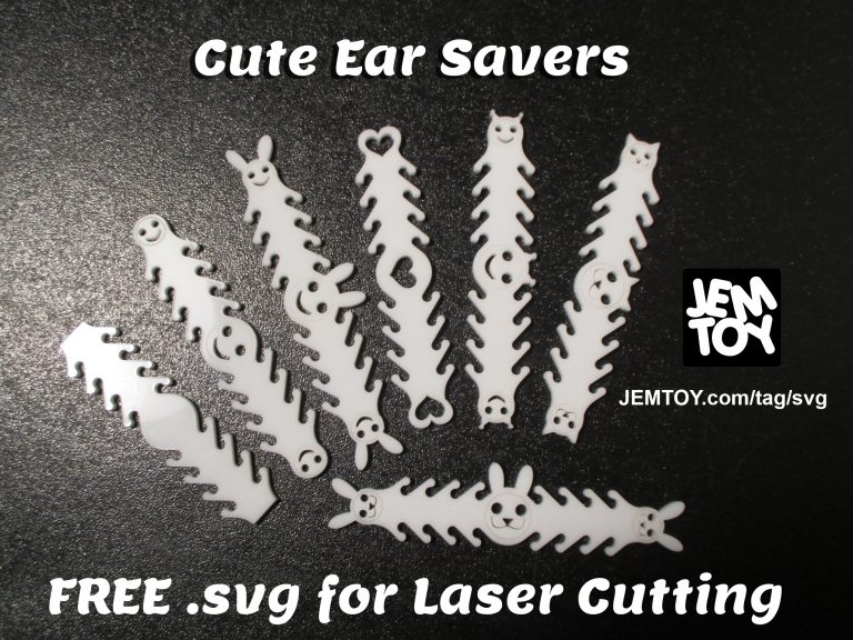 1: Silicone earmold molded from a print made on Form 2.
2: Soft and hard ear tip.
Digitalization of earmoulds
Custom earmoulds come in several different designs and materials depending on the application, and are usually either in the rigid (usually acrylic) or soft (usually silicone) category. 3D printing provides efficiency for making both types of inlays with two slightly different printing technologies. nine0003
Traditionally, custom earmoulds and shells are made by hand by varying the roughness of the impression (material removal, sanding and polishing) and adding layers (wax dipping). The impression is then used as a master mold to create a negative cast from another material, which is then filled with the final liner material. If the liner is a solid acrylic material, it is then cured in a UV curing oven. If the liner is made of soft silicone, it is post-processed in a pressure curing machine and requires special skills and experience to ensure consistently high product quality. Because the process is largely manual, human error makes the task more difficult and rework is common. nine0003
With 3D printing, the impression can be scanned and digitally modified on a computer, reducing the chances of human error and the need for physical effort. Scan results can be saved and modified instead of collecting new impressions to correct an error or create a new inlay. The files are then 3D printed as rigid earmolds for direct use in the ear, or as a shell for the injection of a softer material, which is then used as the final product. nine0003
The end product is more accurate and consistent, requiring fewer rework and more control for technicians.
The benefits of the digital process also affect the overall efficiency of a company, as files can easily be stored for years and do not require physical storage or maintenance. This allows for optimal patient record keeping and economies of scale when creating more than one insert.
How to use the Form 2 to make custom soft earmoulds
Form 2 provides new opportunities for earmould labs that want to move from manual processes to more accurate and consistent digital workflows.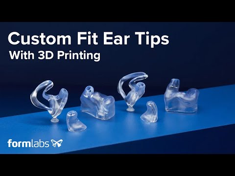 The Listening Stack already uses the Form 2 to make nearly all of its custom earmolds.
The following sections describe The Listening Stack's end-to-end process for making soft full-shell earmolds.
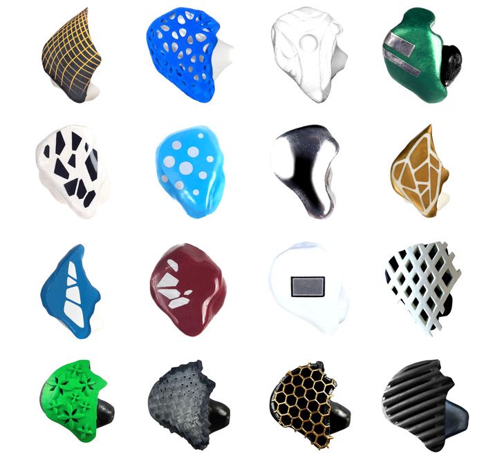
This process uses what is often referred to as "eggshell technology" where companies print a hollow shell version of the earmould that is then filled with silicone to produce a conventional soft earmould. The imprinted molding cracks from the inserted silicone earmould, similar to the cracking of a hard-boiled eggshell. nine0003
Fig. Figure 4: Earmoulds molded from Form 2 impressions.
Workflow
1. IMPRESSION
An integral part of the manufacture of any custom earmold is taking an impression of the inside of the patient's ear. To do this, an audiologist or hearing care professional uses a syringe to infuse an impression material into the ear, usually in the form of a liquid/powder mixture or silicone.
Excessive spread of material in the canal is usually blocked with an otoblock, which is a small piece of foam or cotton that is placed in the ear prior to injection. After injection, the material hardens within three to five minutes and the impression can be pulled out. nine0003
Fig. 5: Obtaining an impression of the ear.
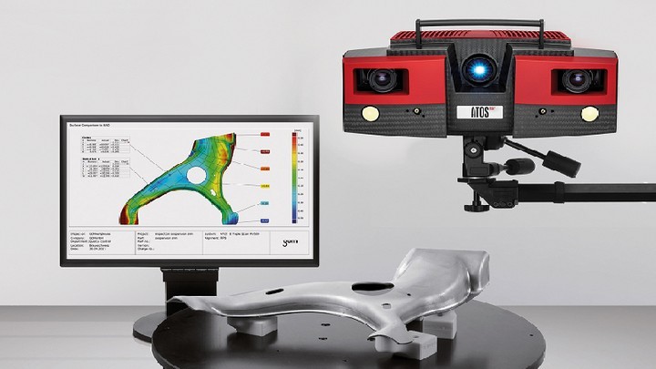
Fig. Figure 6: Scanning an ear impression with the 3Shape H600 scanner.
2. IMPRESSION SCAN
Place the impression in the 3D scanner where its shape will be scanned in just 30 seconds. The scan transfers the physical geometry of the impression to the computer as a digital file
Due to the small functional size and organic shape of the impression, earmold labs use scanners designed for this particular application. The digital file will still be a raw ear impression data format, which then needs to be edited for a specific earmould application. nine0003
3. EARGEL DESIGN
Edit the digital file using software designed specifically for editing earmolds. Use the software tools to create hollow and smooth sections of the model, cut channels and add material as needed. To print a shell for injecting soft liner material, empty the part and specify the wall thickness of the shell (usually 0 to 0.8 mm). For hearing protection with additional parts, such as decibel filters for headphones, model the shape of the filter in the shell to leave a cavity when the part is printed. nine0003
Several different software packages are available. The standard package is 3Shape.EarMouldDesigner. Although software integration will be a new process for a lab that currently uses a traditional workflow, training on how to use the software is readily available and the digital interfaces are designed to follow the steps in traditional processes intuitively and in parallel. Figure 7: Editing the file in 3Shape EarMouldDesigner audiology software. nine0003
What exactly needs to be edited in the original print?
The optimally fitting earmould rarely takes the exact shape of the original impression. Any inconsistent or rough areas of the impression are smoothed out and material is often added to increase the overall thickness and ensure a snug fit. This process serves the same purpose as adding wax layers to impressions in the traditional manufacturing process, increasing the overall volume to the final cast. Also, if the shell is to be used to inject another material, as in this example process, the mold must be hollow and small drain holes are added throughout the shell so that the polymer can escape after printing and air/silicone can escape during injection. . The injection cone is installed in a carefully chosen location to allow for easy shell injection as well as potential print support as an alternative to using supports created by PreForm. Each shell may have an identifying name and identifiers added to track and identify the left and right earmould. nine0003
Fig. 8: Editing a file in PreForm.
4. PREPARING TO PRINT
Export the file from the earmold software as an STL file and load it into the free PreForm software, which will prepare the file for printing on Formlabs 3D printers.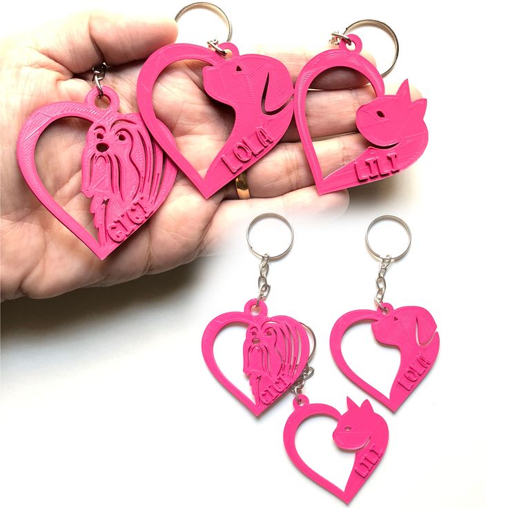 Simply select the correct orientation with the Surface Selector and create and edit supports as needed. You must ensure that the "Create Internal Supports" selection is not checked to ensure that the internal supports do not fill the hollow shell. nine0003
Orientation is the key to successful 3D printing of organic earmould shapes. With SLA printing, it is important to ensure that each printed layer is properly supported by the previously printed layer. If a layer is not bound to a support tip or a previously printed layer, it cannot be printed. This can often be the cause of the overhang and inner layer problem when an unsupported layer extends beyond the junction point.
Fig. Figure 9: Layer diagram and inner layer (shown in orange) that cannot be supported. nine0003
An unsupported location is often referred to as a "print island" because the location appears as a floating island when the part is scrolled using the layered slider in PreForm. The issue of print islands is usually resolved by creating a support below the location that works for the outer layers.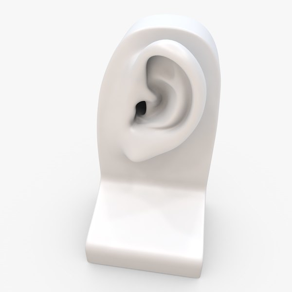 However, internal components must not be supported, so the parts must be properly oriented to avoid any internal print islands. This can be verified with the PreForm 9 layered slider0003
Fig. 10: Each of these five prints is the same, but orientation can determine print success. The four prints on the left will print without problems, but the fifth print is oriented so that the internal function creates a print island.
The Formlabs Design Guide outlines general design guidelines for orientation, but the orientation of organic forms such as the above are often quickly learned through gaining experience with printing different types of forms. nine0003
PreForm generates a support optimized for successful printing, but you can also print directly on the build platform if the part geometry allows it. The injection cone can be placed on the part in a printable location, similar to a support. This can work as long as there are no islands of print left (either on outer or inner elements) and no extensive protrusions, which PreForm identifies with shades of bright red. Also note that using the injection cone as a support limits the placement of the cone to a location that respects these geometry limitations. If there is a specific site for optimal injection, it may not match the placement for optimal support. nine0003
Fig. Figure 11: On the left is an earmould shell successfully printed with the injection cone as a support, and on the right is the same earmold shell with the injection cone in a different location supported on the supports generated by the PreForm.
5. 3D PRINT
Once the file is preformed in PreForm, load the Form 2 with a standard cartridge with clear resin and Formlabs standard resins which will produce high quality prints as the uncured resin has a relatively low viscosity for easy cleaning internal cavities, and the final print material has optimal mechanical properties for sheath removal after silicone injection. A complete build of the platform will take two to five hours to print at a recommended layer thickness of 50 microns, but print times will of course vary based on mold geometry and shell styles.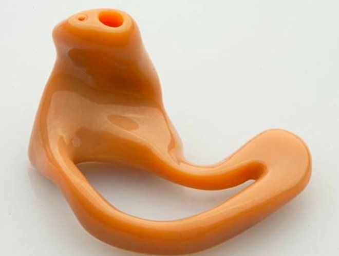 nine0003
Fig. Figure 12: Complete assembly of earmould shell platform printed in 5 hours at 50 micron layers.
6. CLEANING THE 3D PRINTED PARTS
Visually inspect the printed parts to make sure there are no malfunctions, then dip them in an isopropyl alcohol (IPA) bath and flush the inside of the shell with a syringe. Repeat the flushing process, shaking the print in the IPA until it looks like all of the uncured polymer outside of each shell. Depending on the shape of the printed envelope and the location/size of the drain holes, an ultrasonic IPA bath may be required to thoroughly rinse any uncured resin from the inside of the print. nine0003
Any resin remaining on the inner surface of the shell may result in inaccurate shell thickness after the print is cured, or sticky residue if the prints are not fully cured, degrading the quality of the final silicone mold. To ensure that residual liquid is removed, compressed air can be blown out of the printed envelopes after rinsing.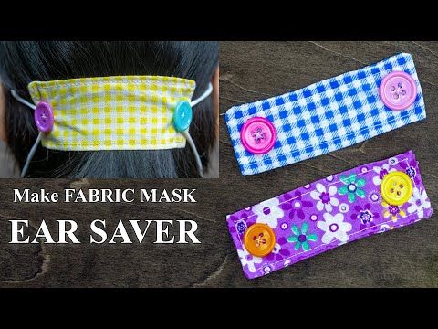
Fig. 13: Imprint injection with IPA to remove any uncured polymer.
7. AFTER TREATMENT OF PRINTED PARTS
After the casings have been washed and dried sufficiently, post-process the parts for 30-40 minutes. Although post-treatment is not required with Formlabs Standard Resin, it is useful in this process to ensure that any residual resin that may have entered the print is completely removed and that the injection of silicone is uniform. Post-processing can also increase the brittleness of the printed material, which is beneficial in this application for skin removal later in the process. Due to the organic shape of the ear tips, post-processing must be done with full rotation of the parts to ensure that all areas of the shell are completely finished. Formlabs Form Cure automatically rotates parts using the turntable and functions properly for this application. For static post-processing solutions, you may need to flip or rotate the part midway through the process to achieve uniform post-processing.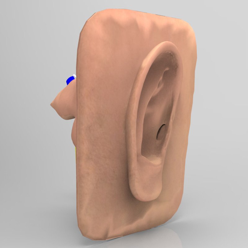 nine0003
8. PRINTED CASING INJECTION
The 3D printed casings are now ready for silicone injection. Coat the inside of each shell with a remover spray designed to prevent the silicone from sticking to the shell material. Inject a few drops into the shell and swirl the shell, ensuring that all internal surfaces are covered. This step is not absolutely necessary, but may make it easier to uninstall the shell
Load the material cartridge into the spray gun and attach a material specific mixing tip to the cartridge. Mixing tips are required to ensure proper mixing of the two-component silicone prior to injection. Slowly inject the silicone into each shell ensuring that all gaps and voids are filled.
Fig. 15: Injection of Dreve's BioPor® AB 40 Shore silicone into the printed casing.
Injectable silicone is in a sealed cartridge and most air bubbles must escape from the shell during injection, but micro air bubbles, which are almost invisible to the human eye, can enter the mold.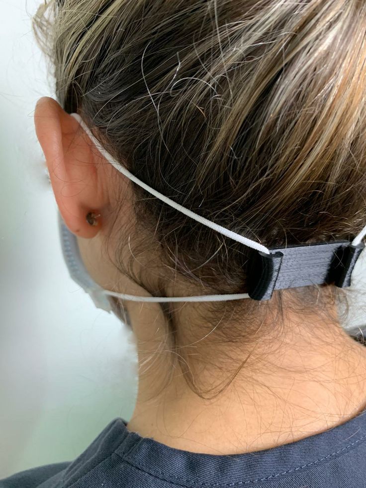 To achieve the highest quality and most resilient products, remove this air by placing the casting immediately after injection in a pressure vessel for 30 minutes at 40°C and 4 bar. Hobbyist digesters typically cannot safely reach this pressure, so industrial equipment such as Dreve Polymax pressure polymerizers must be used. This is the same equipment and process step that is commonly used for the traditional production method of indirect injection molding of the silicone earmould. The temperature and pressure will force any trapped bubbles out of the silicone. nine0003
If parts have supports, it may be helpful to remove the supports prior to injection using the cutters that are part of the Form 2 Finishing Kit. This can make it easier to visualize how the printed envelope is being filled and any air bubbles that form. However, it may also be easier to hold the injection seal with supports. Support removal time is largely a matter of personal preference and how well injection is performed for a given shell geometry.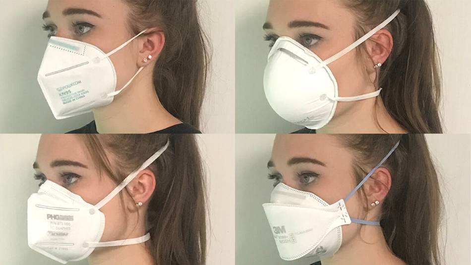 nine0003
Fig. 16: Removing the support with nippers
What is injection material?
Soft eartips are usually made from biocompatible, audiology-specific silicone, although other materials may be used. The silicone injections come in two-component cartridges that are mixed while the silicone is pushed through when injected. There are different types of silicones available on the market, and the main differences are hardness, color, and opacity. nine0003
The hardness of silicone is measured in terms of Shore hardness. Standard Shore hardness for soft, customized earmoulds ranges from 20 to 70 Shore A. The lower the number, the softer the material, and the letter represents the test scale using a durometer (A for softer materials, D for harder materials) .
9. SHELL CRACKING
Once the silicone has completely cured, the sheath is ready to be removed. Shell cracking can be done using a variety of methods and is usually done by squeezing the casting in a vise or using pliers.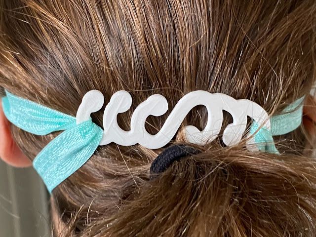 Remove pieces by hand or with tweezers. Repeat these two steps until all parts are removed. nine0003
Note: This step must be done very carefully to ensure that the soft silicone is not damaged during the removal of the shell, as pieces of the shell may penetrate or break the silicone mold. Using the accumulated experience of the laboratory, they develop methods for the most effective removal of the shell. As expected, the different forms of liners represent different approaches to shell removal and cracking techniques. Silicone hearing protectors using decibel filters or internal channels take a unique approach to shell removal as the internal printed components must be carefully removed from the silicone mold. nine0003
If the print case has been thoroughly cleaned and processed and the silicone plate is still tacky, leave the print for 8-12 hours to ensure that all silicone has hardened before removing it from the print case. This is not normally required in a thorough cleaning mode, but may be necessary if the sheath geometry is such that uncured polymer is extremely difficult to remove from the sheath.
Fig. 17: Cracking and removal of the shell from the earmould. nine0003
10. FINISHING THE INSERT
After removing the casing, inspect the liner for any major defects that cannot be repaired after finishing. If all visual indications are satisfactory, the liner is ready for finishing. Use nippers to carefully cut out the small bits of silicone that stick out through the air holes during injection and the remaining silicone piece from the injection cone from the liner. Then, as applicable for optimum surface finish, sand and polish until all surfaces are smooth. nine0003
A Dremel Bench Lathe and/or Flexible Shaft is typically used for mold polishing and variable speed is needed for optimum control. Choose drills, bits and cutters that are specific to finishing soft, sticky material like silicone; medium grit sandpaper and sanding caps perform well, while large cutters tend to just move the silicone without removing the material.
Recommended finishing tools can usually be obtained from audiology material manufacturers and suppliers.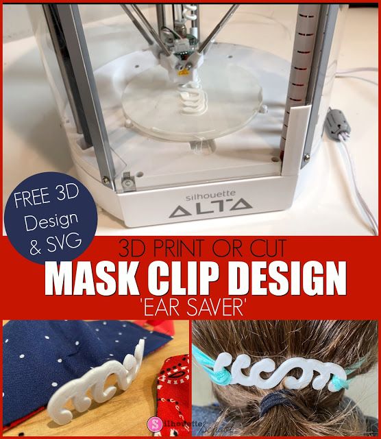 The Listening Stack use all of their finishing tools from US
Supplier, Warner Tech-Care Products, LLC. Due to the viscosity of silicone, the material is relatively difficult to machine and an error can easily lead to breakage during the process, so optimal tools are essential. Silicone also traps dirt and dust easily, so the less finishing required, the better. Due to the high quality casting, very little finishing is required. nine0003
Fig. Figure 18: Finishing the silicone earmould using medium grit sandpaper on a Dremel Flex Roller.
Fig. Figure 19: Coating silicone with Dreve's Lack B eco-friendly top coat.
Once mold is smooth, top coat with silicone sealant for long lasting cleanliness and wear protection; There are many different types of lacquers available for a variety of purposes and surface finishes. The lacquer can be brushed, dipped or sprayed with an automatic coater and serves to provide an easy to clean, durable, biocompatible skin contact surface. Depending on the type of coating, the finished mold may cure under ambient conditions or may require additional post-processing. nine0003
Fig. 20: Checking the fit of the ear tips.
11. FIT CHECK
Inspect the final product for defects and test the dome on the patient for fit and hearing protection properties. Assemble the earmold with other components such as tubing or electronics, if any. After checking the assembly, inspection and fit, the patient leaves with their new, comfortable ear tips.
Conclusion
3D printed custom earmoulds have revolutionized the field of audiology, but the availability of the technology has been largely limited to a few large laboratories. Smaller labs and factories either continued to use the traditional manufacturing approach or outsourced their custom liners to these larger players. nine0003
The integration of the Form 2 into the manufacturing process has allowed small businesses like The Listening Stack to take advantage of the digital workflow and 3D printing of custom earmolds. Most importantly, by using an automated digital assembly workflow, The Listening stack cut manufacturing costs by 40 percent compared to outsourcing and more than halved rework, with no compromise on quality and at a very low investment.
Transitioning to a digital workflow requires training and some upfront costs, but after a full transition, Justin believes Form 2 printing has reduced rework from 20% to less than 8%
| FEATURES | SPECIFICATION FORM 2 |
| Assembly platform size | 57 X 57 X 69 inches 3 |
| Inserts / shells for each platform | 20 — 30 |
| Print time for complete assembly | 2 to 6 hours |
| Printing material for one full spiral casing | 3.3 ml ($0.49) |
21: Complete assembly platform with various printing styles for silicone injection.
The Form 2's small size and affordable price offer advantages for large-scale production laboratories as well.