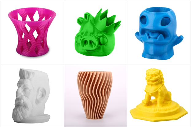
3D print round objects
4 Ways How to Fix 3D Printed Circles That Aren’t Perfectly Round – 3D Printerly
If you have tried printing a circle on your 3D printer and it keeps coming out as an oval shape, you definitely should get this issue fixed. Finding the solution can be quite troublesome, so I decided to write an article that is easy to follow that should help solve this problem.
The best way to fix 3D printed circles that are not round is to tighten the belts of your X & Y axis. Loose belts cause a slack in the movement of your print head, resulting in poor dimensional accuracy and that oval-shaped circle.
This article will describe the causes of 3D printed circles not being round, and give info on how to fix it so you can 3D print round holes and circles consistently.
What Causes 3D Printed Circles to Not be Round?
Printing circles that are not perfectly round is a common problem and usually occurs when users don’t pay attention to minor settings, especially in calibrating the axes.
This problem not only causes an issue while printing round shapes but also damages the holes that you want to print for different purposes such as for screws or to hang the print.
A user may face this problem often, but the best thing about this 3D printing problem is that it can be eliminated and fixed out just by the help of some simple techniques.
Finding the actual cause can make your fixing process easy as you will not have to check the whole printer’s hardware or to adjust different 3D printing settings.
- X-axis and Y-axis Belts are not tightened
- Pulley is slipping on the motor shaft
- Motors are receiving too little or too high current
- Incorrect number of steps/mm in extruder motor
How to Fix 3D Printed Circles That Aren’t Round?
The problem of 3D printed circles that aren’t round usually occurs due to the improper calibration of the X and Y-axis.
If the dimensions are not calibrated accurately, there are huge chances that you will face this problem as the circles may come in the shape of an oval or near to a square, etc.
Fixing the 3D printer is necessary to get 3D printing perfect circles because this issue may ruin your whole project wasting your time and filament as well.
It is important to find out the actual cause behind the issue because it is the only way to do perfect 3D printer circle calibration and resolve the issue of improper circles.
Let’s talk about some of the most efficient and easy to implement methods that will not only help you to fix the 3D printing holes not round issue but may prevent other problems from occurring as well.
1. Tighten the X-axis and Y-axis Belts
If your Ender 3 circles are not round or no matter what printer you have, the first thing you should check if you face this problem is the X axis and Y axis belts.
The filament will smudge or will be misplaced if these belts are not tightening perfectly. This may cause your circles to not perfectly round and give poor results while printing holes in your print.
- Make sure that the x-axis and y-axis are calibrated accurately, usually, the problem only occurs in the belt on the x-axis.
- If the belts are not tightened properly, loose the screws on the axes and adjust the belts by pushing the x-axis motor outside.
- It is recommended to adjust the belt before you start printing as it may waste your time if you fall into such an issue while printing.
2. Tighten the Pulley Against the Motor Shaft
This problem may also occur if your pulley is not tightened against the motor shaft nicely as the pulley may begin to slip when the printing process starts. This is the part that your stepper motor & belt use to transfer movement.
If the pulley is slipping, it can disturb the print by causing a misalignment problem.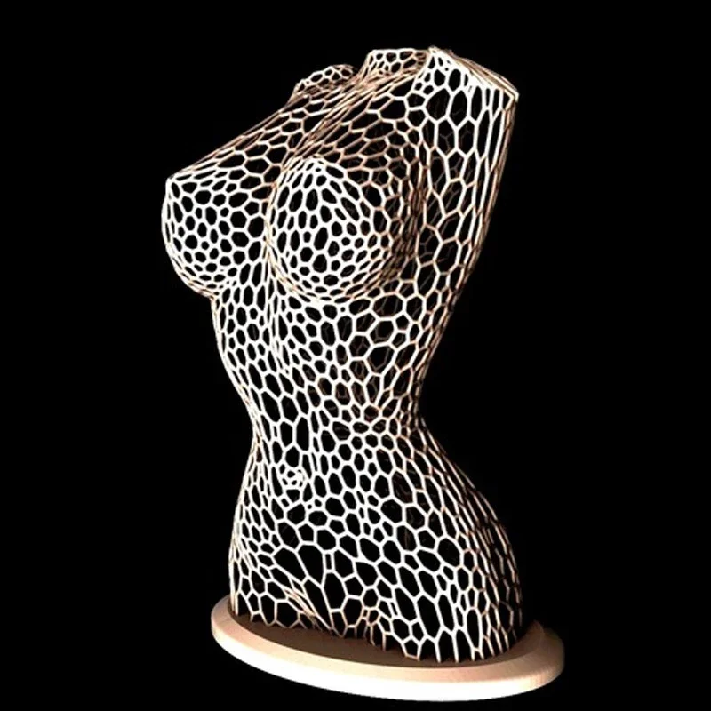 The filament can start to extrude incorrectly and in the wrong places.
- Make sure that the pulley is aligned and tightened and against the motor properly
- Do this by aligning the grub screw with the flat side of the motor shaft (don’t tighten the grub screws too tightly).
- Make sure that the X axis and Y axis belts are not so tight or loose as this can also cause the pulleys to slip while printing.
- If you are still facing the problem even after tightening the pulley perfectly, try printing at a slower speed as it can help in many scenarios.
3. Provide the Perfect Voltage to the Motor
Improper voltage can also be a cause of this problem as the motor will not work properly if it is receiving too little current while printing.
You may see at most times, your print is smooth and perfect and the next moment you may notice that the amount of material extruded decreases randomly drops off or there are lines in your prints that are ruining the circles or holes.
Th4D Studio done a great video which shows you how to adjust your PSU voltage and stepper VREF voltages. Do keep in mind, this can be dangerous so you want to know what you’re doing beforehand.
If the motor receives low current, it may not keep pace with the printing material and the slow movement of the stepper motor will provide space for the filament to drop off in the wrong place.
- Make sure that the stepper motor is receiving the required current because if the current is too little the stepper motor will not drive properly.
- If you hear a clicking sound when the motor stalled or the motor is vibrating it means that the motor is not receiving enough current.
- The vibration of the stepper motor disturbs the printing quality but when the current and connections will be in order, the motor will start working smoothly instead of vibrating.

This is can also be known as inconsistent extrusion which I wrote an article about – 5 Ways How to Fix Inconsistent Extrusion in 3D Prints which many people have found helpful.
4. Calibrate Number of Steps/mm on Your Extruder
This can also be a problem that your motors may not be stepping the correct number of steps/mm. With providing enough current you should pay attention to this part of the 3D printing as well.
There are a few ways to check your current number of steps per millimeter. It used to be where you had to send an M503 G-Code command to your 3D printer, to look for values on your display, then finding the echo: M92 line.
At the end of that line you’d find a value following ‘E’ such as E100.5 or E93, and this would indicate the number of steps per millimeter.
Although many 3D printer extruders have default steps, you may have troubleshooting to do if it is far off. One issue is bad spring tension, where your 3D printer isn’t gripping the filament tight enough to extrude it through the pathing.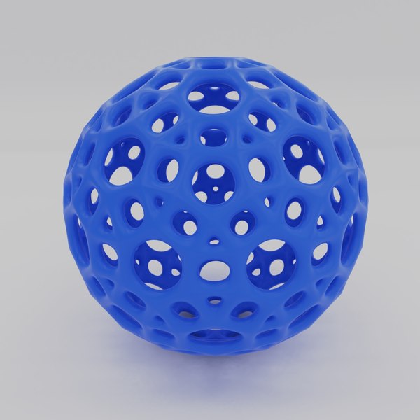
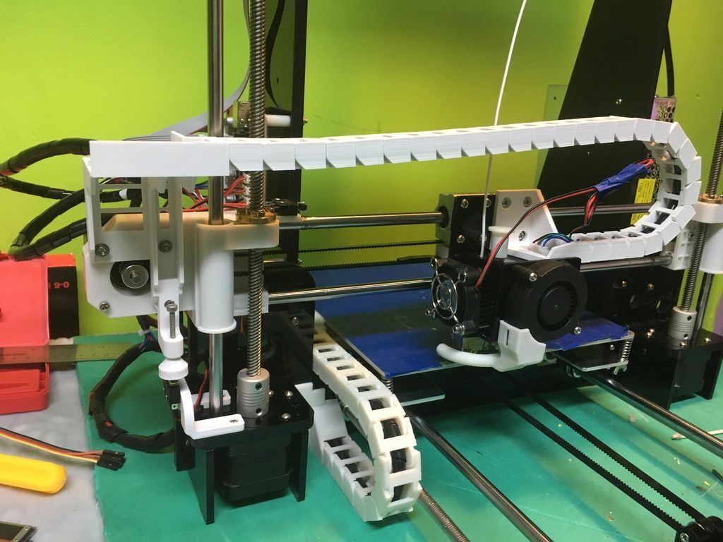
Nowadays, as seen in the picture above, you can usually find and edit your number of steps per millimeter directly within your 3D printer. I got the TFT 3.0 Touchscreen by BIGTREETECH on Amazon which is a great addition to your 3D printer.
You can also go into your 3D printer menu and under an option like ‘Control’ > ‘Motion > ‘E-Steps/mm’.
In order to find the accurate number of steps per mm for your 3D printer and extruder, there is a formula that you can follow. It does require a good set of calipers to measure accurately.
The stainless-steel Kynup Digital Calipers is one of the highest rated calipers on Amazon, and for good reason. They are very accurate, up to an accuracy of 0.01mm and very user-friendly.
- What you want to do is mark 100mm of filament from the outer-side of your extruder where the filament first enters.
- Then extrude 100mm of filament through either a G-Code command or directly through your 3D printer.
- Measure the actual value that was extruded, so if you have 15mm leftover, then you extruded 85mm rather than the expected 100mm.
- Multiply your current steps/mm value with the length you expected to extrude, then divide that value by the actual extruded value.
- If your current steps/mm was 100, then you would do 100 (current steps) * 100 (expected extruded amount) / 85 = 117.64 (new steps/mm).
- Enter this new value & repeat the process again until the actual extruded amount matches the expected extruded amount (100mm).
5 Ways To 3D Print Near Perfect Circles Every Time – 3D Printing Realms
When I started 3D printing, I had trouble getting circles and other round objects to print correctly. I found a few different ways to get near perfect circles every time.
One note, you will never get perfect circles from a 3D printer.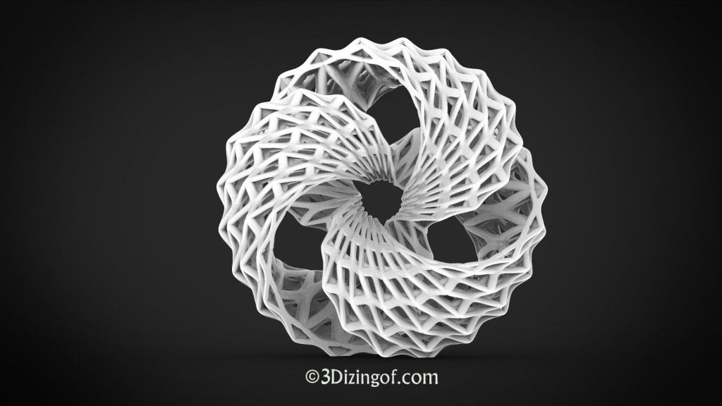 3D printers use stepper motors that move print heads and build plates in fixed increments. The smaller the steps, the closer the printer will come to perfect circles.
The same holds true for LCD SLA printers, but for different reasons. These printers expose resin to UV light using an LCD screen. While the pixel size can be extremely small, a series of square pixels will never be perfectly round. But they can be really close.
Table of Contents
Check For Design Issues
Designing round object is very difficult. In every CAD program, all circles are exported to STL as a polygon with a lot of sides. As the number of sides increases, the object appears more like a circle.
Expand this to 3D models. Round objects become a series of polygons. The more polygons there are, the closer to perfectly round the object becomes. But each polygon takes up some memory and higher polygons result in larger file sizes.
If you are the creator of the design, you can adjust the mesh resolution of the object when converting it into an STL file for 3D printing.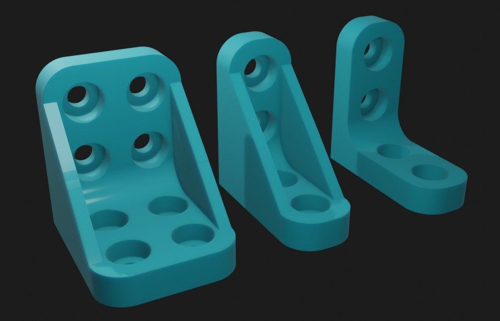 Autodesk has a setting, FACETRES, that can be adjusted to increase the resolution.
The 3D Printing Professor made a great video on how to make Blender models more smooth.
If the model was something you downloaded, you can import it into Blender to improve its roundness. Here are a few steps if you are familiar enough with Blender to make an attempt. Otherwise, you can approach the original designer and request a higher resolution model.
Those are the way the model could be the problem. If the model appears nearly perfectly round in the slicer and other users have shown off their prints that came out looking right, it may be the printer that needs adjusting.
Tighten Your X and Y Belts
Printers like the popular Ender 3 and the ANET A8 use belts to move the print head along the x-axis and the build plate back and forth along the y-axis.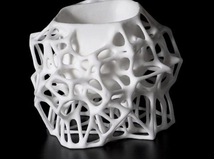
If circles are printing ovaloid or you are getting layer shifting, that is a good indication that you need to tighten your belts.
Over time, belts can become loose as they stretch from the pulling back and forth during printing.
If either of the belts is loose, circles may be slightly ovaloid. The slack in a loose belt will cause the print head or build plate to move less than intended.
Loose belts can also result in layer shifting. As the stepper motor spins, a loose belt could fail to grip. This resulting in printing a layer in a different spot then intended, resulting in misaligned layers.
Some printers have belt tensioners built in. In those cases, simply increase the tension on the belt until the belt give a slight twang when plucked.
Without a tensioner, you will need to manually tighten the belt. You have to disconnect one of the ends of the belt from where it connects to the hotend or the build plate. Pull the belt tight and reattach.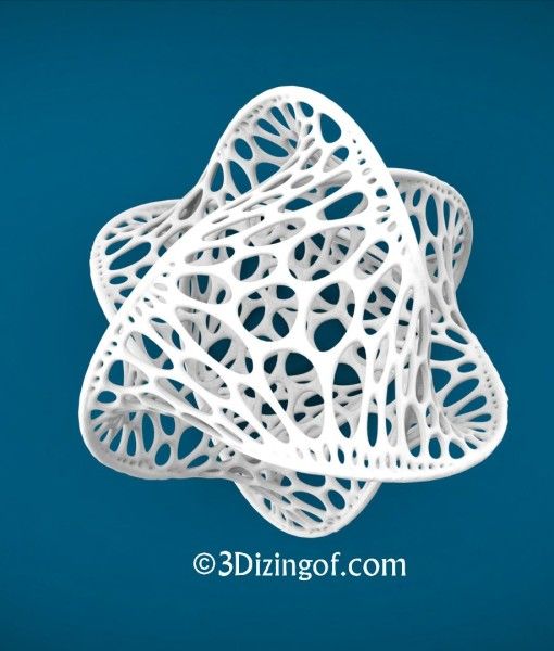
Do not over tighten. If the belt is too tight, the excess tension can cause the belt to snap.
Fix The Pulley On The Stepper Motor
If the belts are tight but the pulley is loose, you can get a similar ovaloid shape when you attempt to print a circle or layer shifts. If the pulley is loose, it can slip on the shaft from the stepper motor when it is supposed to turn.
You can check if one of the stepper motor pulleys is loose by turning it slightly. You should get some resistance from the stepper shaft. If the pulley wiggles a little bit before locking on to the shaft, the pulley is loose.
The stepper motor pulley is attached to the stepper motor with a small hex screw. The hex screw goes through the pulley and grips the flat side of the stepper motor shaft.
- Loosen the belt to get access to the pulley
- Make sure the grub screw is properly aligned with the flat side of the shaft
- Gently tighten the screw
- Replace and re-tension the belt
Once the loose pulley has been fixed, retry your print to verify that it has been fixed.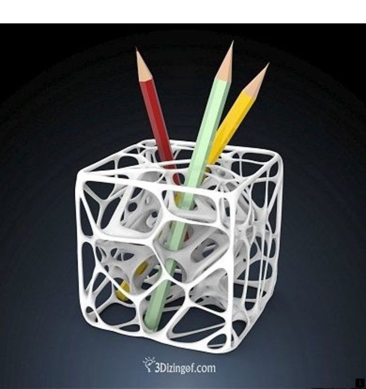
Calibrate Your Stepper Motors
Your stepper motors, as their name implies, move in steps. Each step moves the print head or build plate a certain distance.
The printer controls the stepper motors by signalling how many steps to take. In order to move the correct distance, the printer needs to know how far the print head or build plate move with each step.
You can find the current set steps-per-mm in the configuration settings of your printer. Alternatively, you can send a GCODE command, M501 or M503, to read the values stored in the printer memory known as EEPROM. These can be sent through most slicers or using a Raspberry Pi. If you want to set up a Raspberry Pi to control you printer, I have instructions here.
Using the GCODE, you will get a bunch of values from EEPROM. The line you are looking for should look like
echo: M92 X80.00 Y80.00 Z400.00 E93.00
The values after the M92 are the current stepper values.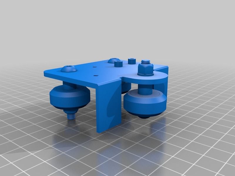 Each value identifies the axis then the number of steps per mm. E identifies the extruder motor steps setting.
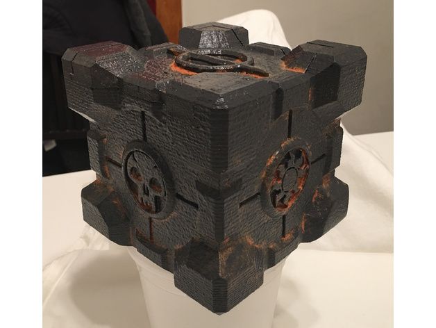
- Print this calibration cube from Thingiverse
- Measure the length of all sides of the cube using calipers or a ruler
- You can get an affordable set of good calipers on Amazon
- Each side should measure exactly 20 mm
- Calculate the new steps-per-mm
- New Steps = (20 / measured length) * Old Steps
The GCODE for setting the new steps is different for each axis. If the steps need to be set to 80, use the following codes depending on the axis. Replace 80 with the steps-per-mm you calculated.
| X-Axis | M92 X80 |
| Y-Axis | M92 Y80 |
| Z-Axis | M92 Z80 |
You can set all 3 settings at once using M92 X80 Y80 Z80.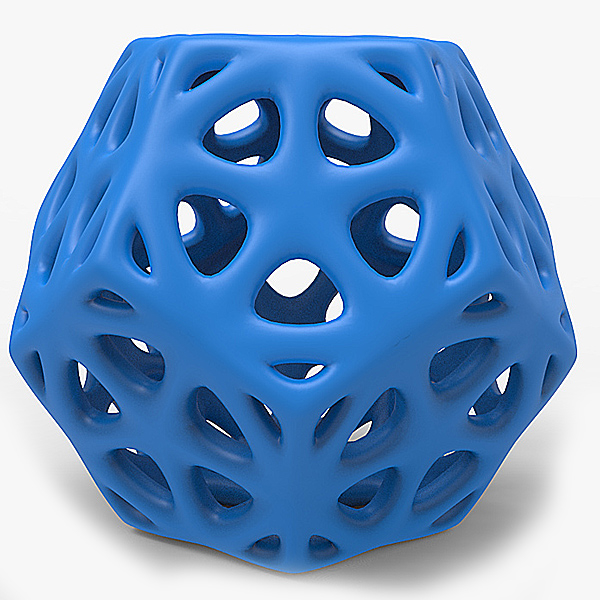
After entering the GCODE, you have to use M500 to save the new setting. If you don’t save the settings, when the power is turned off, the settings will be reset.
Check That The Motors Have The Right Voltage
If the voltage is not set high enough your stepper motors might not have enough power to pull the belts on your 3D printer. Checking and modifying the voltage on your printer can be very dangerous. Do not mess with your system power unless you are confident that you know what you are doing and take proper precautions.
To check the voltage on you system, you will need a voltage meter or multimeter. This affordable multimeter from Amazon is a great choice if you need one.
You will also need a ceramic tipped screwdriver. The ceramic type ensures that if you accidentally touch the control board you won’t short it out. You can grab this set of ceramic tipped screwdrivers from Amazon.
Th4D Studio created this video to show you what you look for and what to set to properly check and set your voltage levels.
<iframe src="https://www.youtube.com/embed/pJRYXKRAUN4" title="YouTube video player" frameborder="0" allow="accelerometer; autoplay; clipboard-write; encrypted-media; gyroscope; picture-in-picture" allowfullscreen></iframe>
Conclusion
It can be frustrating when you are trying to print something round or circular and the print comes out wrong. But with just a few steps, you can get back to printing near perfect circles in no time.
short tips for the transition from a CAD model to a printed object / Sudo Null IT News
was withdrawn from publication due to a technical error. Please be understanding. Thank you!
Whether it's just a hobby or a source of income, 3D printing is always based on product design. Those accustomed to traditional technologies will have to rethink the entire approach to product design and manufacture. nine0008
When the project is ready, a number of additional operations are performed: setting the orientation of the model and other parameters that ensure the proper printing process.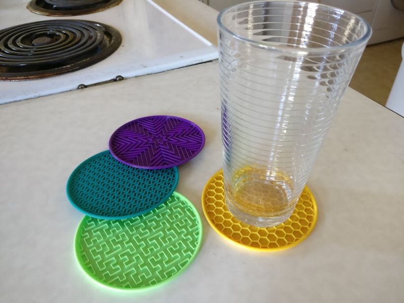 In addition, it is necessary to take into account the fact that most 3D printers allow you to choose the degree of filling the model with cellular structures. The correct choice of this parameter provides protection of the object from deformation and destruction during the printing process, as well as significant savings in material and reduction in production time.
Finally, the last factor influencing the success or failure of the 3D printing process is the strength of the connection between the model and the table. If the workpiece is separated from the table during printing, then all the work will go down the drain.
Here, we'll walk you through the 3D printing process and give you some simple tips on how to use additive manufacturing in the design phase. In addition, we will dwell on the methods of preparing a finished project for printing, and also consider ways to securely fasten the workpiece to the table. nine0002
These guidelines apply primarily to Fused Deposition Printers (FDM) printers, but may apply to other types of printers as well.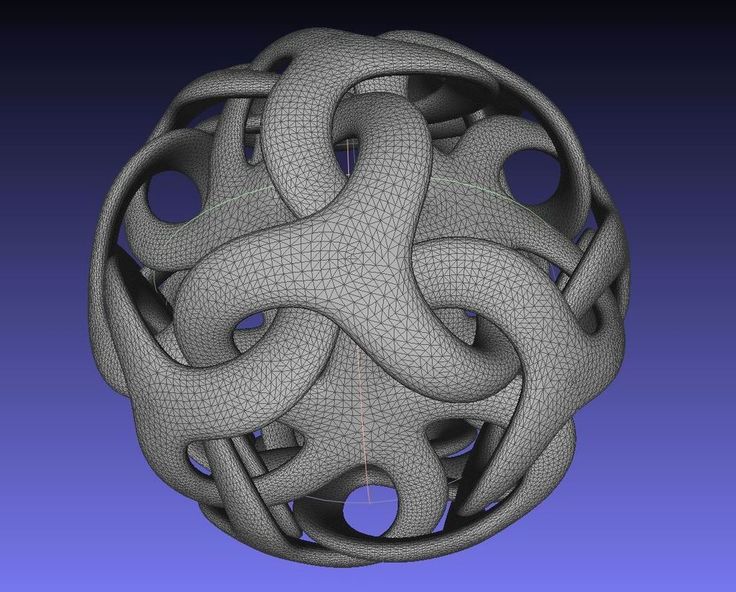 The process of obtaining a finished part by 3D printing is basically the same regardless of the method used.
Designing an object
Any 3D printing starts with construction. If you are developing a product yourself, then you need to build a 3D model of it in a computer-aided design (CAD) system to turn the designer's idea into reality. In this case, the object can be both very simple and very complex. However, too thin and too small models should be avoided. nine0008
3D-CAD from Siemens from this article for 49900r (90% discount), the promotion is valid until March 20, 2020. Read more>>
Saving the file in a special format for printing
To print an object, its model must be saved in a special file format - for example, STL, which has become the de facto standard in the world of 3D printing. In this format, model surfaces are represented as a grid of triangles. Simple surfaces are broken down into a small number of triangles.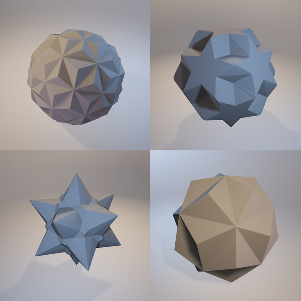 The more complex the surface, the more triangles you will need. Today, other formats are used in 3D printing, in particular, the 3MF format developed by Microsoft. But the most common is still STL. nine0008
CAD systems make it very easy to save the model in the desired format: just click the Save As command. To improve print quality, it is desirable to set a number of settings for saving to the STL format - for example, the tolerance during transformation and the angle of the plane. The lower the conversion factor and the better the angle, the smoother the printed part will be.
Opening the file in the slicer program
Most, if not all, 3D printers come with their own slicer software. The slicer loads the STL file created in the CAD system and cuts it into layers, and then creates a control program for the printer. nine0008
Place the model correctly in the print space
After entering the print settings, the model (or several models) needs to be placed on the printer table. You can print many objects on one table at once. At the same time, compared to printing a single object, the time slightly increases, but in general it still turns out to be less. Here are some tips for choosing the right model orientation.
Set parameters
In the slicer program, the user sets parameters such as print speed, material consumption, nozzle and desktop temperatures. Most slicers have simple settings for beginners. In this case, most often there are also advanced settings so that experienced professionals can achieve optimal results. Advanced settings include percentage infill, amount of backing material, and type of backing or raft (this is a small, thin base that keeps the printed part stable. The backing is removed when it's finished). The number of options is truly endless. Specific settings vary depending on the brand of printer. It's easy enough to set them up. nine0008
Sending the control program to the printer
After setting the print settings, the placement of future objects on the table, their orientation and quality, it's time to finally start the printer. It is enough to press the Print button and find something to do while the production is in progress. Depending on the complexity of the design, the process takes from several minutes to several hours.
Finishing
Finishing includes removing the printed part from the table, as well as removing the support material by melting, mechanical separation or dissolution (depending on the design of the printer). The part may require some light sanding or polishing, but overall a properly printed object looks good from the start. Other types of finishing are placing plastic parts in a container with acetone to smooth out surface roughness, gluing (if the dimensions of the structure exceed the dimensions of the 3D printer or individual elements of the object must have different orientations), drilling holes and painting. nine0008
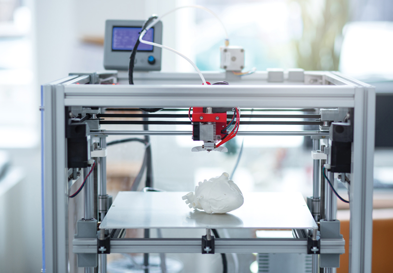
3D printing process
3D printer design considerations
Eliminate sharp corners
If the direction of the surfaces changes abruptly (for example, a vertical wall intersects with a horizontal overlap), then such a model is difficult to print. The printer will build excessive inner surfaces, wasting too much material. There are two easy ways to prevent this: add chamfers to smooth out where the surfaces meet, or round the corners so the printer gradually builds a vertical surface. In addition, rounding will increase strength, since destruction most often occurs at sharp corners. nine0008
Elimination of thin walls and small geometries
Layer by layer fusing technology consists in supplying hot plastic through a nozzle with the formation of a printed object layer by layer. The thickness of the extruded plastic layer cannot be made smaller than a certain limit, depending on the diameter of the nozzle and the speed of the print head. Excessively thin-walled details are difficult to print - often the result is a chaotic weave of fibers. If the part can be printed, it is very fragile and breaks easily. nine0008
Too thick walls - also bad
On the other hand, if the walls are too thick, they become brittle and crack easily. This is especially important when printing from materials other than resins, as excess thickness during the manufacturing process leads to internal stresses in the part. Even when printing from plastics, material is wasted on walls that are too thick and time is wasted.
Removing large overhangs
3D printers allow you to create amazing shapes and surfaces, but they are not capable of printing directly in the air. If there is a void in the part with material above it, additional support material must be used. Most slicers add material automatically, but require you to specify the orientation and volume of the support structure. Printers with a single nozzle create an array of thin columns, which then have to be broken off. The result is an uneven surface. Therefore, it is recommended to avoid large overhanging elements whenever possible in order to reduce the need for support material. nine0008
If such an element is unavoidable, you can try to flip the object. Most printers are capable of printing overhanging elements with an angle of about 45 degrees. At a certain height, the edge of such an element may sag somewhat. The actual capabilities of a particular printer are determined by trial and error.
Holes shrink
Remember that the part is made of heated plastic. As it cools, it inevitably shrinks. Therefore, holes and other critical structural elements have to be made larger so that after shrinkage their size is as close as possible to the required one. nine0008
However, if you need to make a tight tolerance hole, it is better to print it with a smaller diameter and then ream it with a suitable tool. This is especially true for holes whose axis is parallel to the printer table.
Increasing the footprint
If the area of contact between the object and the base is small, the part may separate from the table during printing. To prevent this from happening, wide bases are added to the model legs, which are installed on the printer table.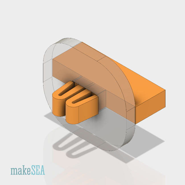 In general, the closer to the table, the more material must be added to the support. There are other ways to securely fasten the part to the table, which we will discuss a little later. nine0008
Special moves
The right approach to design makes printing easier. In addition, there are special post-processing techniques that are important to be aware of.
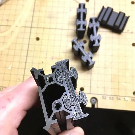
Place round surfaces vertically
The model should be oriented so that the minimum amount of support material is used. Ideally, it should rest on the table with a large flat edge. In addition, circular geometry must be placed so that the circular faces are vertical. If we look at the printer table from above, we should see a round silhouette of the object. In this case, the part comes out as symmetrical as possible with the formation of a solid round structure. nine0008
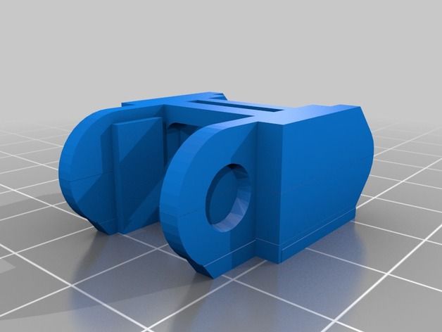
Place voids and holes vertically
If there are voids in the model (for example, it is a rectangular pipe), it is desirable to place such voids vertically in order to reduce the volume of the support material.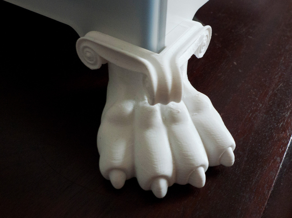 If you print the pipe in a horizontal position, you will have to provide support for the entire interior. If you put the pipe on the end, then no support is required at all.
The same is true for holes: to get a hole with a straight axis, it is best to print it vertically - in the form of a stack of rings, which avoids warping or deforming a round hole into an oval one. nine0008
Set print quality settings
Proper selection of print parameters, such as STL conversion tolerance and slicer software settings, allows parts to be produced with a surface quality that matches that of cutting. However, this entails an increase in print time. When choosing quality parameters, one should proceed from the purpose of the object: is it a finished product or a prototype? Will the part be visible or hidden? nine0002 The quality parameters also affect the shape of the holes in the part. In CAD files, holes are represented as a set of straight lines at an angle to each other.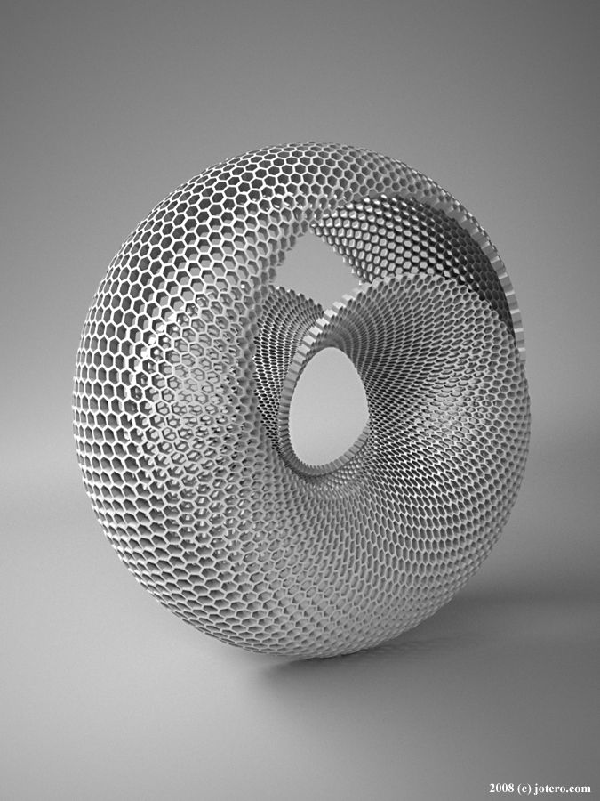 The higher the quality of the model in the saved STL file, the less the circle looks like a polygon.
Reducing the layer thickness
To obtain the best quality, especially when using layer-by-layer deposition technology, it is necessary to reduce the thickness of the layers. It does increase the print time, but the end result is worth it! nine0008
Optimizing the filling with honeycomb structures
In terms of strength, objects do not have to be solid. Similar to a honeycomb, printers can create a honeycomb infill that balances strength and saves expensive polymer material. However, if the printed part serves as a prototype for strength testing, and the serial product will be manufactured by traditional methods, and also if the part is subjected to certain types of mechanical stresses and pressures, a solid design will be preferable. nine0008
Choosing a material
The success of printing largely depends on the correct choice of material. Materials have different properties. For example, the melting point of thermoplastic polyurethane (TPU) and polylactic acid (PLA) is lower than that of acrylonitrile butadiene styrene (ABS). In addition, the material is taken into account when choosing the type of support structures. For an object made of polylactic acid, supporting elements can be made from the same polylactic acid, since it will be quite easy to separate them from the finished part. If the part is printed from ABS plastic, then the support elements must be made from a different material, and it is better not to use such elements at all in thermoplastic polyurethane parts. nine0008
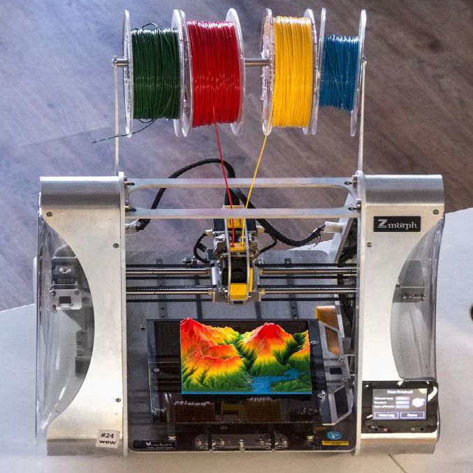
Cellular filling
A solid body is not always the best choice for 3D printing. Printing solid parts has its advantages, but the internal honeycomb structure saves both expensive material and time.
Creating objects with a specified degree of filling with honeycomb structures is a unique opportunity for 3D printing.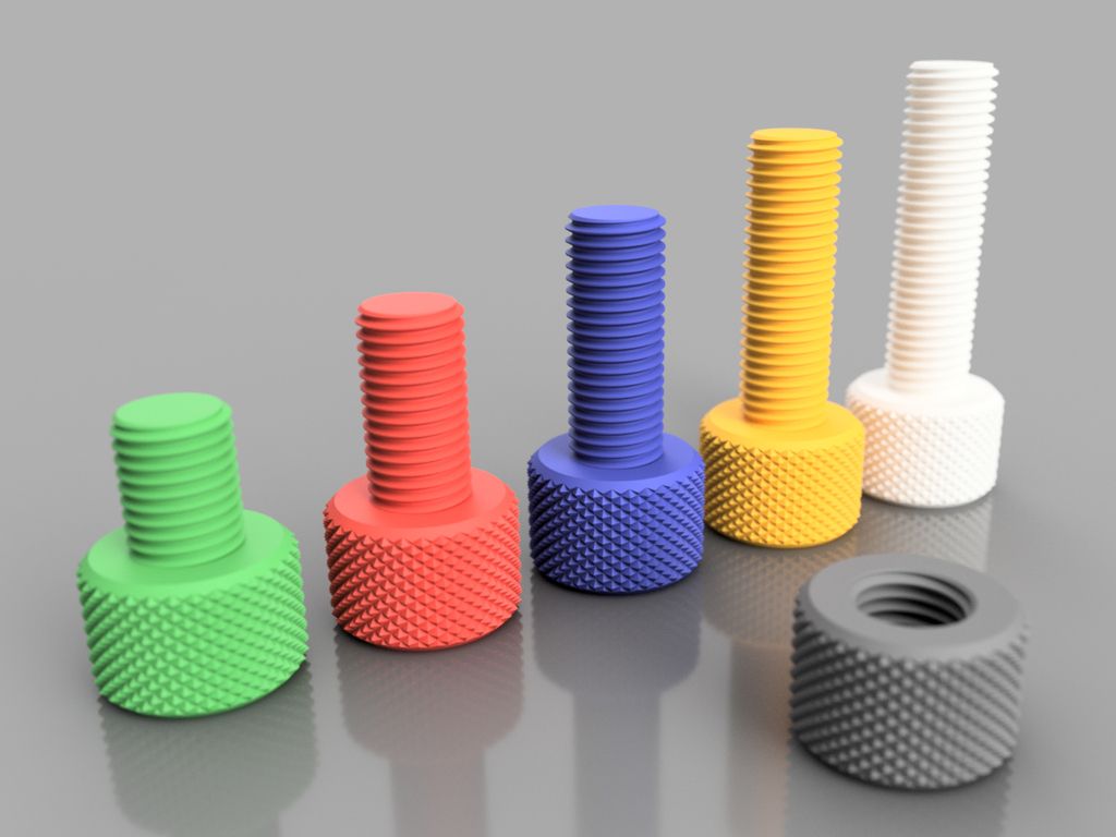 Moreover, it is not required to design such a structure: this is done by the slicer program. As a rule, it is enough to set only the percentage of filling (the closer it is to 100, the more solid the object will turn out) and select the type of cells, if the printer has such an opportunity. nine0008
In addition to saving time and material, the internal honeycomb structure has many other advantages.
Cellular filling prevents warpage
Printing large objects as a single piece introduces a danger of warpage. By reducing the infill percentage, the air during printing passes through the part, providing more uniform cooling and eliminating warping.
Cellular filling does not lead to loss of strength
Printing cells instead of solid material does not reduce the strength of the part. In many cases, a honeycomb part is strong enough for the chosen application, but lighter and less material intensive. nine0008
The function determines the choice of cell geometry
Most slicers support a wide variety of cell geometries. The optimal option is determined by the functional purpose of the object. Standard box padding simplifies printing, while hexagonal and triangular boxes add strength. Wave fill allows the object to bend or twist.
How to choose the right filling percentage?
In general, the strength of an object increases as the percentage of infill increases. Most printers have a default infill percentage of 20, which is optimal in some cases but too high or too low in others. Consider mechanical stresses in the printed object and increase the percentage of infill in areas where greater strength is required. If high strength is not required, choose the lowest possible filling. This saves material and speeds up printing. Most often, the selection of the optimal percentage of filling is done by trial and error. nine0008
Ways of fastening the workpiece to the table
“Rafts”, “brims”, “skirts” – these terms sound funny, but they just refer to the three main ways of attaching a 3D printed part to a printer table. Let's take a look at each of these methods and their areas of application.
Skirt
The skirt involves creating a few rings around the object at the beginning of the print to make sure the plastic is extruded normally. The skirt is not in contact with the object at all. It surrounds the printable area and helps start the fusing process. When creating a skirt, a large volume of hot thermoplastic polymer passes through the nozzle. This prepares the printer for printing the part itself. This guarantees good adhesion to the table and obtaining smooth surfaces of the object. nine0008
Brim
The brim is a wide, flat area connected to the main object as a support base (think of a brim of a hat).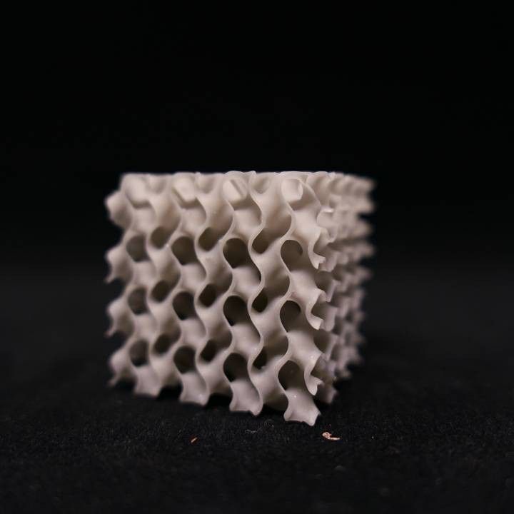 It is very similar to a skirt, but connected to the model. In addition to all the advantages of a skirt, the brim keeps the edges of the object being made on the table.
When printing, the outside of an object often cools faster than the middle, causing the edges to curl. Brim prevents this phenomenon by holding the edges.
Raft
A raft is a detachable base, made in the form of a thin mesh platform, located under the entire object (which lies on the raft). To create a raft, the printer first prints a flat plate in two or three layers, and then begins to manufacture the object. nine0008
The rafts provide excellent adhesion to the table surface and also provide a strong print base. This is especially useful when making small and oddly shaped parts that do not fit well on the table, as well as thin-walled objects.
After printing is completed, in most cases the raft will separate easily from the part.
If the printer does not have a heated desktop function
Rafts are used if the printer does not have desktop heating.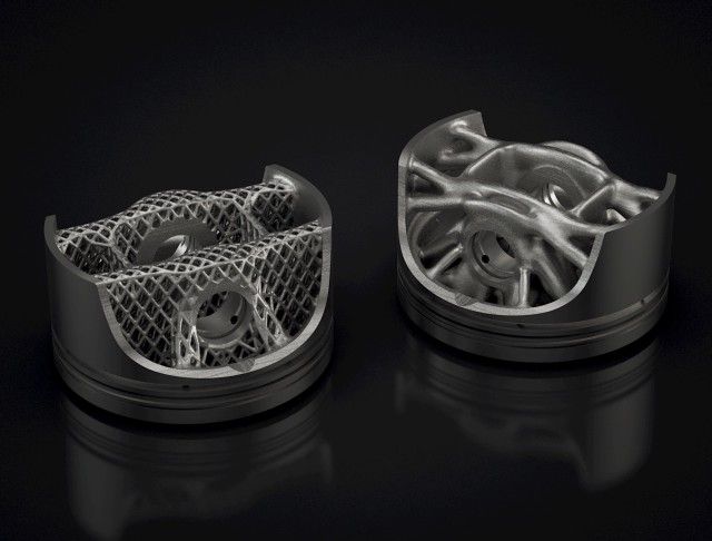 In this case, excessive adhesion becomes a problem. nine0008
An alternative method is to apply adhesive paper tape to the printer bed, with the edges down if possible (this also protects the bed). You can also use packing tape, but it is usually more expensive.
If buckling does occur or the object separates from the table, apply a dissolvable glue stick to the adhesive tape. This will enhance adhesion.
Find out the features of a specific 3D printer and take them into account when preparing a model
3D printing is not only a science, but also an art. Effective design for subsequent 3D printing requires an understanding of the technological process, taking into account its features and the purpose of the future object. This will greatly improve print performance. nine0008
Using Solid Edge in 3D printing
Not all CAD systems are suitable for 3D printing
The capabilities of the applied system should not limit the designers.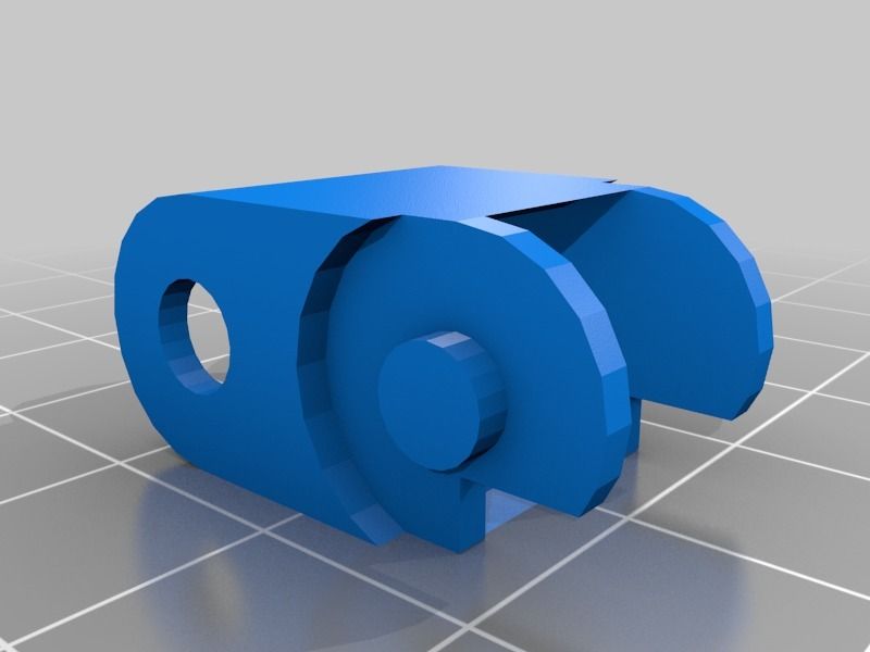 Our Solid Edge system is designed with the latest 3D printing technologies in mind. Various 3D printers and 3D printing services are supported.
Take it to the next level with specific techniques for designing 3D printed parts
Generative modeling in Solid Edge opens up new possibilities: the designer selects a specific material, sets the design space, allowable loads, restrictions and target mass of the part, and the system automatically calculates the desired geometry. As a result, 3D printing methods can produce the most complex shapes.
In addition, when building models, the use of the results of three-dimensional scanning is provided. Solid Edge successfully combines the traditional boundary representation of solid models (B-Rep) and the representation of surfaces in the form of a grid of triangles, which avoids time-consuming transformations that are fraught with errors. nine0008
If you've already downloaded an STL file for printing, our unique synchronous technology makes it quick and easy to edit your imported models in Solid Edge in preparation for the process.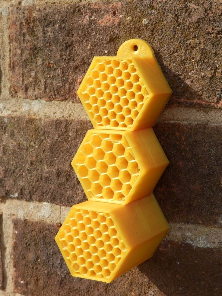
Printing with your own printer or submitting an order to a 3D printing service provider
Printing in Solid Edge on a local 3D printer is done using the 3D print command. Models can be saved in STL and 3MF formats, or sent directly to Microsoft 3D Builder. If you don't have your own 3D printer or need to try out different materials and surface finishes, Solid Edge allows you to directly submit your models to cloud-based 3D printing services (such as 3YOURMIND). You immediately receive quotes for the production of parts from various materials with its subsequent delivery directly to your door. nine0008
3D-CAD from Siemens from this article for 49900r (90% discount), the promotion is valid until March 20, 2020. Learn More>>
Steel 3D Printing - A Quick Guide
Any metal 3D printing technology can print with steel. This is the most popular material. But which steel grades and which technology is best for your application? Will printed steel parts really be as strong and durable as traditionally made parts? nine0008
Let's see how a 3D printed steel part revolutionizes manufacturing and opens the door to new applications in aerospace, medical equipment, automotive, tool making, heavy industry, architecture and more.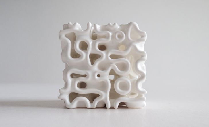 In addition, more affordable desktop printers are expanding the scope and scope of real steel 3D printed parts.
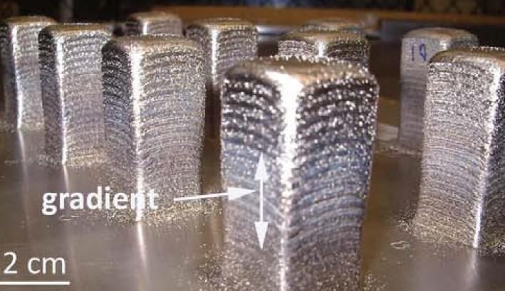
Strength of steel printed parts. nine0058 Cast steel part (left), 3D printed version (center). On the right, a fully 3D printed hinge requires no assembly. (Source: Desktop Metal)
The most common question when it comes to a 3D printed metal model is "Will it be as strong as a forged or cast part?" ?". The short answer is yes... and no.
3D printed steel parts can be just as strong, and sometimes even stronger, than those made in the traditional way. It depends on many factors such as: end use, type of steel, choice of 3D printing method, post-processing and shape of the part. Also, the comparison depends on which of the strength characteristics you focus on: tensile strength, static load strength, fatigue strength, etc. nine0008
Steel printed parts are used in the aerospace industry, the military, and for example the footbridge shown below. Therefore, the strength of printed products is beyond doubt, but let's take a closer look.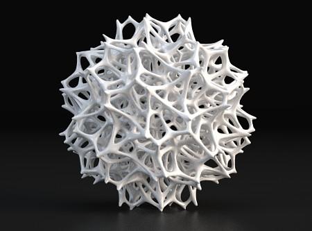
A 3D printed or laser powder sintered (LPBF) steel part has a finer grain structure than cast metal products. This provides better tensile strength characteristics, but in other respects the cast parts are currently still stronger. Most often, LPBF 3D printing is used to replace cast components, but in some cases, 3D printed components can replace forged parts. nine0008
One study showed that, under certain conditions, stainless steel parts made using LPBF 3D printers were three times stronger than parts made from the same steel using the traditional method.
In experiments comparing 3D printed steel parts to traditionally made steel parts, researchers create identical parts using two methods and compare their performance. However, head-to-head comparison of details is only part of the big picture. nine0008
The main advantage of printing with steel is not only its strength, but also the unique ability to create internal channels and lattice fillings in parts, which is not possible using traditional manufacturing methods.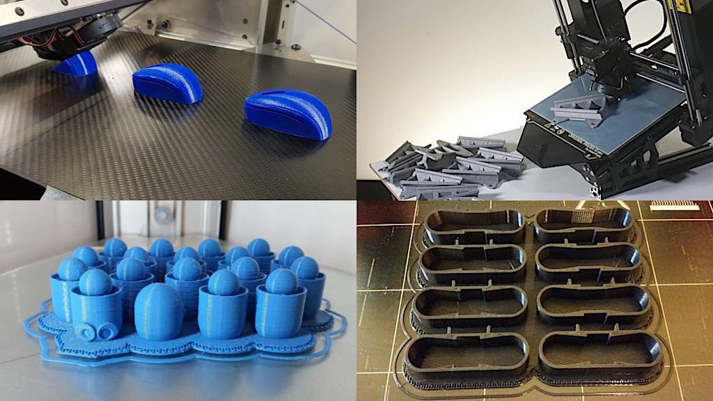 Metal 3D printing makes it possible to produce parts faster than traditional production, since this method does not require the use of special equipment and tools, it allows you to create assemblies as a whole, eliminating the need for subsequent assembly and welding. Designing a printed part usually means that less metal is needed to make it, and therefore less weight, for the same strength. nine0008 MX3D Wire Arc Additive Manufacturing (WAAM) printed steel architectural support (Source: MX3D)
Steel 3D printing is also more stable and cost effective as it reduces waste. When using subtractive manufacturing methods, such as CNC machining, you make a part by cutting it out of a large one, with a lot of waste. With additive manufacturing, you only use the material you need to make the finished product. nine0008
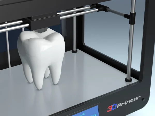
Steel 3D printing is not intended to replace traditional methods in all areas, but it may be a better choice for a wide range of applications. Particularly when the required parts are unique and designed for specific applications, such as rocket engines, racing cars or the oil and gas industry.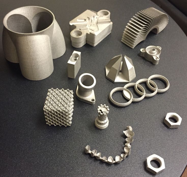 3D printing is the fastest and most flexible technology for mass production and prototype production. For military and industrial applications, steel 3D printing is a faster and more efficient way to create individual parts for vehicles and machines. Stainless steel 3D printing is rapidly finding applications in medicine to create unique surgical instruments and implants. nine0008
If you know what characteristics your final product should have (tensile strength, compressive strength, hardness, density, etc.), then all these parameters can be incorporated into the product at the production stage.
Types of steel for 3D printing
Metal powder is the most used metal material for 3D printing (Source: GKN Additive) There are thousands of different grades of steels and alloys with different mechanical properties, used in traditional manufacturing but in 3D printing there are only a few dozen of them, and some of them are unique, created specifically for this technology. Among the steel options, the following can be distinguished:
-
Stainless steel (316L, 304L , 17-4PH, 15-5PH, 420, 254, Ph2, GP1, 630, 410).
-
Tool steel (D2, M2, h23, h21, MS1, 1.2709).
-
Low alloy steel (4140).
-
Structural alloyed (20MnCr5).
Recently, unique alloys have been developed specifically for 3D printing, designed to solve the problems that occur with classical production methods. nine0008
For example, 3D printer manufacturer Desktop Metal released a patented stainless steel in 2022 that the company says combines the tensile strength, ductility, and corrosion resistance of 13-8 PH stainless steel, combined with the hardness low alloy steel like 4140. The company says customers can go to market with this material and skip the galvanizing step to protect products from corrosion.
ExOne offers two special blends of steel and bronze that the company says allows 3D printed steel parts to achieve increased corrosion resistance while being easy to machine and polish.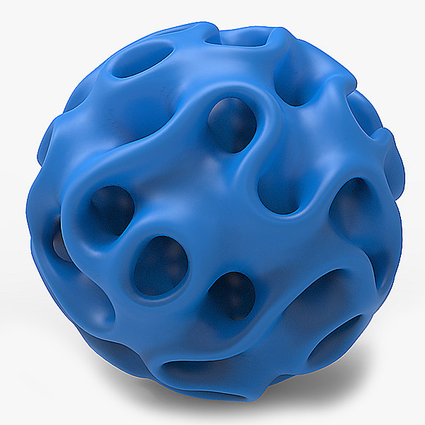 nine0008
While most of the metal powders used in 3D printing are similar to those used for other manufacturing methods, their numbers are on the rise as more companies adopt the technology. Some metal powder manufacturers, such as GKN, also make custom powders for specific 3D printing applications.
How to print with steel
The strength, properties, and applications of 3D printed steel products largely depend on which 3D printing technology you use. Some methods produce stronger parts, other methods provide better hardness or abrasion resistance, and some technologies are simply very fast. nine0008
Below are the main metal 3D printing methods, their properties and some of the most common application examples.
Fused Deposition Printing (FDM)
BCN3D's Epsilon printer extrudes metal filament from stainless steel (Source: BCN3D) as more printer manufacturers certify metallic filaments for use on their printers, such as Ultimaker, BCN3D, Makerbot, Raise3D.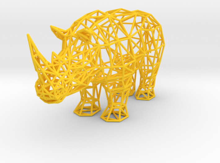 Raise3D has recently released a complete metal printing suite - Metalfuse (3D printer, debinding oven and sintering oven). This method is still much more popular for printing plastics, but with new plastic filaments filled with stainless steel powder, strong metal parts can be produced. nine0008
 FDM media was once limited to thermoplastics. Companies like BASF Forward AM and The Virtual Foundry now offer metal filaments that can be used on almost any FDM printer as long as it has a hardened steel nozzle for abrasive media.
These materials are approximately 80% metal and 20% plastic. After printing, the post-processing process removes the plastic, resulting in 100% metal parts. nine0008
Due to the removal of the bonding plastic, FDM metal parts shrink during post-processing. The amount of shrinkage is constant and can be taken into account in CAD systems, which allows to obtain relatively accurate finished parts.
Forward AM's 316L Stainless Steel Ultrafuse filament produces finished parts with material properties that the company claims are comparable to injection molded metal parts. nine0008 (Source: BCN3D)
While 3D printing with metallic materials may not be suitable for demanding applications such as aerospace, the economics of producing simple metal components without critical loads on an affordable FDM printer can outweigh the impossibility of applying them in some areas.
Metal prototype parts and finished parts that will not be subjected to extreme stress are ideal uses for this technology. nine0008
Bound Metal Deposition (BMD)
Desktop Metal's Studio System 3D printer used bonded metal bars that were extruded layer by layer to form a metal part (Source: Desktop Metal) Similar to FDM, Metal mesh deposition method (BMD) or bonded powder extrusion (BPE) is a 3D printing process based on extrusion. This method uses bonded metal rods or bonded powdered metal filaments, which consist of a much higher percentage of metal powder than the filaments used in FDM. As with FDM, post-treatment to remove the binder and heat treatment in a final sintering oven are required.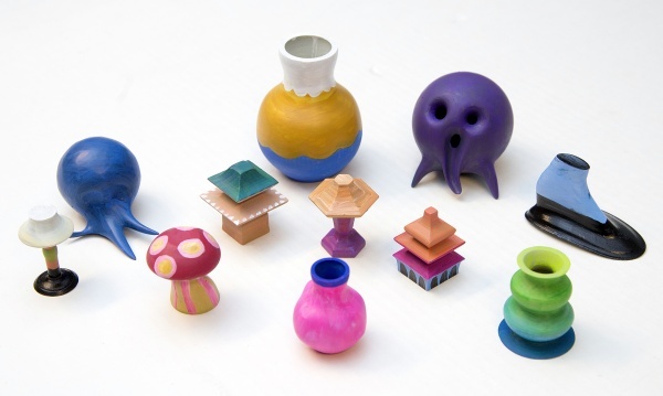 nine0008
There are only a few 3D printers using this method such as Desktop Metal, Markforged and more recently 3DGence, but more companies are entering this market, so stay tuned. These printers are valued as a convenient solution for office 3D metal printing, they are more expensive than most FDM printers, but cheaper than the powder-based metal 3D printing technologies described below.
These printers use their own proprietary filament. Desktop Metal and Markforged offer four types of steel. nine0008
Ideal niches for this technology are metal prototype parts, where it is necessary to test the functionality of a part before mass production using traditional methods. Popular applications are molds, punching dies, nozzles, impellers, fasteners and heat exchangers.
For example, Shukla Medical uses Markforged's Metal X printer to print steel prototypes of its orthopedic implant removal instruments. nine0008
Laser powder sintering.
Laser powder sintering technology uses one or more lasers to melt powdered metal into a desired shape layer by layer (Source: GE Additive) metal printing. This technology is used by 80% of all metal 3D printers on the market.
 This method uses powerful lasers to selectively sinter metal powder layer by layer. nine0008
LPBF 3D printers are available in a wide range of sizes, prices and laser powers. These and other characteristics affect the properties of the finished part, print speed and other parameters of the finished products.
Steel and steel alloys are the most popular material for LPBF equipment and, unlike FDM and BMD, metal powders are commercially available as they are most commonly used in traditional production methods.
LPBF is a technology that maximizes the quality of a 3D printed part. Applications include aerospace components such as monolithic thrust chambers, rocket engine components and heat exchangers, molds, tools and other applications, as well as high wear parts and surgical instruments. nine0008
Binder Jetting
Binder Jetting 3D printing technology uses powdered metal and a binder to form metal parts (Sorrce: ExOne) binder, and not with a laser. During post-processing, the binder is removed.
 Binder application stands out for its high printing speed compared to other 3D printing methods or conventional manufacturing, and metal parts made with this technology have material properties equivalent to parts made by metal injection molding. nine0008
The number of manufacturers producing metal-bonded inkjet 3D printers is much smaller than that of LPBF machines. Leading manufacturers include ExOne, Desktop Metal, Digital Metal, GE Additive and HP.
Binder blasting is ideal for medium to high volume production of metal tools and spare parts.
In fact, HP claims that its Metal Jet 3D printer was designed specifically for mass production of 316L stainless steel products. HP has partnered with Parmatech to produce metal parts for the medical industry. Pennsylvania-based ExOne uses this technology to manufacture hard metal cutting tools and tool steels. nine0008
Electron Beam Melting (EBM)
(Source: GE Additive) Electron Beam Melting (EBM) is another powder cladding technology.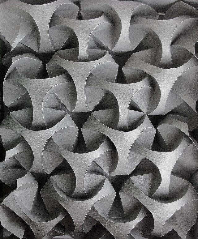 It works in a similar way to selective laser melting (SLM), but instead of using a laser as the energy source, it uses a much more powerful beam of charged particles.
The recoater moves the powder onto the printing plate and an electron beam selectively melts each layer of powder. After each layer is printed, the plate is lowered and another one is applied on top of the previous layer. nine0008
EBM can be much faster than SLM, but SLM produces smoother and more accurate pieces. The electron beam is wider than the laser beam, so EBM cannot produce the same precise parts as SLM. Another difference is that the manufacturing process takes place in a vacuum chamber, which reduces the amount of impurities in the material that can lead to defects. That is why EBM is often chosen for printing components for the aerospace, automotive, defense, petrochemical and medical implant industries. nine0008
Titanium is the most popular metal for most EBM applications, however steel can be used.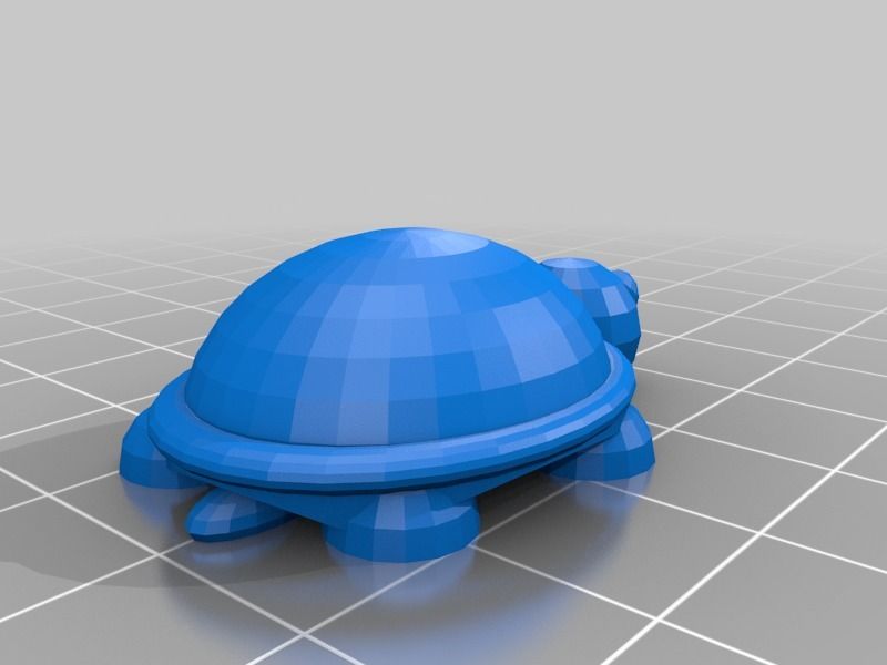
Cold Spray
(Source: Impact Innovations)Cold spray 3D printing is done by injecting metal powders through a jet nozzle into a supersonic stream of pressurized gases such as air, nitrogen, or helium. The process is called "cold" because the metal particles do not melt, but hit the metal substrate and adhere to its surface during the so-called plastic deformation. nine0008
Cold spray printed products are not prone to porosity, thermal cracking and other defects associated with melt-based technologies. This method has several advantages over other production methods. The technology is used in the military and aerospace industries around the world. For example, the US Army uses cold spray to repair the mounts of a worn Bradley 25mm steel turret gun.
In the automotive industry, cold spray steel is used for crash repairs because the high strength steel substrates in automobiles can be susceptible to thermal repair methods such as welding. nine0008
Direct Energy Deposition (DED) and Wire Arc Additive Manufacturing (WAAM)
WAAM Steel Parts from MX3D (Source: MX3D) Direct Energy Deposition (DED) uses welding powder or wire that enters through a nozzle and is fed into the power source to melt the metal.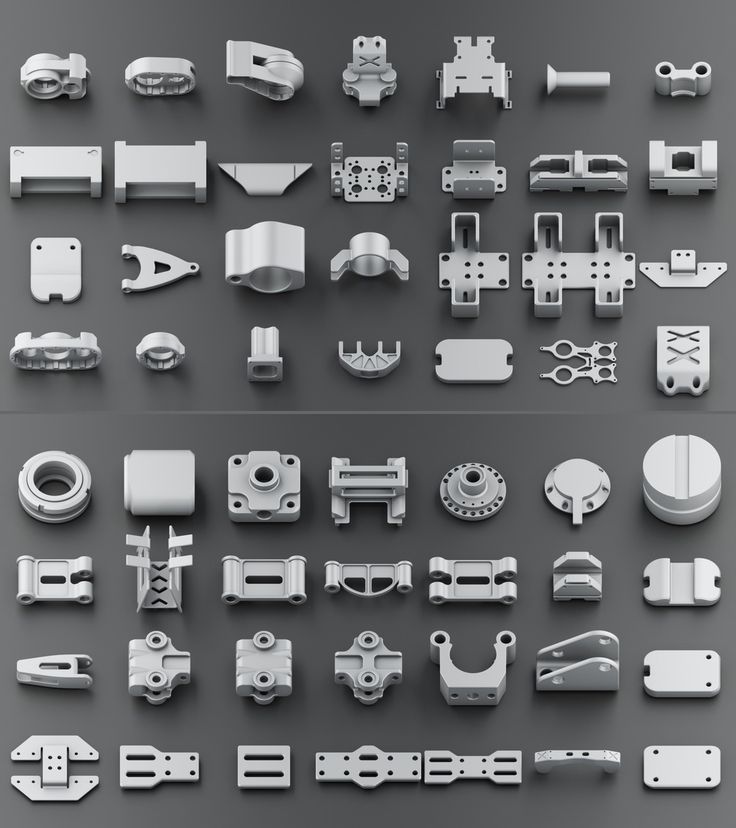 A melt region is created and applied to the substrate. DED is a new process, reminiscent of an old building technology known as "cladding", in which a coating is applied to a substrate, often for thermal insulation or weather resistance. DED is useful for fabricating large objects as a whole, as well as complex geometries that require extensive machining. DED can get such parts much closer to finished than traditional CNC machining. nine0008
Because DED uses a coating process, it can be used to add complex geometries to existing steel parts, thus combining complexity with cost reduction. For example, the French company AddUp advertises a rocket nozzle that uses a preformed large 304 stainless steel hopper cone printed with an isogrid structure, usually made from a larger piece by traditional methods.
A technology related to DED is wire-arc additive manufacturing (WAAM). Instead of powder, WAAM uses a metal wire that is melted by an electric arc. The process is controlled by robotic arms. WAAM is also capable of producing large-sized metal parts, as demonstrated by the Dutch company MX3D and its nine thousand-pound 41-foot stainless steel bridge in Amsterdam, as well as an oil and gas equipment repair part, proving that parts can be made in the field. nine0008
Micro 3D printing
Micro parts printed from steel (Source: 3D MicroPrint)Micro scale additive manufacturing, or micro 3D printing, can produce products with a resolution of a few microns (or less). There are three micro 3D printing methods to produce metal parts.
LMM (lithography-based metal fabrication) is a light-based technology that creates tiny parts from raw materials, including stainless steel, for applications such as surgical instruments and micro-mechanical parts. nine0008
Electrochemical deposition is the latest micrometal 3D printing process developed by the Swiss company Exaddon. In this process, the printing nozzle applies liquid with metal ions, creating details at the atomic level.