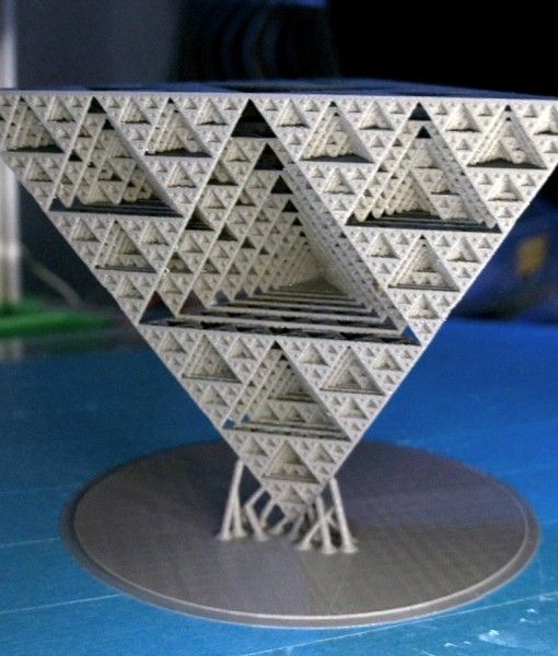
3D print geometry
Geometric best 3D printer files・Cults
Long Octogon 2 Clay Cutter - Mid Century Modern STL Digital File Download- 10 sizes and 2 Cutter Versions
€2.28 -20% €1.82
Long Octogon 1 Clay Cutter - Mid Century Modern STL Digital File Download- 10 sizes and 2 Cutter Versions
€2.28 -20% €1.82
Three Circles 1 Clay Cutter - Mid Century Modern STL Digital File Download- 10 sizes and 2 Cutter Versions
€2.28
Curved Triangle 4 Clay Cutter - Mid Century Modern STL Digital File Download- 8 sizes and 2 Cutter Versions
€2.28 -20% €1. 82
Curved Triangle 3 Clay Cutter - Mid Century Modern STL Digital File Download- 9 sizes and 2 Cutter Versions
€2.28 -20% €1.82
French Bulldog Dog Lowpoly
€0.60
Birds Sculpture
€0.60
Elephant Sculpture
€0.60
Bull Sculpture
€0.60
Horse Sculpture
€0.60
Horse Sculpture
€0.60
Cat Sculpture
€0.60
Elephant Sculpture
€0.60
Birds Sculpture
€0. 60
60
Horse Sculpture
€0.60
Goat Sculpture
€0.60
Shark Sculpture
€0.60
Horse Sculpture
€0.60
Deer Sculpture
€0.60
Ornament Elephant Sculpture
€0.60
Horse Sculpture
€0.60
Camel Sculpture
€0.60
Low Poly Dog - Doberman
€19 -50% €9.50
Lion's Female Head Lowpoly
€0.60
Mountain Goat
€0. 60
60
Curved Triangle 2 Clay Cutter - Mid Century Modern STL Digital File Download- 9 sizes and 2 Cutter Versions
€2.28 -20% €1.82
Curved Triangle 1 Clay Cutter - Mid Century Modern STL Digital File Download- 10 sizes and 2 Cutter Versions
€2.28 -20% €1.82
Boho Shape 2 Clay Cutter - Mid Century Modern STL Digital File Download- 8 sizes and 2 Cutter Versions
€2.28 -20% €1.82
Boho Shape 1 Clay Cutter - Mid Century Modern STL Digital File Download- 8 sizes and 2 Cutter Versions
€2. -20% €1.82 28
28
Crystal 1 Clay Cutter - Witchy Magic STL Digital File Download- 8 sizes and 2 Cutter Versions
€2.28 -20% €1.82
Giraffe low poly decorative painting
€0.75
Frill Heart 3 Clay Cutter - Valentines Love STL Digital File Download- 8 sizes and 2 Cutter Versions
€2.39 -20% €1.91
Frill Heart 2 Clay Cutter - Valentines Love STL Digital File Download- 8 sizes and 2 Cutter Versions
€2.28 -20% €1. 82
82
Frill Heart 1 Clay Cutter - Valentines Love STL Digital File Download- 10 sizes and 2 Cutter Versions
€2.28 -20% €1.82
Boiled Egg 1 Clay Cutter - Breakfast Food STL Digital File Download- 10 sizes and 2 Cutter Versions
€2.39 -20% €1.91
Blank Easter Egg 1 Clay Cutter - Breakfast Food STL Digital File Download- 10 sizes and 2 Cutter Versions
€2.28 -20% €1.82
Candle holder mold
€2.30
Fox geometric decoration
€1. 02
02
Low Poly Heart Bowl
€1.15
Fried Egg 1 Clay Cutter - Breakfast Food STL Digital File Download- 9 sizes and 2 Cutter Versions
€2.39
Heart Frill 4 Clay Cutter - Valentines STL Digital File Download- 8 sizes and 2 Cutter Versions
€2.39 -20% €1.91
Heart Frill 3 Clay Cutter - Valentines STL Digital File Download- 8 sizes and 2 Cutter Versions
€2.39 -20% €1.91
Heart Frill 2 Clay Cutter - Valentines STL Digital File Download- 8 sizes and 2 Cutter Versions
€2. -20% €1.82 28
28
Heart Frill 1 Clay Cutter - Valentines STL Digital File Download- 8 sizes and 2 Cutter Versions
€2.28 -20% €1.82
Pack Bundle 5 Low- Poly Animal STL File 5 3d Printable Toys 3D print model
€6.43
geometric jack
€0.62
Vase 1001 - Bulb vase
€1.66 -35% €1.08
Flower 19 Clay Cutter - Botanical STL Digital File Download- 8 sizes and 2 Cutter Versions
€2.28 -20% €1. 82
82
What can’t 3D printers do? Understanding and overcoming 3D printing geometry limitations
What are the limitations of modern 3D print manufacturing? This article covers the major factors that will affect the quality of your 3D-printed part, including size, element thickness, how watertight it is (manifold) and curved surfaces. Read on to understand the limitations of 3D printing.
3D printers are enormously flexible in the kinds of parts they can produce. Depending on the type of printing technology, you can manufacture parts of many different sizes and geometries. However, even the most advanced 3D printing methods have their limitations.
This article explores geometric and size limitations you should understand when designing 3D models in CAD to be manufactured with additive technologies . These limitations are important to consider whether you’re producing basic mechanical components or super complex parts (and anything in between).
We also have a comprehensive step-by-step guide on exporting your 3D models into the STL file format.
What’s the typical build size of 3D printers?
One of the major limitations that every 3D printing technology faces is the size of the part it can create.
Of course, this will differ depending on the kind of printer you’re using to manufacture parts, though a good rule of thumb is to use an industrial printer for more sizable parts. We also recommend splitting parts into two or more components to be printed separately and assembled after. Both of these options will affect the final cost.
The table below showcases the typical build size of the 3D printing processes we offer at Hubs (and through Protolabs in the case of metal 3D printing ).
| Typical build size | |
|---|---|
| FDM | 200 x 200 x 200 mm for desktop printers; Up to 900 x 600 x 900 mm for industrial printers |
| SLA | 145 x 145 x 175 mm for desktop printers; Up to 1500 x 750 x 500 mm for industrial printers |
| SLS | 300 x 300 x 300 mm (up to 750 x 550 x 550 mm) |
| DMLS/SLM | 250 x 150 x 150 mm (up to up to 500 x 280 x 360 mm) |
| MJF | 380 x 285 x 380 mm (14. 9'' x 11.2'' x 14.9'') 9'' x 11.2'' x 14.9'') |
Minimum wall thickness for optimal printability
Another major factor to keep in mind when designing a part for 3D printing is the thickness of all the walls. Every 3D printing process has a standard minimum wall thickness (or at least a highly recommended one).
In general, it’s impossible to print very thin features unless they are wider than the minimum printable feature size for a given additive process. We often see architects and game designers attempting to produce elements in a 3D model with infinitesimal thicknesses (think hair, capes and sails). This is challenging for even the most advanced printer, so be aware of this particular limitation.
The table below summarizes the recommended minimum wall thickness for the most common 3D printing technologies. Note that in some cases, like SLA , it’s possible to print smaller features, but this should be assessed on a case-by-case basis.
| 3D printing process | Recommended Minimum Wall Thickness |
|---|---|
| FDM | 0. 8 mm 8 mm |
| SLA/DLP | 0.5 mm |
| SLS | 0.7 mm |
| MJF | 0.5 mm |
| DMLS/SLM | 0.4 mm |
Why should a 3D model be manifold or watertight?
Every 3D model intended for 3D printing should be completely manifold (aka watertight), meaning that every edge should be connected to exactly 2 polygons and the model must include no holes (unless they’re integral to the design).
Models that are not manifold might get misinterpreted by the software that generates the instructions for the 3D printer (slicer). A non-manifold 3D model might cause the print itself to have inconsistent layers, holes or other errors. This will render your desired object very likely unprintable.
Let’s quickly break this down. Every model is built out of polygons, which are also called faces. These are the flat squares you see in polygonal models (non-CAD models). Every sigle polygon is the surface between 3 or 4 edges, and every one of these edges needs to have 2 polygons connected to either side of it.
Still wondering why we call models watertight, though? The reason is that if you were to fill an object up with water, a manifold model wouldn’t let a drop of it escape. This doesn’t have anything to do with whether a 3D object is water resistant or can survive being submerged for prolonged periods.
Non-manifold issues are often not visible at the modeling stage. The simplest way to check whether a model is printable is to use an analyzer software, like Netfabb or Meshmixer. These programs detect model features that will cause issues at the 3D printing stage and offer repair options (without impacting the overall geometry of the model).
Also when you upload a part to print with Hubs , our automatic tools will check whether a design is printable with the most common 3D printing processes and we will show you the areas that have errors.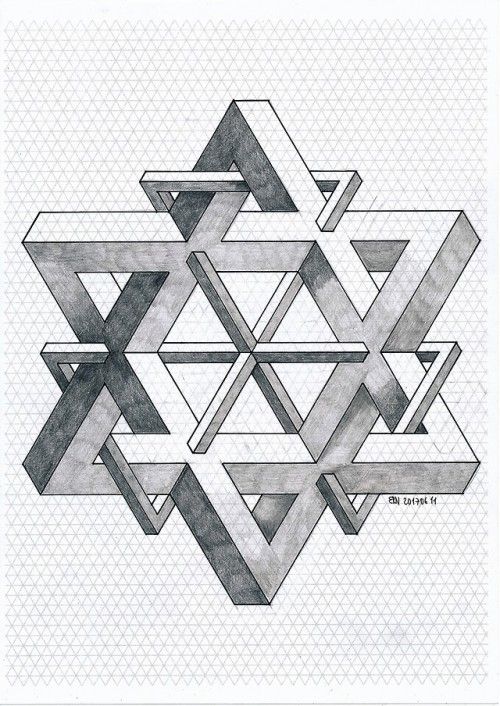
What are NURBS? Practical tips for printing smooth surfaces
Most CAD modeling software , such as Solidworks and Fusion360, use Non-uniform Rational Basis Splines (NURBS) to display the surfaces of a 3D model. When exporting your model to the STL file format for 3D printing it’s important that an adequate number of polygons are used to represent its surfaces. This will ensure that your part will be 3D print with a smooth appearance.
If the 3D model is exported with too few polygons, the edges connecting individual polygons will often be visible in the final 3D-printed part. This effect is more prominent with large models (larger than 300 mm3), where the polygons become more visible on curved surfaces.
If you export your 3D model with too many polygons, then the file size will be too large and difficult to handle for most printers. When you create meshes of polygons, the finer the mesh (meaning more polygons), the bigger the file size, so anything below that threshold will not print (or won’t print to the right quality level).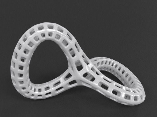
Luckily, most modeling software export 3D models with an adequate number of polygons using the preset, resulting in smooth 3D-printed parts. If a higher polygon count is required, the export settings can be adjusted accordingly.
3D model of a sphere with a low polygon countReady to explore what's possible with 3D print manufacturing?
Our online 3D printing service Upload a CAD file for a free, instant quote
Ready to transform your CAD file into a custom part? Upload your designs for a free, instant quote.
Get an instant quoteGeometry, not everything is so simple
Personal diaries
Subscribe to the author
Subscribe
Don't want
2
Geometry .... seemed like an exact science to me at school.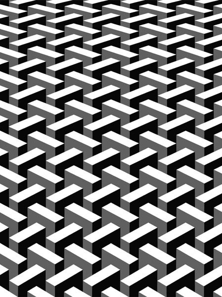 Until I got a 3D printer.
print gurus and those whose printer prints 'out of the box' everything is exactly the size in size is not worth reading.
Prehistory. For about a year, with varying success, I have been mastering 3D printing. The printer (the first) is a pruche-like Chinese whale FLSUN, which, after minor modifications, began to give me quite acceptable print quality. In the beginning there was PLA plastic and, of course, a lot of marriage ... or these were just tests. When it came to modeling parts for which connections, joints, were subsequently planned, I encountered the phenomenon of a size difference in the size of internal holes. As a rule, the difference was up to 0.4 -0.6 mm (X and Y axes, of course, there were no such problems in Z, or insignificant on high parts), with the same external dimensions. After reading the information, asking for 3d thudey, I found out for myself that this is due both to errors in the mechanics of the printer, and to the phenomenon of plastic shrinkage.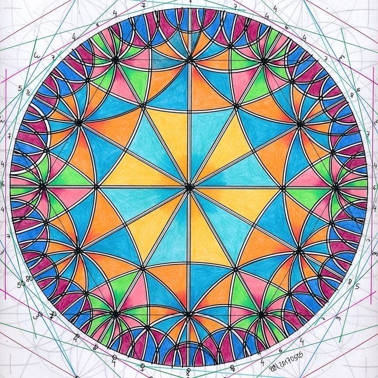 In general, I reconciled myself and manually made corrections for the difference during modeling, or made trial parts of the parts, measured them and, after correcting, put them into print. nine0003
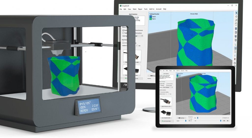
By the way, the slicing was done either by Cure or in Simplify3d.... it didn't change anything. I settled on Cura for this printer, it's more convenient. On the second (because of Sailfish) I use Simplify3d.... it's more convenient there
BUT nothing lasts forever under the moon.
I switched from affordable pla to ABS, also tried PETG printing, the principle in building models was the same. Everything more or less worked out. Until the next reel of GREG PLA plastic, despite the fact that before that I had already printed three reels of a different color from this manufacturer. Generally blue. Strange properties, not very similar to PLA - less brittle, easier to cut with a clerical knife .... and does not require correction of parts - an error of 0.1 - 0.05 mm on internal dimensions (up to 0. 6 mm before. After the test, printing the necessary details, put the coil on NZ, no laughing0003
Returned to 'normal'.
I decided to stir up a more complex project with a large number of printed parts, I made a project in SolidWorks. And since pairing with tolerances ... or whatever it is called ..... I can’t do it. Therefore, all the details were made in absolute dimensions. It came to printing ... and it turns out a lot of the details need to be edited. and then redraw. So the question arose .... is there a way to improve this? How to model details in the program, if you know that you will need to adjust the dimensions before printing. If she is alone, then this is not long, but if there are many of them? It is interesting to know how it copes (who has a similar problem). nine0003
Having printed out a stand for a drill designed by mister Magomedov from PLA, I was pleased with the result. But there was no nylon on hand (enough). But I decided to try later. And the other day I decided to make a test part from a new project from nylon, more precisely from a trimmer fishing line. After tests with print parameters, I kicked out the first part, but there were several delaminations, either the temperature of the extruder, or the heat chamber was bad. In general, I slightly increased the printing temperature and added a casing during printing, removed the retract (it seems worth leaving, but minimal) .... and a good detail came out .... errors in the departure and table along the edges (until I picked up a suitable adhesive intermediary), but didn't get any splits. The part is strong - it didn’t break with hands and teeth))
And pretty yellow. Until I took the barbell in my hands (I made the correction as usual)
But the photo is visible
..... inserted at random.
in general - the error in most cases by 0.5 mm is easy to correct (according to external dimensions). But the detail (in the section of a right-angle, which was supposed to be put on a profile 25 mm al pipe) has a difference in internal dimensions of 1. 2 mm. I didn't expect this.
What are the properties of plastic? I realize. that it is not intended for 3D printing, but ... I have a large coil. gotta use it somehow0003
Second printer without heated bed, I can't try it there
Subscribe to the author
Subscribe
I do not want
2
3D printing-3dprinter
Geometry 3D printing
This article discusses the dimensions and geometric restrictions that must be taken into account when determining the determination of it. whether 3D model for 3D printable . These recommendations should be taken into account by everyone who wants to get a high-quality model at the end. nine0003
Physical size
The table below shows the typical build size of the most common 3D printing processes . It is important to note that printing large parts usually requires an industrial printer, adding to the overall cost. Alternatively, the model can be split into 2 or more pieces, which can be printed separately and reassembled later.
Typical assembly size
FDM 200 X 200 x 200 mm for desktop printers
to 900 x 600 x 900 mm for industrial printers
SLA/DLP 145 x 145 x 175 mm for desktop
to 1500 x 750 x 500 mm for industrial printers
SLS 300 x 300 x 300 mm
(up to 750 x 550 x 550 mm)
Minimum Wall Thickness
The walls of the object must be thicker than or equal to the nozzle itself (usually 400 microns) that you will use when you print the model. If you specify smaller sizes, then the printer will not be able to print them. The thickness of the wall depends on the number of perimeters that will be printed. So, when there are 2 wall perimeters and a 0.5mm nozzle, the wall thickness that will be printed will be 0.5, 1, 1.5, 2mm. That is, the thickness must correspond to the diameter of the nozzle, if it is less than N * d (N is the sum of the perimeters, d is the diameter of the nozzle).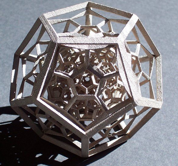 nine0003
The table below shows the recommended minimum wall thickness for the most common 3D printing technologies. Please note that in some cases, such as SLA/DLP, smaller details can be printed.
Recommended Minimum wall thickness
FDM 0.8 mm
SLA/DLP 0.5 mm
SLS 0.7 mm 900.7 mm
Curved surfaces
Most CAD modeling programs such as Solidworks and Fusion360 use Rational Basis Non-uniform Splines (NURBS) to display the surfaces of a 3D model. NURBS - NURBS surfaces are defined by curves that are affected by "heavy" control points. The curve follows (but does not necessarily touch) the points. Increasing the weight of a point will draw the curve closer to it. NURBS are actually smooth surfaces, not imitations of them with small flat surfaces, so this technique is often used to model organic shapes
When exporting your model to STL format for 3D printing it is important that enough polygons are used to represent its surfaces.