3D metal printing tolerances
Metal 3D Printing Design Guidelines
Back
-
Materials
Materials by Service
Injection MoldingCNC Machining3D PrintingSheet Metal
Materials by Type
PlasticsMetalsElastomers
Related Links
Customer Supplied ResinsColors
Injection Molding Material Alternatives Guide
Struggling with thermoplastic material shortages? We created a detailed guide to resin substitutes for ABS, PC, PP, and other commonly molded thermoplastics.
Download
-
Resources
Design Tips Guides and Trend Reports Case Studies Design Aids Webinars and Trade Shows
Blog Videos FAQs Educators and Students Glossary
Industries Medical Aerospace Automotive Consumer Electronics Industrial Equipment
-
About Us
Who We Are Why Protolabs? Research and Development Cool Idea Award Partnerships Sustainability and Social Impact
Careers Investors Locations Press Procurement
Contact Us
Proto Labs, Inc.
5540 Pioneer Creek Dr.
Maple Plain, MN 55359
United StatesP: 877.479.3680
F: 763.479.2679
E: [email protected]Best-in-Class Online Quoting
After uploading your part design, you'll receive an online quote that includes manufacturing analysis to help improve part manufacturability. Within your quote, you can also adjust quantity and material and see price changes in real-time.
Learn More
Get a QuoteSign In
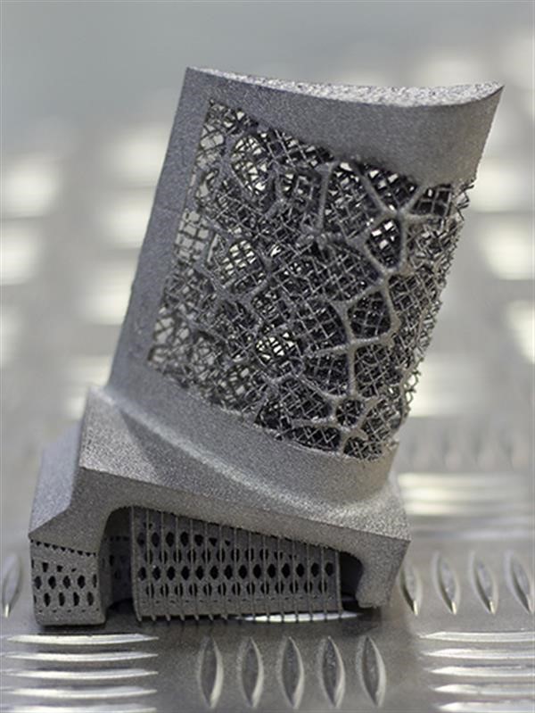
Our basic guidelines for direct metal laser sintering include important design considerations to help improve part manufacturability, enhance cosmetic appearance, and reduce overall production time.
Maximum Dimensions
- IN
- MM
| Normal Resolution | 9.6 in. x 9.6 in. x 13.0 in. |
|---|---|
| Normal Resolution (X Line*) | 31. 5 in. x 15.7 in. x 19.7 in. 5 in. x 15.7 in. x 19.7 in. |
| High Resolution | 3.5 in. x 3.5 in. x 2.7 in. |
| Normal Resolution | 245mm x 245mm x 330mm |
|---|---|
| Normal Resolution (X Line*) | 400mm x 800mm x 500mm |
| High Resolution | 88mm x 88mm x 70mm |
*These parts can only be built in Inconel 718
Accuracy
Layer Thickness
- IN
- MM
| Normal Resolution | 0.00118 in. |
|---|---|
| Normal Resolution (X Line) | 0.00236 in. |
| High Resolution | 0.00079 in. |
| Normal Resolution | 30 microns |
|---|---|
| Normal Resolution (X Line) | 60 microns |
| High Resolution | 20 microns |
Minimum Feature Size
- IN
- MM
| Normal Resolution | 0.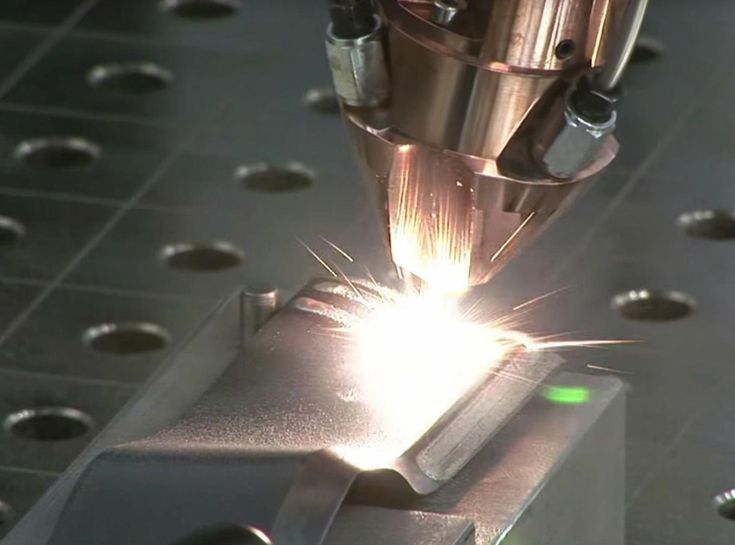 015 in. 015 in. |
|---|---|
| Normal Resolution (X Line) | 0.030 in. |
| High Resolution | 0.006 in. |
| Normal Resolution | 0.381mm |
|---|---|
| Normal Resolution (X Line) | 0.762mm |
| High Resolution | 0.153mm |
For well-designed parts, tolerances of ±0.003 in. (0.076mm) plus ±0.001 in./in. (0.001mm/mm) for each additional inch can typically be achieved. Note that tolerances may change depending on part geometry.
Design Essentials for 3D Printing
The 3D Printing Essentials reference guide offers guidelines and key considerations when designing for industrial 3D printing processes.
DOWNLOAD >
3D Printing Surface Finish Guide
Download this quick reference guide that looks at all of your surface finish options across our six additive manufacturing technologies.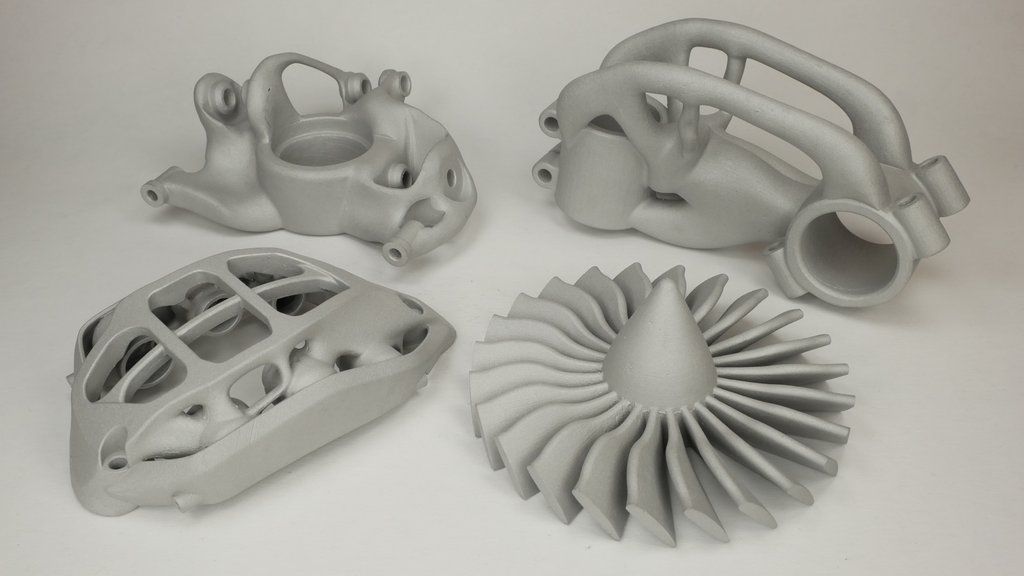
DOWNLOAD >
Materials
- Aluminum / AlSi10Mg
- Cobalt Chrome
- Inconel 718
- Stainless Steel 17-4 PH
- Stainless Steel 316L
- Titanium / Ti 6-4
- Copper / CuNi2SiCr
VIEW MATERIALS >
Surface Finishes
| STANDARD | Expect roughness values of 200 to 400 µin Ra (0.005 to 0.010mm Ra), depending on material and resolution. |
|---|---|
| CUSTOM | Secondary options include hand-polished or machined surfaces upon request. When tighter tolerances are required, we can provide secondary machining operations such as drilling, slotting, milling, and reaming. |
Production Capabilities
Improve strength, dimensional accuracy, and cosmetic appearance of final metal components with DMLS for production.
Post-Machining
- 3- and 5-axis milling
- Turning
- Wire EDM
- Tapping and reaming
Powder Analysis & Material
- Traceability
- Chemistry
- Particle size and distribution analysis
- Mechanical coupon testing
Mechanical Testing
- Tensile
- Rockwell Hardness
- Fatigue
- Vibration
Heat treatments
- Stress relief
- Hot isostatic pressing (HIP)
- Solution annealing
- Aging
VIEW PRODUCTION CAPABILITIES >
Equipment
We use GE Additive Concept Laser Mlab, Mlab 200R, M2, and X Line 2000R machines for DMLS production that offer large build sizes, produce accurate parts, and provide quick turnaround times.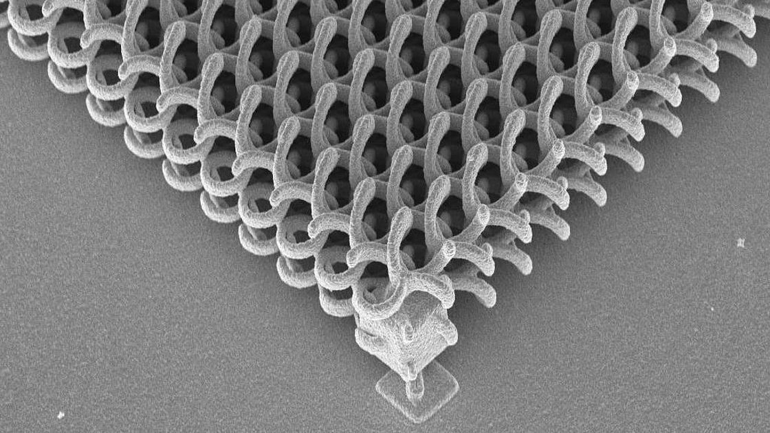 The Mlab and Mlab 200R are ideal for manufacturing metal components with elaborate structures, and they are ideal when high surface quality and fine component structures are needed on parts. The M2 is a large platform machine that is able to produce larger metal parts than the Mlab, and the X Line 2000R can produce parts with build volumes as large as 800mm by 400mm by 500mm. All of our 3D printing equipment can handle both reactive and non-reactive metal powder.
Get A Quote
Request More Information
Thanks! We’ve received your message and a member of our team will be in touch with you shortly.
You can find more information about Protolabs here:
- Manufacturing Services
- Material Comparison Guide
- Free Design Aids
Thanks for your interest in Protolabs. Please let us know how we can provide more information on our services. Once we receive your comments, an applications engineer from our team will follow-up as soon as possible.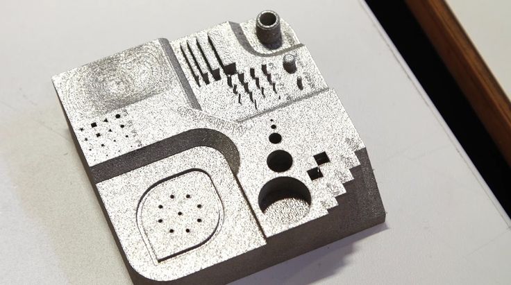
If you have a 3D CAD model of your part ready, upload it online now to receive an interactive quote with free design for manufacturability feedback within hours.
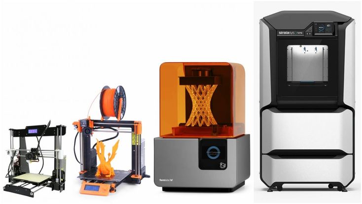
Accuracies and tolerances in 3D printing
Our daily business is rapid prototyping and small series production. Hundreds to thousands of prototypes and end-use parts are sent daily from our production facilities to engineers and product developers all over the world. When discussing a project, the most frequently discussed issue is that of the appropriate procedure or material. There are many factors that influence this choice, but most often the following:
- Costs: the cost per piece is calculated based on quantity and geometry of the part
- Production speed: with technologies like Stereolithography parts can be produced overnight, thermal technologies (e.g. Multi Jet Fusion / High-Speed Sintering HSS) take about 3 – 4 days
- Material properties: mechanical, chemical & heat resistance
- Desired visual effects: color, surface quality, etc.
- Accuracy / tolerances: typical deviations of the printed parts vs. the base dimensions
While the exclusion principle can often be applied to the first four factors, the question of accuracy / tolerance is often more complex. In the following article we will give you a brief overview of what you need to bear in mind when thinking about the accuracy and tolerances of 3D printing.
General information about tolerances in 3D printing
In most additive technologies, the dimensional tolerance is at least 0.1 mm. This means that the deviations in 3D printing are greater than in other technologies, such as injection molding or CNC machining. While tolerances of 0.1 mm are not uncommon when injection moulding plastics, it is quite possible to work in the hundredth scale when machining metal.
A common misunderstanding is the swapping of resolution and tolerance. If a Polyjet printer has e.g. resolutions (in Z direction) of only 15 µm, this does not mean that the tolerance is correspondingly low.
Error #1: STP -> STL conversion
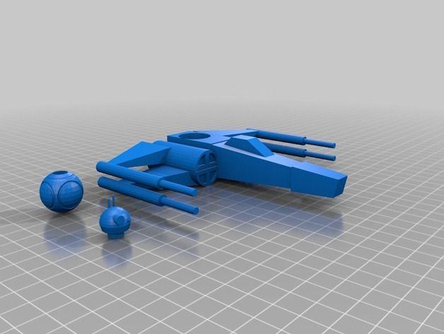
In order to be used for 3D printing, an STL file must be available. This is exported from a CAD software or converted from a CAD file. Typical file format is the STP format. When converting STP to STL, inaccuracies in the hundredth scale can occur.
There is a particular problem with the surface. As this converts an algorithm (STP) into a ‘mesh’, in simple terms into a network of triangles, the interface therefore needs to be simplified. The lower the resolution is selected, the greater the deviation from the desired state. On the other hand, if the resolution is too high, the models get such enormous sizes that they can no longer be processed.
If you are not sure which resolution to choose, simply send us the STP file, we will choose the technically maximum possible resolution.
Export Resolution: 0,8
File size: 0,01 MB
Export Resolution: 0,1
File size: 0,03 MB
Export Resolution: 0,01
File size: 0,5 MB
Export Resolution: 0,001
File size: 3,7 MB
The conversion of a sphere from STP to STL format with increasing resolution from left to right. The resolution is selected according to the size and general complexity of the component. The two medium resolutions are sufficient for most components.
Error #2:
3D printing tolerances according to process
- SLA (Stereolithography): ± 0,2 % (with a lower limit of ± 0.2 mm)
SLA is the most accurate method with Polyjet. The diameter of the laser is usually around 100 -150 µm and is therefore significantly smaller than, for example, in the FDM process. Tolerances occur mostly due to shrinking. Attention with thin large surfaces, these can (as with most procedures) partly significantly warp. - DLP: ± 0,1 – 0,2 % (with a lower limit of ± 0.1 – 0.2 mm)
DLP works basically like stereolithography, only that here projectors are used instead of lasers. The tolerance depends on the resolution. Devices with very small installation spaces (= 10 cm side length). At this size, the systems generally have tolerances of around 0.1 mm.
- SLS (Selective Laser Sintering): ± 0,3 % (with a lower limit of ± 0.3 mm)
SLS is one of the most popular rapid prototyping technologies. This is particularly due to the design flexibility (no support structures) and the robust material. This process works with heat, which unfortunately can lead to shrinkage or warpage. - HP Multi Jet Fusion: ± 0,2 % (with a lower limit of ± 0.2 mm)
HP Multi Jet Fusion is a novel process (also called High Speed Sintering) which, like laser sintering, works predominantly with polyamide 12. The factors that influence the tolerance in this technology are comparable to the ones in laser sintering. - FDM/FFF: ± 0,5 % (with a lower limit of ± 0.5 mm)
FDM printers usually print from ABS and PLA plastics. During cooling, the ABS shrinks to about 8%, while the PLA shrinks only about 2%. These are only guide values and may vary depending on the PLA or ABS used.
A distinction must be made between systems. While desktop or semi-professional systems work with tolerances in the above-mentioned range, high-end FDM printers (e.g. Stratasys systems) deliver lower tolerances of up to 0.1 mm. However, the printing costs of these systems are much higher.
 - SLM (Direct Metal 3D Printing): ± 0,5 % (with a lower limit of ± 0.5 mm)
In general comparable to laser sintering, however, the heat conductive properties of metal is significantly different from plastics. Furthermore, the temperatures are much higher. This technology causes similar problems as laser sintering. The temperatures cause warpage. All in all, the parts are almost pore-free, with surface roughnesses of up to 20 µm. Often 1 – 2 mm of additional material is applied to important surfaces in the construction and these surfaces are milled accordingly after printing. As a result, tolerances can be significantly improved and the surface can be brought to the desired value. - Polyjet: ± 0,1 – 0,2 % (with a lower limit of ± 0.
 1 – 0.2 mm)
The parts printed with Polyjet are very accurate because UV radiation is used instead of heat. Even with thin-walled models, shrinkage or stresses are usually hardly measurable.
Error #3:
Design & Orientation for 3D Printing
A compact component is usually built much more precisely than a very filigree one. Furthermore, it is often the case that one and the same model, which is oriented differently in the printer, leads to different results. It is therefore helpful to indicate which surfaces are functional surfaces so that we can take this into account when printing.
Error #4:
Post-processing
Every 3D printing requires post-processing. In Stereolithography/DLP, FDM & Polyjet require support structures or mass (polyjet) must be removed. All of these processes are hand-grinded and blasted with compressed air (with different blasting agents depending on the material). In laser sintering, the surface is roughened and is therefore vibratory finished.
If you have high tolerance requirements, we usually reduce this work to a minimum. This reduces the surface quality, but the tolerance is lower. In this case, too, it is best if you discuss your requirements with us so that we can select the best possible process chain for you.
External links
- A very nice article about tolerances and reproducibility in FDM printing can be found here.
- Information on what to consider when designing in Solidworks can be found here.
About 3Faktur: 3Faktur is a 3D printing service bureau. We are specialized in the production of plastic parts in low (rapid prototyping) or larger (rapid manufacturing) quantities. Get in touch.
Get in touch
Tags:Accuracy 3D printing, additive manufacturing, Tolerance 3D printing
Capabilities and limitations of 3D printing
Accelerate product development, reduce costs with a digital manufacturing platform.
Get an instant quote
Upload to production in 5 min.
3D printing is an actively developing technology, it has a number of fundamental differences from traditional production methods. Below, we will look at the most important advantages and limitations that you need to know in order to assess the potential application and development vector of 3D printing.
Benefits of 3D printing
+ Complex geometries at no additional cost
3D printing makes it easy to produce complex shapes, many of which cannot be made using traditional methods. The additive principle of technology allows complicating the geometry of the product without changing the cost of production.
Complex structured parts optimized for 3D printing cost the same as simpler parts designed for traditional production (and sometimes even cheaper because less material is used).
+ Low cost per piece
When casting a part, it is necessary to make a unique injection mold. In order to recoup these costs, it is necessary to produce a large circulation of products.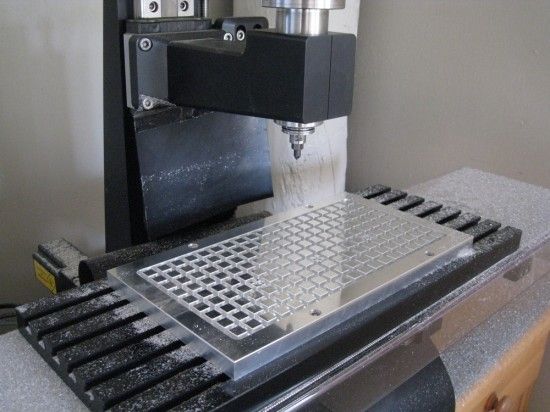
3D printing does not require the manufacture of special tools or tooling, so start-up costs are significantly lower. The cost of a printed part depends only on the amount of material used, the time it took the machine to print it, and post-processing if needed.
+ Inexpensive Prototyping
Prototyping is one of the main applications of 3D printing today. Prototyping is becoming an inexpensive and fast stage in product development thanks to new technology.
Parts printed on a 3D printer are usually ready within a few hours, and on industrial equipment within 5-7 working days.
The speed of prototyping greatly speeds up the design cycle. Products that would require 5-6 months of development can now be ready in as little as 8-10 weeks.
+ Large selection of materials
The most common 3D printing materials used today are plastics. Metal 3D printing is finding an increasing number of industrial applications.
3D printed parts today can have high heat resistance, strength or stiffness, and even be biocompatible.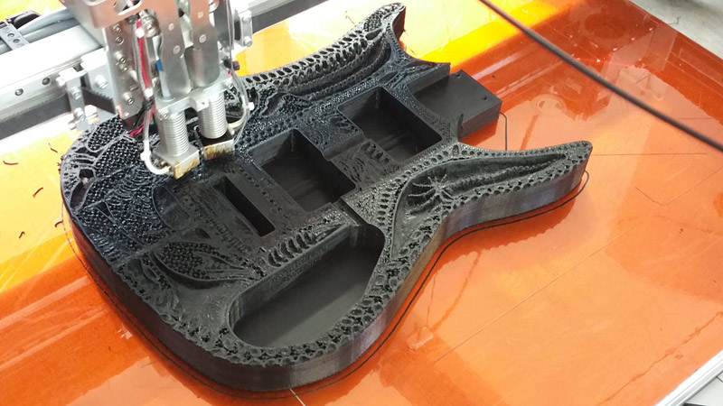
Composite materials used for 3D printing may contain metal, ceramic, wood, or carbon particles. Such materials allow the production of products with unique properties.
Limitations of 3D printing
- Lower strength and anisotropic properties of material
Printed parts most often have physical properties that are not uniformly distributed over the volume: since they are created in layers, the parts are more fragile by about 10-50% along one of the axes. Thus, plastic printed parts are most often used for non-functional applications (to avoid critical loads).
However, technologies such as DMLS allow the production of metal parts with superior mechanical properties. This made it possible to use the technology in areas such as the aerospace and medical industries.
- Not competitive price in mass production
3D printing cannot compete with traditional manufacturing processes when it comes to mass products. The absence of special equipment leads to the fact that the cost of starting production is not high, on the other hand, this leads to the fact that the price per unit of the product decreases slightly with large runs.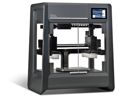
In most cases, the viability of 3D printing is lost when more than 100 units are produced, depending on the material, 3D printing process, and part design.
- Restrictions on precision and manufacturing tolerances
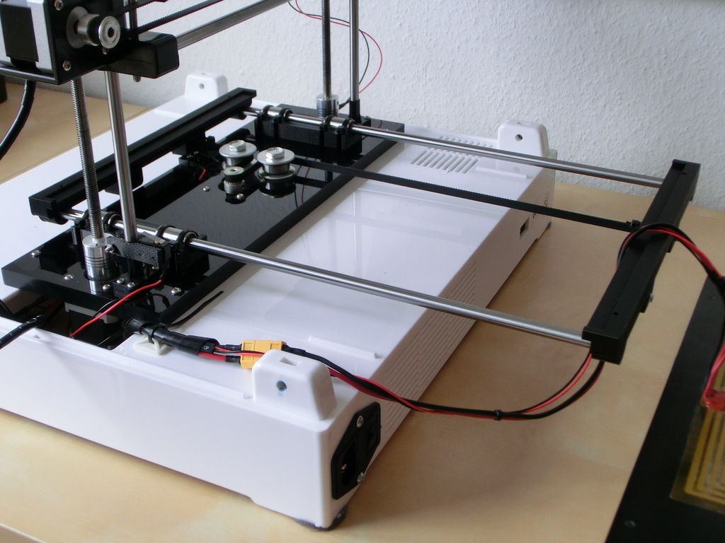
The accuracy of 3D printing depends on the type of printing and printer settings. Generally, parts printed on a desktop FDM 3D printer have the lowest precision and will print with a tolerance of +/- 0.5mm.
Other types of 3D printing offer higher precision. For example, Industrial Material Jetting and SLA printers are capable of producing parts with an accuracy of +/- 0.01 mm.
Metal products printed using DMLS or SLA technology are usually CNC-machined to improve tolerances and surface quality.
- Post-processing and removal support for
Printed parts are rarely ready for use immediately after printing, usually additional post-processing is required.
Building support is required in most 3D printing processes.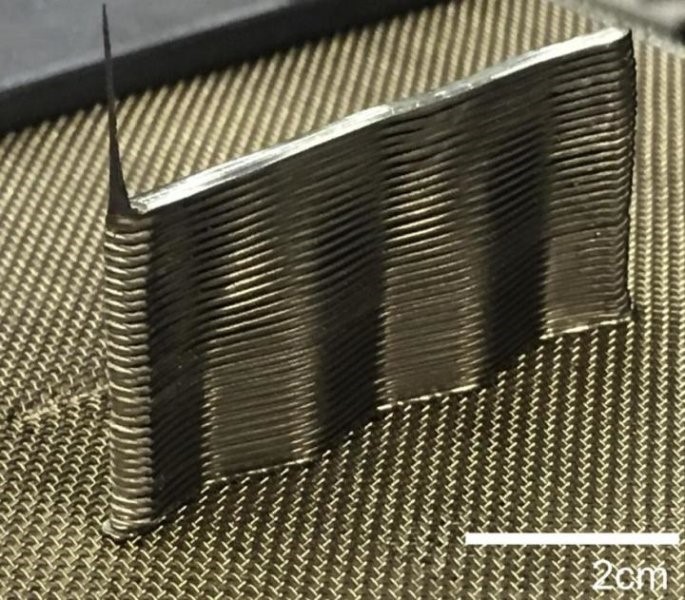 Support is a non-functional, auxiliary part of the product that is printed along with the part. During post-processing, the support is completely removed, but traces may remain where the support material was attached to the part. Such areas require additional operations to achieve a high surface quality (grinding, polishing, painting).
More 3D Printing Related Articles:
3D Printing Technology
3D Printing or CNC Machining
How to Reduce the Cost of 3D Printing
SLS Manual
Metal 3D Printing Gaining Popularity as a Cost-Effective Fabrication Method
Metal 3D printing using pure steel and alloys makes it possible to obtain strong functional parts of mechanical and industrial products.
Any metal 3D printing technology allows you to print with steel. This is the most popular material. But which steel grades and which technology is best for your application? Will printed steel parts really be as strong and durable as traditionally made parts?
Let's see how a 3D printed steel part is revolutionizing manufacturing and opening doors to new applications in aerospace, medical equipment, automotive, tool making, heavy industry, architecture and more.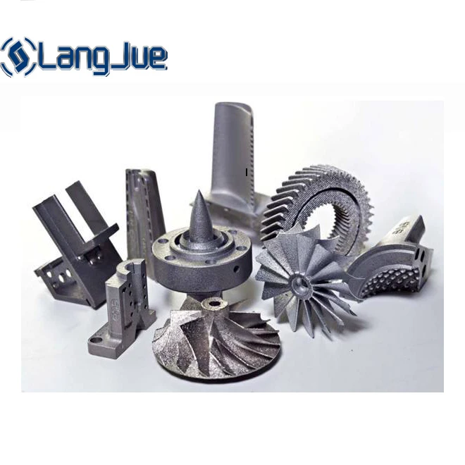 In addition, more affordable desktop printers are expanding the scope and scope of real steel 3D printed parts.
3D PRINT STEEL
Strength of steel printed parts.
The cast steel part (left) compared to the printed version (center) shows the tolerances possible with the technology. Hinge, right, printed as a whole, no assembly required (Source: Desktop Metal)
The most common question when it comes to a 3D printed metal model is "Will it be as strong as a forged or cast part?". The short answer is yes... and no.
3D printed steel parts can be just as strong, and sometimes more durable, than those made in the traditional way. It depends on many factors such as: end use, type of steel, choice of 3D printing method, post-processing and shape of the part. Also, the comparison depends on which of the strength characteristics you focus on: tensile strength, static load strength, fatigue strength, etc.
Parts printed from steel are used in the aerospace industry, for the needs of the military, and also, for example, for the manufacture of a footbridge, shown below. Therefore, the strength of printed products is beyond doubt, but let's take a closer look.
Queen Maxima of the Netherlands officially opens a 3D printed metal bridge. Photo by Adriaande Groot (Source: MX3D)
A steel part printed on a 3D printer using one of the technologies, in particular laser powder sintering (LPBF), has a finer grain structure than cast metal products. This provides better tensile strength characteristics, but in other respects the cast parts are currently still stronger. Most often, LPBF 3D printing is used to replace cast components, but in some cases, 3D printed components can replace forged parts.
One study showed that, under certain conditions, stainless steel parts made using LPBF 3D printers were three times stronger than parts made from the same steel using the traditional method.
In experiments comparing 3D printed steel parts to traditionally manufactured steel parts, researchers create identical parts using two methods and compare their performance. However, head-to-head comparison of details is only part of the big picture.
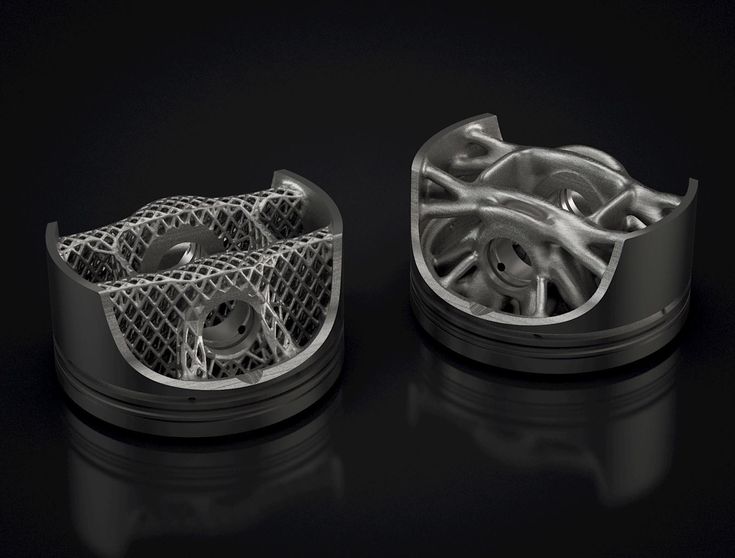
The main advantage of printing with steel is not only its strength, but also the unique ability to create internal channels and lattice fillings in details, which is impossible using traditional manufacturing methods. Metal 3D printing makes it possible to produce parts faster than traditional production, since this method does not require the use of special equipment and tools, it allows you to create assemblies as a whole, eliminating the need for subsequent assembly and welding. Designing a printed part usually means that less metal is needed to make it, and therefore less weight, for the same strength.
Architectural support printed in steel by WAAM by MX3D (Source: MX3D)
3D printing with steel is also a more sustainable and cost-effective practice as it reduces waste. When using subtractive manufacturing methods, such as CNC machining, you make a part by cutting it out of a large one, leaving a lot of waste in the process. With additive manufacturing, you only use the material you need to make the finished product.
Steel 3D printing is not intended to replace traditional methods in all areas, but it can be a better choice for a wide range of applications. Particularly when the required parts are unique and designed for specific applications, such as rocket engines, racing cars or the oil and gas industry. 3D printing is the fastest and most flexible technology for mass production and prototype production. For military and industrial applications, steel 3D printing is a faster and more efficient way to create individual parts for vehicles and machines. Stainless steel 3D printing is rapidly finding applications in medicine to create unique surgical instruments and implants.
If you know what characteristics your final product should have (tensile strength, compressive strength, hardness, density, etc.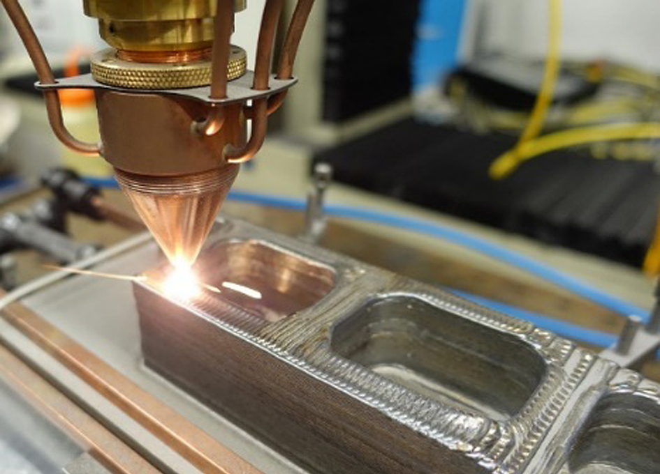 ), then all these parameters can be incorporated into the product at the production stage.
STEEL FOR 3D PRINTING
Types of steel for 3D printing
Metal powder is the most used metal material for 3D printing (Source: GKN Additive)
There are thousands of different grades of steels and alloys with different mechanical properties used in traditional production, but in 3D printing there are only a few dozen, and some of them are unique, created specifically for this technology. Steel options include:
-
Stainless steel (316L, 304L , 17-4PH, 15-5PH, 420, 254, Ph2, GP1, 630, 410)
-
Tool steel (D2, M2, h23, h21, MS1, 1.2709)
-
Low alloy steel (4140)
-
Structural alloyed (20MnCr5)
Recently, unique alloys have been developed specifically for 3D printing, designed to solve the problems that occur when using classical production methods.
For example, 3D printer manufacturer Desktop Metal released a patented stainless steel in 2022 that the company says combines the tensile strength, ductility, and corrosion resistance of 13-8 PH stainless steel with the hardness of low alloy steel. like 4140. The company claims that customers can go to market with parts made of this material and skip the galvanizing step to protect products from corrosion.
ExOne offers two special blends of steel and bronze that the company says allows 3D printed steel parts to have enhanced corrosion resistance while being easy to machine and polish.
While most of the metal powders used in 3D printing are similar to those used for other manufacturing methods, their numbers are on the rise as more companies switch to the technology. Some metal powder manufacturers, such as GKN, also make custom powders for specific 3D printing applications.
HOW TO PRINT STEEL
The strength, properties, and applications of 3D printed steel products largely depend on which 3D printing technology you use.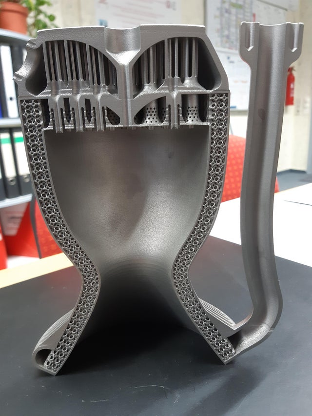 Some methods produce stronger parts, other methods provide better hardness or abrasion resistance, and some technologies are simply very fast.
Below are the main metal 3D printing methods, their properties, and a few of the most common application examples.
Fused Deposition Printing (FDM)
BCN3D's Epsilon printer extrudes stainless steel metal filament (Source: BCN3D)
Fused Deposition Forming (FDM) is a new technology for metal 3D printing, but it is developing rapidly as more printer manufacturers certify metal filaments for use on their printers, e.g. Ultimaker, BCN3D, Makerbot, Raise3D. This method is still much more popular for printing plastics, but with new plastic filaments filled with stainless steel powder, strong metal parts can be produced.
Materials for FDM printing were once limited to thermoplastics. Companies like BASF Forward AM and The Virtual Foundry now offer metal filaments that can be used on almost any FDM printer as long as it has a hardened steel nozzle for abrasive media.
These materials are approximately 80% metal and 20% plastic. After printing, the post-processing process removes the plastic, resulting in 100% metal parts.
Due to the removal of the bonding plastic, FDM metal parts shrink during post-processing. The amount of shrinkage is constant and can be taken into account in CAD systems, which allows to obtain relatively accurate finished parts.
Forward AM's Ultrafuse 316L stainless steel filament produces finished parts with material properties that the company claims are comparable to injection molded metal parts.
(Source: BCN3D)
While 3D printing with metallic materials may not be suitable for applications with tough strength requirements (such as aerospace), the economics of producing simple metal components without critical loads on an affordable FDM printer may outweigh the inability to use them in some applications. .
Ideal use cases for this technology are metal prototype parts and finished parts that will not be subjected to extreme stress.
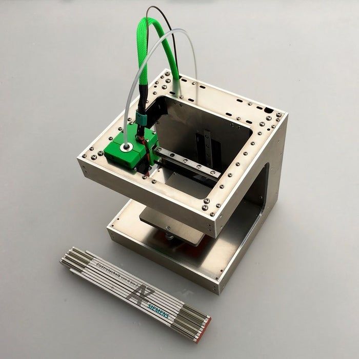
Bound Metal Deposition (BMD)
Desktop Metal's Studio System 3D printer used metal rods connected together and extruded layer by layer to form a metal part (Source: Desktop Metal)
Similar to FDM, metal mesh deposition method (BMD) or bonded powder extrusion (BPE) is an extrusion-based 3D printing process. This method uses bonded metal rods or bonded powdered metal filaments, which consist of a much higher percentage of metal powder than the filaments used in FDM. As with FDM, post-treatment to remove the binder and heat treatment in a final sintering oven are required.
There are only a few 3D printers using this method, such as Desktop Metal, Markforged and more recently 3DGence, but more companies are entering this market, so stay tuned. These printers are valued as a convenient solution for office 3D metal printing, they are more expensive than most FDM printers, but cheaper than the powder-based metal 3D printing technologies described below.
These printers use their own proprietary filament. Desktop Metal and Markforged offer four types of steel.
Ideal niches for using this technology are metal prototype parts, where it is necessary to test the functionality of the part before launching into mass production using traditional methods. Popular applications are moulds, punching dies, nozzles, impellers, fasteners and heat exchangers.
For example, Shukla Medical uses Markforged's Metal X printer to print steel prototypes of its orthopedic implant removal instruments.
Laser powder sintering
Laser powder sintering technology uses one or more lasers to melt powdered metal layer by layer into a desired shape (Source: GE Additive)
Powder material laser sintering (LPBF), also known as selective laser sintering (SLM), is the most common type of metal 3D printing and accounts for 80% of all metal 3D printers on the market.
This method uses powerful lasers to selectively sinter metal powder layer by layer.
LPBF 3D printers come in a wide range of sizes, prices and laser powers. These and other characteristics affect the properties of the finished part, print speed and other parameters of the finished products.
Steel and steel alloys are the most popular material for LPBF equipment and, unlike FDM and BMD, metal powders are commercially available as they are most commonly used in traditional manufacturing methods.
LPBF is a technology that maximizes the quality of a 3D printed part. Applications include aerospace components such as monolithic thrust chambers, rocket engine components and heat exchangers, molds, tools and other applications, as well as high wear parts and surgical instruments.
Binder Jetting
Binder 3D printing technology uses powdered metal and a binder to form metal parts (Sorrce: ExOne)
Ink jet bonding is another powder printing method in which layers of metal powders are bonded using a liquid binder rather than a laser. During post-processing, the binder is removed.
The application of the binder stands out for its high printing speed compared to other 3D printing methods or traditional manufacturing, and the metal parts made with this technology have material properties equivalent to parts made by metal injection molding.
The number of manufacturers producing metal-bonded inkjet 3D printers is much smaller than that of LPBF machines. Leading manufacturers include ExOne, Desktop Metal, Digital Metal, GE Additive and HP.
Ideal applications for bonded metal blasting are medium to high volume production of metal tools and spare parts.
In fact, HP claims that its Metal Jet 3D printer was designed specifically for mass production of 316L stainless steel products. HP has partnered with Parmatech to produce metal parts for the medical industry. Pennsylvania-based ExOne uses this technology to manufacture hard metal cutting tools and tool steels.
Electron Beam Melting (EBM)
(Source: GE Additive)
Electron beam melting (EBM) is another technology for powder cladding material. It works in a similar way to selective laser melting (SLM), but instead of using a laser as the energy source, it uses a much more powerful beam of charged particles.
The recoater moves the powder onto the printing plate, and the electron beam selectively melts each layer of powder. After each layer is printed, the plate is lowered and another one is applied on top of the previous layer.
EBM can be much faster than SLM, but SLM produces smoother, more accurate pieces. The electron beam is wider than the laser beam, so EBM cannot produce the same precise parts as SLM. Another difference is that the manufacturing process takes place in a vacuum chamber, which reduces the amount of impurities in the material that can lead to defects. That is why EBM is often chosen for printing components for the aerospace, automotive, defense, petrochemical and medical implant industries.
Titanium is the most popular metal for most EBM applications, however steel can be used.
Cold Spray
(Source: Impact Innovations)
Cold spray 3D printing technology is carried out by injecting metal powders through the nozzle of a jet device into a supersonic stream of pressurized gases such as air, nitrogen or helium. The process is called "cold" because the metal particles do not melt, but hit the metal substrate and adhere to its surface during the so-called plastic deformation.
Cold spray printed products are not prone to porosity, thermal cracking and other defects associated with melt-based technologies. This method has several advantages over other production methods. It does not require post-processing and usually leaves a small carbon footprint due to the combination of efficient additive manufacturing and the ability to be used in the right place. For these reasons, this technology is used in the military and aerospace industries worldwide.
For example, the US Army uses cold spray to repair the mounts of a worn Bradley 25mm steel turret gun.
In the automotive industry, cold spray steel is used for crash repairs because high-strength steel substrates in automobiles can be susceptible to thermal repair methods such as welding.
Direct Energy Deposition (DED) and Wire Arc Additive Manufacturing (WAAM)
WAAM steel parts from MX3D (Source: MX3D)
Direct energy deposition (DED) uses welding powder or wire that enters through a nozzle and is fed into a power source to melt the metal. A melt region is created and applied to the substrate. DED is a new process, reminiscent of an old building technology known as "cladding", in which a coating is applied to a substrate, often for thermal insulation or weather resistance. DED is useful for manufacturing large objects as a whole, as well as for complex geometries that require extensive machining - DED can get such parts much closer to a finished state than traditional CNC machining.
Since DED uses a coating process, it can be used to create complex geometries in existing steel parts, thus combining complexity with cost reduction. For example, the French company AddUp advertises a rocket nozzle that uses a preformed large 304 stainless steel hopper cone printed with an isogrid structure, usually made from a larger piece by traditional methods.
A technology related to DED is wire-arc additive manufacturing (WAAM). Instead of powder, WAAM uses a metal wire that is melted by an electric arc. The process is controlled by robotic arms. WAAM is also capable of producing large-sized metal parts, as demonstrated by the Dutch company MX3D and its nine thousand-pound 41-foot stainless steel bridge in Amsterdam, as well as an oil and gas equipment repair part, proving that parts can be made in the field.
Micro 3D printing
Micro parts printed from steel (Source: 3D MicroPrint)
Micro-scale additive manufacturing, or micro 3D printing, makes it possible to manufacture products with a resolution of a few microns (or less).