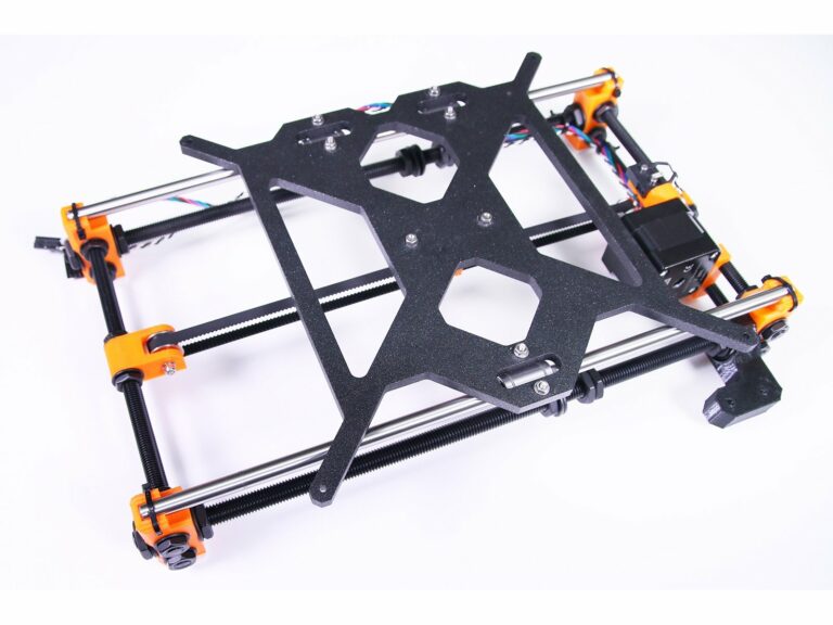
Prusa i3 3d printer assembly
1. Introduction | Prusa Knowledge Base
1. Introduction | Prusa Knowledge BaseEN
- Čeština
- Español
- Italiano
- Deutsch
- Polski
- Français
- 日本語
Login
- Home
- MK3
- Assembly manuals
- Original Prusa i3 MK3 kit assembly
- 1. Introduction
- Original Prusa i3 MK3 kit assembly
- 1. Introduction
- 1. All the required tools are included
- 2. Labels guide
- 3. Use labels for reference
- 4. Spare bag
- 5. View high resolution images
- 6. Printed parts - versioning
- 7. We are here for you!
- Introduction
- 2.
Y-axis assembly
- 3. X-axis assembly
- 4. Z-axis assembly
- 5. E-axis assembly (spiral wrap)
- 5. E-axis assembly (textile sleeve)
- 6. LCD assembly
- 7. Heatbed & PSU assembly (spiral wrap)
- 7. Heatbed & PSU assembly (textile sleeve)
- 8. Electronics assembly (B3/R2 design)
- 8. Electronics assembly (B7/R3 design)
- 9. Preflight check
- Manual changelog
Relevant for
:
MK3
Last updated
a year ago
Difficulty
Very easy
Steps
7
Available languages
Step 1 All the required tools are included
This manual is for the Original Prusa i3 MK3 only! In case you have a new model MK3S+, please proceed according to Original Prusa i3 MK3S+ kit assembly.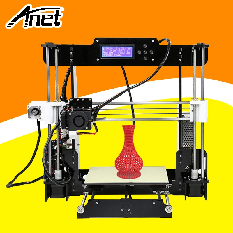
⬢The kit includes:
⬢Needle-nose pliers (1x)
⬢Philips screwdriver (1x)
⬢Allen key (6x)
No soldering is required.
No wire crimping is required.
Step 2 Labels guide
⬢All the boxes and bags including parts for the build are labelled.
⬢Number (or numbers) in the header tells you for which chapter you'll need that bag (or box).
Step 3 Use labels for reference
Most of the labels are scaled 1:1 and can be used to identify the part :-)
Step 4 Spare bag
⬢Every type of fastener is included in a separate special bag.
If you lose a screw when building, use one from this bag.
Step 5 View high resolution images
When you browse the guide on help.prusa3d.com, you can view the original images in high resolution for clarity.
⬢Just hover your cursor over the image and click the Magnifier button ("View original") in the top left corner.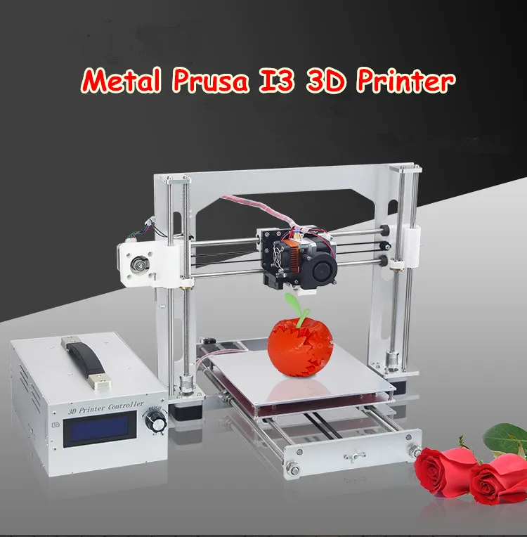
Step 6 Printed parts - versioning
⬢Starting with Original Prusa i3 MK3 most of the printed parts are marked with their version.
In case you have issues while assembling the printer with the certain printed part, please try to find this label and tell it to our support team.
Step 7 We are here for you!
⬢Lost in the instructions, missing screw or cracked printed part? Let us know!
⬢You can contact us using following channels:
⬢Using comments under each step.
⬢Using our 24/7 live chat at shop.prusa3d.com
⬢Writing an email to [email protected]
⬢You can start by assembling Y-axis in the next chapter - 2. Y-axis assembly
Was this guide helpful?
Easy to understand
Solved my problem
Other reason
Comments
Still have questions?
If you have a question about something that isn't covered here, check out our additional resources.
And if that doesn't do the trick, you can send an inquiry to [email protected] or through the button below.
2. Y-axis assembly | Prusa Knowledge Base
EN
- Čeština
- Español
- Italiano
- Deutsch
- Polski
- Français
- 日本語
Login
- Home
- MK3
- Assembly manuals
- Original Prusa i3 MK3 kit assembly
- 2. Y-axis assembly
- Original Prusa i3 MK3 kit assembly
- 1. Introduction
- Introduction
- 2. Y-axis assembly
- 1. Tools necessary for this chapter
- 2.
 YZ frame - preparing the components
 - 3. YZ frame - mounting the longer extrusions
- 4. YZ frame - mounting the shorter extrusions
- 5. YZ frame - final check
- 6. Y-axis: front and rear plate preparation
- 7. Y-axis: front plate assembly
- 8. Y-axis: preparation for PSU
- 9. Y-axis: rear plate assembly
- 10. Y-axis: geometry check
- 11. Mounting antivibration feet (optional)
- 12. Y-axis: front and back holder
- 13. Preparing Y-holder-front and back
- 14. Mounting the Y-holder-front and back
- 15. Preparing Y-belt-idler (part 1)
- 16. Preparing Y-belt-idler (part 2)
- 17. Preparing Y-belt-idler (part 3)
- 18. Mounting the Y-belt-idler
- 19. Y-axis: motor and motor holder
- 20. Preparing Y-motor-holder
- 21. Mounting Y-motor-holder
- 22. Y-axis: Y-carriage
- 23. Correct bearing orientation
- 24. Installing bearings on the Y-carriage (part 1)
- 25. Installing bearings on the Y-carriage (part 2)
- 26.
 Assembling the Y-belt-holder
 - 27. Inserting smooth rods into Y-carriage
- 28. Mounting the Y-carriage
- 29. Securing the Y-carriage
- 30. Aligning the smooth rods
- 31. Assembling the Y-motor pulley
- 32. Y-axis: Assembling the belt (part 1)
- 33. Y-axis: Assembling the belt (part 2)
- 34. Y-axis: Assembling the belt (part 3)
- 35. Aligning the Y-axis belt
- 36. Tensioning the Y-axis belt
- 37. Testing the Y-axis belt
- 38. Y-axis is finished!
- 3. X-axis assembly
- 4. Z-axis assembly
- 5. E-axis assembly (spiral wrap)
- 5. E-axis assembly (textile sleeve)
- 6. LCD assembly
- 7. Heatbed & PSU assembly (spiral wrap)
- 7. Heatbed & PSU assembly (textile sleeve)
- 8. Electronics assembly (B3/R2 design)
- 8. Electronics assembly (B7/R3 design)
- 9. Preflight check
- Manual changelog
Relevant for
:
MK3
Last updated
3 years ago
Difficulty
Easy
Steps
38
Available languages
Step 1 Tools necessary for this chapter
⬢Needle-nose pliers for zip tie trimming.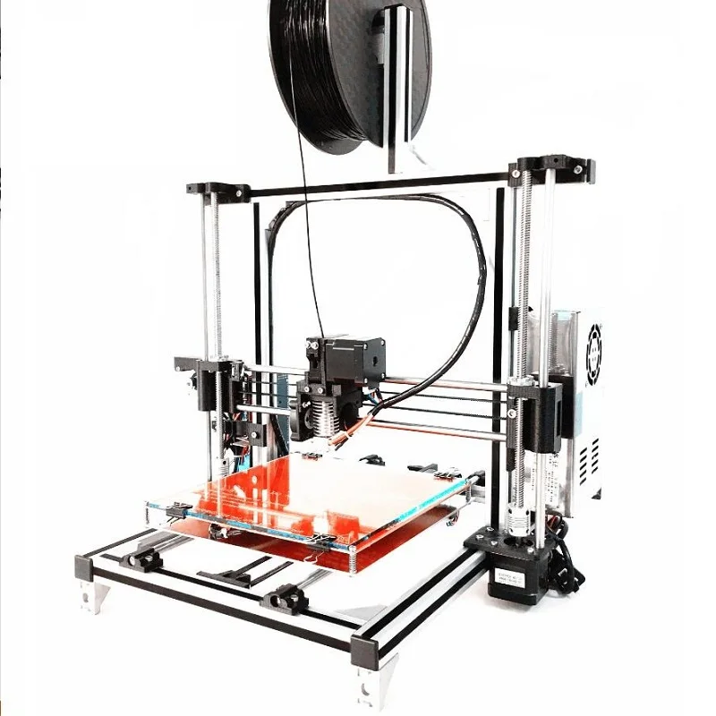
⬢3mm Allen key for M5 screws
⬢2.5mm Allen key for M3 screws
⬢2mm Allen key for nut alignment
Step 2 YZ frame - preparing the components
⬢Prepare following parts to build the YZ frame:
⬢Aluminum extrusions (4x)
⬢Aluminum frame (1x)
⬢M5x16r screw (16x)
You can tighten the M5x16r with included Allen key or with a Torque Wrench. Recommended torque is 4.5 N.m (40 lb-in).
Step 3 YZ frame - mounting the longer extrusions
⬢Take the LONGER aluminum extrusions and place them next to the frame.
Make sure the engraved PRUSA logo on the frame (top left) IS VISIBLE!
Note: screws are inserted from the opposite side of the frame. If you need to manipulate with the frame, make sure the extrusions are on the correct side.
⬢Ensure you are using the correct holes, see the second picture.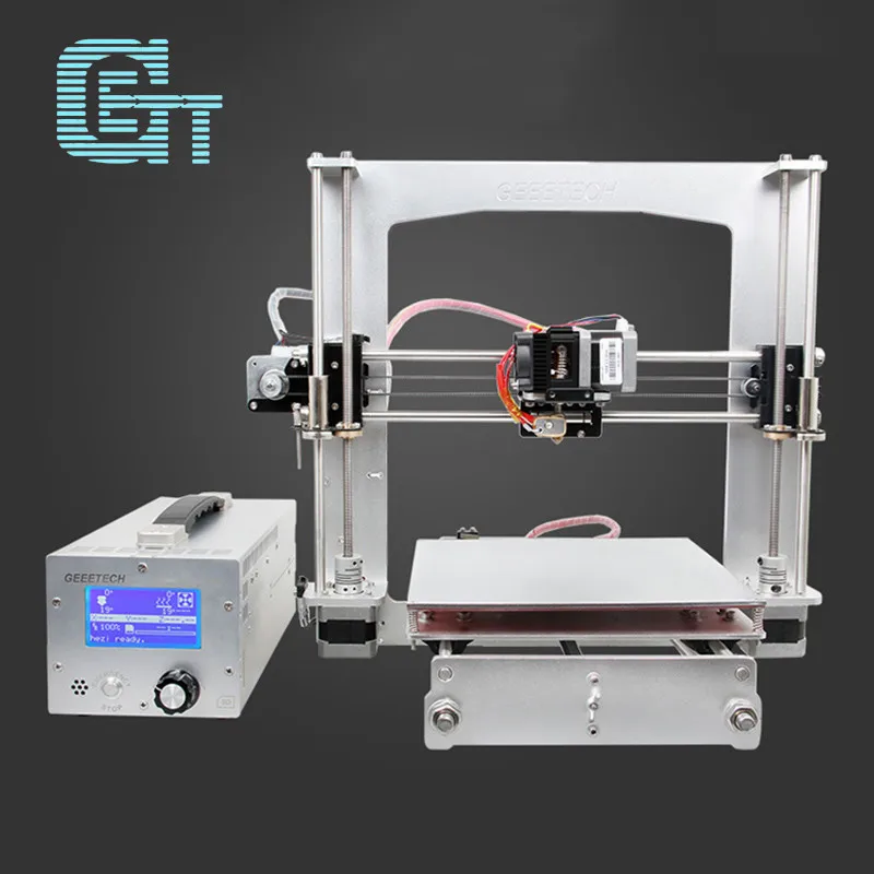 Use the M5 screws to connect extrusions to the frame. Tighten the screws with the Allen key just slightly!
⬢Now, tighten the screws fully, but ON A DIAGONAL, see the last picture. As soon as you finish the first, tighten the second pair. Then proceed to the second long extrusion.
Step 4 YZ frame - mounting the shorter extrusions
⬢Take the SHORTER aluminum extrusions and place them next to the frame.
Short extrusions must be placed on the side, where engraved PRUSA logo on the frame (top left) IS NOT VISIBLE.
Note: screws are inserted from the opposite side of the frame. If you need to manipulate with the frame, make sure the extrusions are on the correct side.
⬢Ensure you are using the correct holes, see the second picture. Use the M5x16 screws to connect extrusions to the frame. Tighten the screws just slightly!
⬢Now, tighten the screws fully, but ON A DIAGONAL, see the last picture. As soon as you finish the first, tighten the second pair. Then proceed to the second short extrusion.
Step 5 YZ frame - final check
Before we proceed further, let's make a final check. IT IS VERY IMPORTANT to have extrusions on the correct side of the frame.
⬢Long extrusions - must be on the side of the frame with the Prusa logo, also ensure longer extrusions are closer together.
⬢Short extrusions - must be on the side of the frame without the Prusa logo, also ensure shorter extrusions are further away from each other.
Step 6 Y-axis: front and rear plate preparation
⬢Prepare following parts to assemble the front and rear plates:
⬢Front plate (1x)
⬢Rear plate (1x)
⬢M5x16r screw (16x)
You can tighten the M5x16r with included Allen key or with a Torque Wrench. Recommended torque is 4.5 N.m (40 lb-in).
Step 7 Y-axis: front plate assembly
⬢Rotate the frame with longer extrusions towards you.
⬢Place the front plate on the extrusions and secure it with M5x16r screws, DON'T TIGHTEN them yet!
⬢Now, tighten the screws fully, but ON A DIAGONAL, see the second picture. As soon as you finish the first, tighten the second pair. Then proceed to the second long extrusion.
Step 8 Y-axis: preparation for PSU
This is a very IMPORTANT step! Incorrect placement of PSU holders will lead to issues later.
⬢For the following step please prepare:
⬢PSU holders M3nE (2x)
⬢Take the YZ frame and rotate it with the shorter extrusions towards you.
⬢Place the PSU holders in the extrusion, ensure it is the correct extrusion. See the picture.
The exact position of the PSU holders doesn't matter, we will adjust them later.
Step 9 Y-axis: rear plate assembly
⬢Ensure the frame with shorter extrusions is rotated towards you.
⬢Place the rear plate on the extrusions and secure it with M5x16r screws, DON'T TIGHTEN them yet!
⬢Now, tighten the screws fully, but ON A DIAGONAL, see the second picture. As soon as you finish the first, tighten the second pair. Then proceed to the second short extrusion.
Step 10 Y-axis: geometry check
Before you proceed further, please place the frame on a FLAT SURFACE (this is crucial).
⬢All the components are cut or drilled by machine for highest precision, but with uneven tightening, it is possible to warp the frame.
⬢Using your hand, try to wiggle with the frame sides and check, whether some corners are lifting up or not.
⬢In case you find some imperfections, release the screws, press the extrusions against the FLAT SURFACE and tighten them again.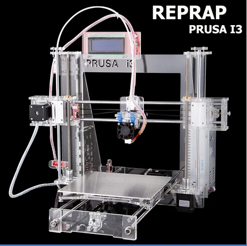
Step 11 Mounting antivibration feet (optional)
Note this step is optional for now. We recommend mounting the feet to protect the surface on your table (workbench). However, you need to lift the frame up before each turn.
There will be extra step at the end of the assembly to remind you of the antivibration feet.
⬢Antivibration feet (4x)
⬢Turn the YZ frame on the side and insert the antivibration foot inclined, then rotate the foot until you squish the rim inside the extrusion.
⬢Repeat this process on all 4 feet. Place them 2-3 cm from the end of each extrusion.
Step 12 Y-axis: front and back holder
ATTENTION: Starting 01/2018 Y-holder-front and Y-holder-back parts are replaced by Y-rod-holder, which has the same shape for all 4 pieces. Please see the second picture. Nut insertion and tightening procedure remains the same.
⬢For the following steps, please prepare:
⬢Y-holder-front (2x)
⬢Y-holder-back (2x)
⬢M3x10 screw (8x)
⬢M3nS nut (8x)
Step 13 Preparing Y-holder-front and back
⬢Take the Y-holder-front and insert M3nS nuts.
⬢Make sure you've pressed the nuts all the way in.
In case you can't press the nuts in, don't use excessive force. First, check if there isn't any obstacle in the nut trap.
⬢Ensure and adjust the alignment of each nut with the 2mm Allen key.
⬢Repeat this step for the remaining Y-holders. At the end, you should have two pairs, front and back.
Step 14 Mounting the Y-holder-front and back
⬢First, take the Y-holder-front parts and place them on the longer extrusions, openings for screws must be facing up.
⬢Rotate the 3D printed parts towards the front plate.
⬢Secure each front holder with two M3x10 screws. Tighten both screws equally, but not completely. We will tighten them fully later on.
⬢Second, take the Y-holder-back parts and secure them with M3x10 screws on the rear plate (with shorter extrusions). Tighten both screws equally, but not completely. We will tighten them fully later on.
Step 15 Preparing Y-belt-idler (part 1)
⬢For the following steps, please prepare:
⬢Y-belt-idler (1x)
⬢M3x18 screw (1x)
⬢M3x10 screw (2x)
⬢M3nN nyloc nut (3x)
⬢623h bearing housing (1x)
Step 16 Preparing Y-belt-idler (part 2)
⬢Take the Y-belt-idler and insert two M3nN nyloc nuts from the top. The rubber inside nuts must be facing up.
⬢Turn the idler to the other side and insert the last M3nN nyloc nut. The rubber inside the nut must be facing towards you.
⬢Make sure all three nuts are all the way in.
In case you can't press the nuts in, don't use excessive force. Take M3 screw thread it from the opposite side of the printed part, as you tighten the screw, it will pull the nut in. Be careful not to break the idler during tightening.
Step 17 Preparing Y-belt-idler (part 3)
⬢Insert the prepared bearing in the Y-belt-idler.
Bearing housing orientation doesn't matter.
⬢Secure the bearing with the M3x18 screw. Don't fully tighten the screw.
⬢Place your finger on the bearing and ensure it can rotate freely. If needed adjust the screw.
Step 18 Mounting the Y-belt-idler
⬢Rotate the frame with longer extrusions towards you.
⬢Take the Y-belt-idler and place it on the front plate. Note there is a mark (circle) on the printed part facing up.
⬢Secure the Y-belt-idler with two M3x10 screws.
DON'T TIGHTEN the screws fully, you will need a "loose" Y-belt-idler to adjust the tension in the belt later on.
Step 19 Y-axis: motor and motor holder
⬢For the following steps, please prepare:
⬢Y-axis motor (1x)
⬢Y-motor-holder (1x)
⬢M3x10 screw (4x)
⬢M3n nut (2x)
Ensure you are using the correct motor, there is a label on the bottom of the casing. The reason is, each motor has different cable length.
Step 20 Preparing Y-motor-holder
⬢Take the Y-motor-holder and insert two M3n nuts.
In case you can't press the nuts in, don't use excessive force. Use an M3 screw from the other side and tighten it.
⬢Place the Y-motor-holder on the motor, ensure the correct orientation as in the picture.
⬢Using two M3x10 screws tighten holder and motor together.
Step 21 Mounting Y-motor-holder
⬢Take the Y-motor-holder and place it on the rear plate (short extrusions).
⬢Ensure correct orientation, the motor shaft must be facing towards PSU holders.
⬢Secure Y-motor-holder with two screws M3x10.
Step 22 Y-axis: Y-carriage
⬢For the following steps, please prepare:
⬢Y-carriage (1x)
⬢Y-belt-holder (1x)
⬢U-bolt (3x)
⬢Linear bearing (3x)
⬢M3nN nyloc nut (6x)
⬢M3x10 screw (2x)
For MK2/S owners, the Y-carriage is now symmetrical in one direction, therefore the dot (countersink, marker) orientation for bearing insertion doesn't matter.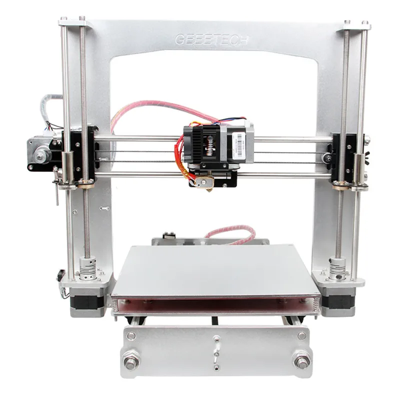
Step 23 Correct bearing orientation
⬢When placing bearings onto the Y-carriage, make sure that they are oriented as shown in the picture. One of the tracks (row of balls) has to be in line with the cutout for the bearing!
This orientation has to be followed in all 3 bearings on the Y-carriage!
Step 24 Installing bearings on the Y-carriage (part 1)
This is VERY IMPORTANT part of the assembly, which can significantly influence printer's behaviour. PLEASE read following lines carefully!
⬢Place the Y-carriage on a flat surface. Orientation doesn't matter.
⬢Insert linear bearing in the cutout and secure it by U-bolt.
⬢Hold thumb on the U-bolt and turn the carriage. Place nyloc nuts on both ends of the U-bolt.
⬢Start tightening the nuts, BUT ENSURE you are tightening both nuts equally and AS SOON AS EACH NUT REACHES THE SURFACE OF THE Y-CARRIAGE STOP TIGHTENING!!! We will finish tightening the nuts in the next step.
⬢Repeat these steps for the remaining two linear bearings.
Over tightening nuts leads to deformation of the bearing and all the issues connected with it. Please follow the instructions.
Step 25 Installing bearings on the Y-carriage (part 2)
Ensure again the nuts are tightened just to the surface and equally.
⬢Check if the bearing is centered in both directions, if not slightly release the nuts and adjust its position. Then retighten the nuts to the previous state.
⬢When you are ready, using pliers rotate each nut, but only 90°. This is enough to fix the bearing without deforming it.
⬢Repeat these steps for remaining two linear bearings.
Step 26 Assembling the Y-belt-holder
⬢Place the Y-belt-holder on the Y-carriage. ENSURE THE TEETH are facing TWO BEARINGS!
⬢Secure the Y-belt-holder with two M3x10 screws. Tighten them fully, there are threads in the Y-carriage.
Step 27 Inserting smooth rods into Y-carriage
⬢Take all the smooth rods and compare their lengths. For Y-carriage you need mid-sized rods (330 mm).
NOW, PLEASE BE VERY CAREFUL! Gently insert the rod straight into the bearings, do not apply too much force and do not tilt the rod!
⬢If you can't slide the smooth rod easily, check the two bearings are aligned properly.
In case you manage to push out balls from the bearings, please count them. One or two balls are ok, if there are more of them, please consider ordering new bearings.
Step 28 Mounting the Y-carriage
⬢Take the Y-carriage including smooth rods and place them in YZ-frame. Make sure, that two bearings are on the left side (see the picture).
⬢Using your thumb, press the smooth rods inside all four holders. Don't use excessive force.
Check again the correct bearing orientation!!!
Step 29 Securing the Y-carriage
⬢Find the package with zip ties and take out 4 pieces.
⬢Slide the zip tie through the holder, there is a slot.
⬢Connect the zip tie and tighten it. The "head" should be inside the frame.
⬢Using pliers cut the remaining part.
⬢Repeat this step in all four corners.
Step 30 Aligning the smooth rods
IMPORTANT: proper alignment of the smooth rods is crucial to reduce noise and overall friction.
⬢Ensure all M3x10 screws on Y-holders are released, so the printed parts are able to move.
⬢Move the Y-carriage back and forth across the entire length of the smooth rods to align them.
⬢Then move the carriage to the front plate and tighten all screws in the front-Y-holders.
⬢Move the Y-carriage to the rear plate and tighten all screws in the back-Y-holders.
Step 31 Assembling the Y-motor pulley
⬢There is a flat part on the motor shaft, rotate it similarly to the first picture.
⬢Place a GT2-16 pulley on the Y-motor shaft as shown in the picture.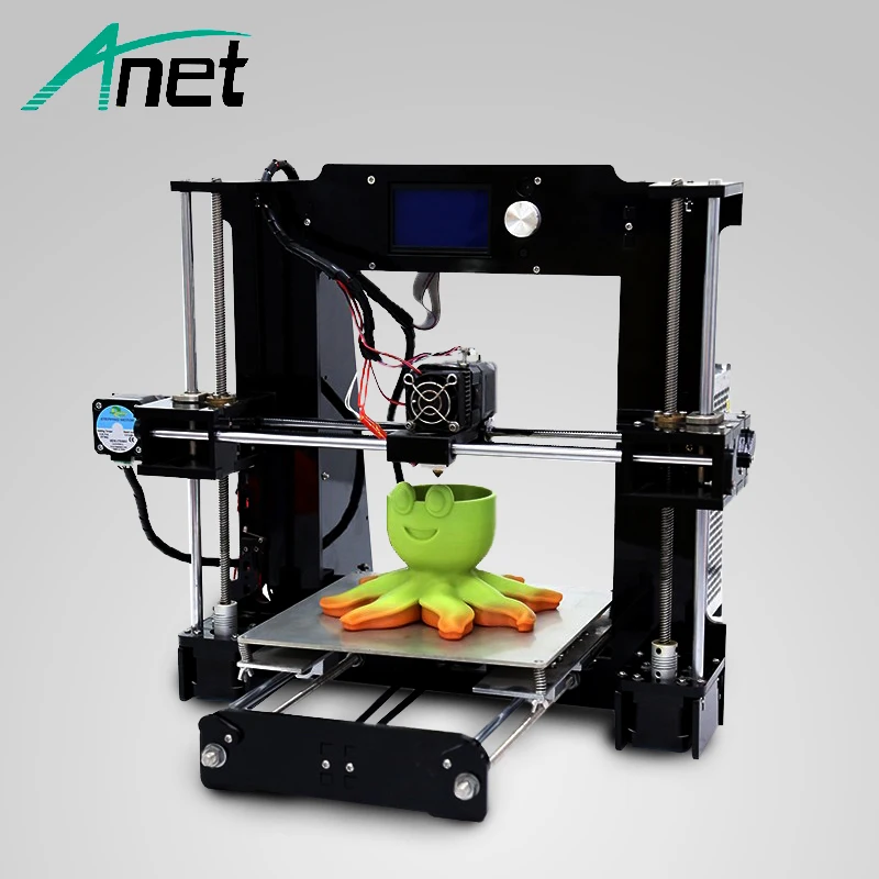
⬢Don't press the pulley against the motor. Leave a gap so the pulley can rotate freely.
⬢One of the screws must be facing directly against the pad (flat part) on the shaft. Slightly tighten the first screw.
⬢Turn the shaft and slightly tighten the second screw.
Don't tighten the pulley firmly yet, we'll get to that later.
Step 32 Y-axis: Assembling the belt (part 1)
⬢Turn the frame on its "right" side, as shown in the picture. You need access to belt holder, idler and pulley.
Use the bottom opening in the extrusion and gently insert the cable from Y-motor.
DON'T TRIM THE BELT unless you are asked in the instructions!!!
⬢Find the belt for Y-axis (Y-GT2 650 mm) and insert one end in the Y-belt-holder. Ensure you are using the upper slot (closer to Y-carriage).
Make sure you won't accidentally use the belt for X-axis (X-GT2), which is longer.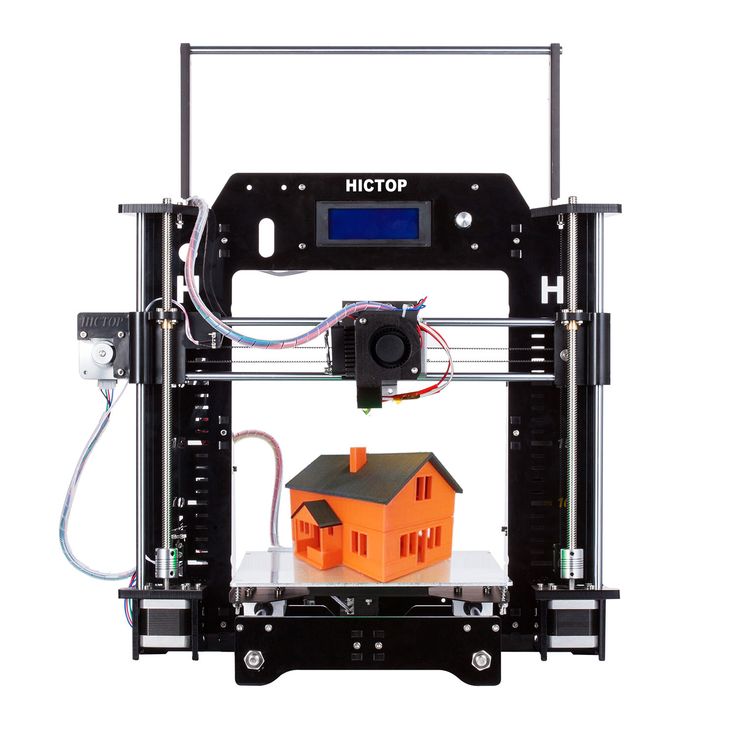
⬢Press the belt all the way in, use Allen key.
Step 33 Y-axis: Assembling the belt (part 2)
⬢Insert the belt through the idler as shown in the picture.
⬢Guide the belt behind Y-axis motor and ensure following:
⬢Don't use the second slot in the Y-belt-holder.
⬢Guide the belt above the aluminum Z frame, NOT below.
⬢Guide the belt above the rear plate, NOT below.
⬢Turn the printer on its "feet" and guide the belt around Y-motor.
Step 34 Y-axis: Assembling the belt (part 3)
⬢Turn the printer back on the side. Hold the Y-carriage by hand (prevent its movement) as we need to pull the belt.
⬢Ensure the idler isn't tightened completely to the front plate. Otherwise, you won't be able to adjust the tension later.
⬢Take the end of the belt, pull the belt with a reasonable force and insert it in the Y-belt-holder. Note you don't have to use the whole length of the slot.
⬢Press the belt all the way in, use Allen key.
The belt should be stretched and not easily bent. However, the final tension will be adjusted later.
Step 35 Aligning the Y-axis belt
⬢Make sure the belt is placed in the "axis" of the printer. Both top and bottom part of the belt should be parallel (above each other).
⬢To adjust the belt position, release screws on the pulley and slightly move with it, until you reach the best position.
⬢In case you can't make the belt parallel, check if the belt is properly inserted in the Y-belt-holder (below Y-carriage).
⬢Tighten both screws on the pulley.
Step 36 Tensioning the Y-axis belt
⬢Using Allen key tighten/release the screws on the front plate. Try to adjust both screws the same way.
⬢Using a finger on your left hand push the belt down. Some force should be needed for bending the belt, BUT don't try to overstretch the belt as you might damage the printer.
Step 37 Testing the Y-axis belt
⬢Use the technique described below to test if the belt is properly stretched.
⬢Use pliers to hold the Y-axis motor shaft.
⬢Move the Y-carriage with your hand towards the Y-axis motor. Don't use excessive force.
⬢If the belt is stretched properly, you should feel a resistance and the Y-carriage won't move at all. If the belt is too loose, it will deform (create a "wave") and jump over the teeth on the pulley.
Step 38 Y-axis is finished!
⬢Y-axis is done, great job! Open the bag with Haribo gummy bears and treat yourself with few ;)
⬢Check the final look, compare it to the picture.
⬢Ready for more? Lets move to 3. X-axis assembly
Was this guide helpful?
Easy to understand
Solved my problem
Other reason
Comments
Still have questions?
If you have a question about something that isn't covered here, check out our additional resources.
And if that doesn't do the trick, you can send an inquiry to [email protected] or through the button below.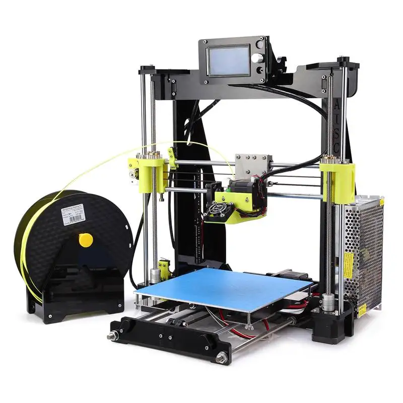
Original Prusa i3 MK2
3D printer reviewSpecifications and features
Prusa i3 is an open source software and mechanical project. And the MK2 model gives us new interesting features.
The MK2 design is a tried and tested solution with a vertical center plate that is the base for the Z and X axes and M12 guide screws. This design allows for a working space of 250 mm wide, 210 mm deep and 200 mm high.
The model is printed on the heated table MK42. This solves most adhesion problems. This table has good rigidity, so you don’t have to invent a bicycle and install some kind of heat-resistant glass surface on top. In addition, the top of the printing table is covered with a thin PEI film. Thanks to this, fingerprints will not remain on it. The table heats up and cools down very quickly. If you're printing with PLA, the platen heats up at about the same speed as the extruder.
In addition, the MK42 table has zones with different heating characteristics. Due to this, such an unpleasant moment as more intense cooling at the corners of the table is compensated (the fact that the table has different temperatures from the edges to the center has a bad effect on printing 3D models from high-temperature plastics with a large contact surface).
The Original Prusa i3 MK2 has an E3D v6.1 all-metal extruder. This means that you can use almost any material for 3D printing: PLA, ABS, PET, nylon, wood-based materials or brass particles. If you want to experiment with carbon, you can put a hardened nozzle. If you need precision, you can install a nozzle with a diameter of 0.25 mm. In fact, the print quality with the original nozzle is excellent, but you can't help but notice how much flexibility the E3D v6.1 gives you.
An inductive sensor is located next to the extruder. In my opinion, such a solution should be implemented in all modern 3D printers. This inductive sensor is easy to set up, operates directly from 5V, takes up very little space.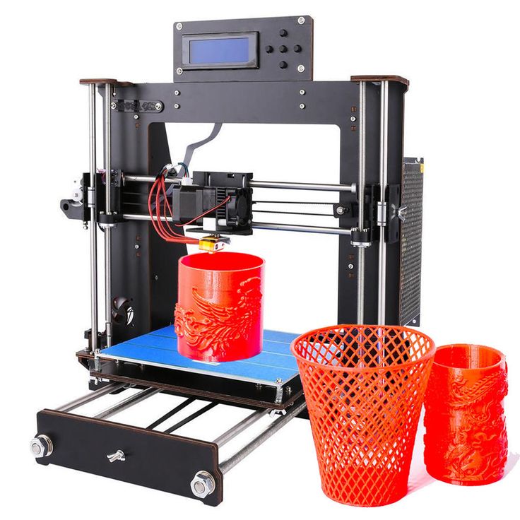
The sensor performs several tasks. First, the virtual mesh of the 3D printing table is corrected. Due to this, even if there are small deformations, they are included in the extruder movement program. Secondly, if you have built the original Prusa i3 MK2, it has special calibration spots on the print table. Thanks to these calibration sections, the X and Y axes are automatically calibrated and small deviations, which are bound to occur during assembly, will also be compensated.
By the way, in many reviews of this 3D printer model, for some reason the last moment is missed. Well, it calibrates itself, and it's great ... But! Automatic calibration technology using calibration squares was not just developed by the Prusa Research team. Since it's open-source, this technique has become part of the Marlin firmware and now anyone can use it!
In most cases, you will interact with the Original Prusa i3 MK2 via an inconspicuous LCD control panel. In our opinion, the handle with the wheel looks amazing! In addition, the handle is very comfortable to use. Yes, this seems to be a trifle, but in fact, it is precisely such trifles in total that make a 3D printer as a whole better and more convenient. And it is the little things that distinguish a quality product from a quality fake.
Using the LCD screen, you can start calibration, feed media. And it won't be running simple scripts. If something goes wrong, such as the heating elements don't respond with the correct signal or the sensor doesn't send a signal at the expected distance, the Original Prusa i3 MK2 will not continue in "self-destruct mode"
During operation, the heating systems are protected by the Ultimachine Mini Rambo . On the opposite side of the frame is a power supply without a cooler. During operation, it is hot to the touch.
It is very convenient that the power supply has a special cover on the side of the connectors. You do not have to worry about connecting individual wires, just connect the power cord to the IEC fuse connector, and the other side of the cable to the Mini Rambo motherboard.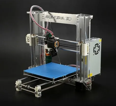 This is amazing! The frame is also grounded using the power supply.
Another interesting innovation concerns wires. Among the wires that go to the extruder and the heated table, 3 mm nylon thread is mixed in, which prevents them from tangling and bending. In our opinion, a very interesting and elegant solution to the problem with wires.
Assembly and print quality
If you decide to assemble the Original Prusa i3 MK2 yourself, you need to set aside five hours. There is a high-quality video of the complete assembly and launch of this model, which was recorded by Thomas Sanladerer (the author of the original English review, by the way). On the video, the assembly took more than 5 hours, but you also had to spend time on entertaining the audience ;).
The manual covers each assembly step, the automatic calibration process. Although the quality of the photographs in the printed version is not the best, you can find the same instructions online. There, the images are stored in excellent quality.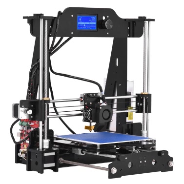
Two 3D printers were ordered for the review. One fully assembled and the second as separate parts for self-assembly. Unfortunately, the assembled printer arrived with minor damage. Apparently, the table latch broke and as a result the LCD case was damaged. I printed the new case myself, but in fact, if such a situation arises, Prusa Reseach will send you a new part under warranty without any problems.
After assembling the Prusa Kit, it turned out that they work exactly the same. In fact, if it weren't for damage in transit and slight differences in frame color, they could only be distinguished by the serial number.
Each printer comes with a test program. And the quality is really amazing!
The dragon pictured below is the first piece printed on the assembled Original Prusa i3 MK2. Printed through a cloud service, without installing software on a PC. There is simply nothing to complain about!
But what's the point of a quality test print? After all, we are counting on excellent printing of our own, not test 3D models.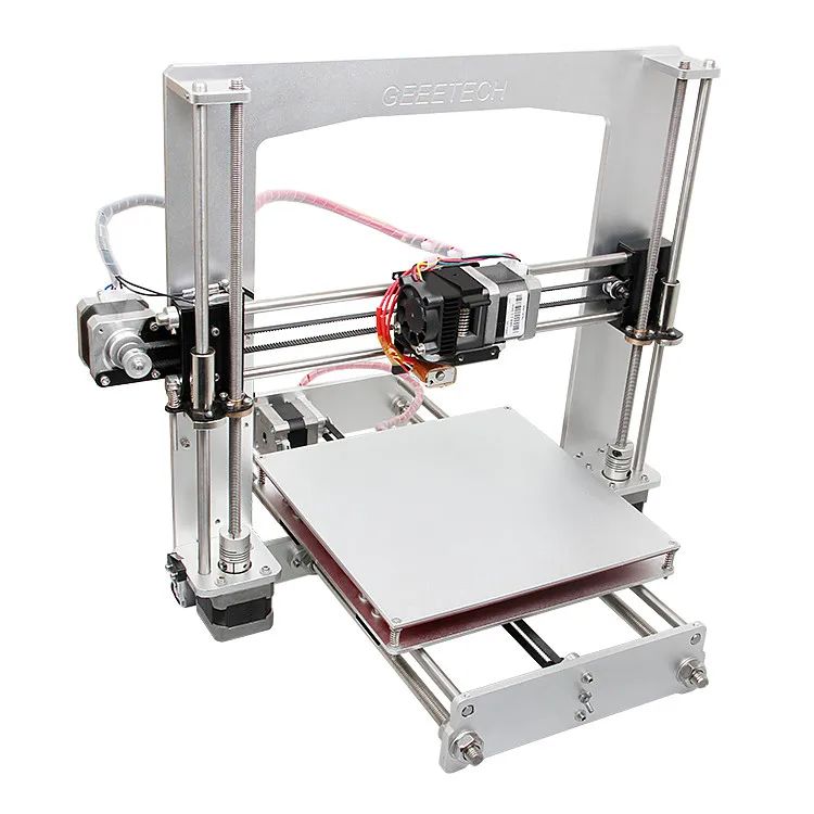 Well, Prusa Research provides all the necessary programs for installation on different operating systems: Windows, Mac OS. If you are using GNU/Linux, there are separate instructions for installing the required packages. The software contains all the necessary drivers, pre-configured slicer, printer host, Netfabb installer, tools for color printing.
I would like to consider drivers separately. When you connect Original Prusa i3 MK2 via USB, it connects via serial port. So you can use it from PC, Raspberry PI, Octoprint or other cloud based 3D printing solution. There is full support for Windows 10 (most likely Windows 8.1 as well), so you can use the integrated Builder app to print directly from professional CAD programs like Solidworks.
This is really cool, and apart from 3D Systems and Stratasys, no other 3D printer provides such a wide range of possibilities. In general, if you become the proud owner of an Original Prusa i3 MK2, you can use any Windows application that supports direct 3D printing.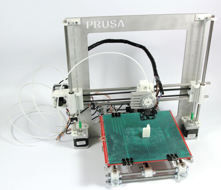 Very, very comfortable.
Naturally, you can use the traditional methods of exporting your model to an STL file and processing it in a slicing software. Slicing software Slic3r with ready-made settings is included. This version has some features and modifications compared to those available for official download.
It has a full profile with settings for a 3D printer, for different layer heights, nozzle sizes and a whole range of 3D printing materials - from standard ones like PLA, ABS, PET to Taulman T-Glase or Bridge Nylon. All the materials we tried to work with gave excellent 3D printing results (if, of course, you choose the right settings).
If you prefer to work with other slicing programs such as Cura or Simplify3D, you can download ready-made profiles with printer settings from the official Prusa website.
In our opinion, the availability of ready-made settings for different slicing programs is a huge plus. After spending half a day or more building a 3D printer, having fun with settings and messing up the first 5-10 models is not the most inspiring thing to do.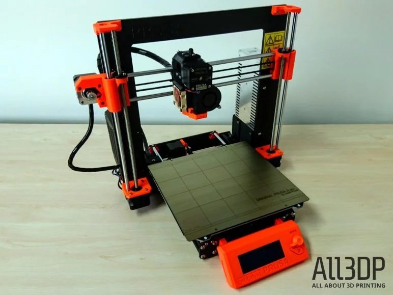 And thanks to ready-made configurations, you can set up your usual software in one click and get excellent quality 3D printing on the Original Prusa i3 MK2.
You will only have to play with the settings if you are using a really unusual material for 3D printing.
Let's now move on to the software part. The software for the Original Prusa i3 MK2 is constantly being improved and if you use Slic3r you will see notifications about the possibility of updating the firmware. After tuning, we were offered some updates that should improve performance, but to be honest, the difference is not noticeable.
One of the coolest features is color printing. Even though the Original Prusa i3 MK2 prints in one color, the development team has included some features to implement color 3D printing (by changing the material in the extruder). You can set up color printing using the LCD controller or by adding G-code coordinates, after reaching which the 3D printer will prompt you to change the material in the extruder.
Original Prusa i3 MK2 - the perfect 3D printer?
Yes, we can say that the testing of the Original Prusa i3 MK2 showed that it is indeed a very good 3D printer. But do not forget that although this is a very successful, but still an ordinary FDM printer, which has certain limitations inherent in the technology of layer-by-layer deposition modeling.
There was an example of bad 3D printing. But in defense, we can say that the model is already complicated and at the same time was reduced relative to the base dimensions. As a result, the transitions were too sharp and you can see the result in the photo below.
While the Original Prusa i3 MK2 is running, you can choose between "power" or "silent" mode. The failed model was printed in quiet mode (this mode is really quiet. The loudest part is the working cooler to cool the model). Perhaps printing in powerful mode would be better. But if you use the powerful mode, being in the same room with a 3D printer is not comfortable. 9The 0005
Original Joseph Prusa i3 MK2 is $845.79 (self-assembled) or $1,087.79 (assembled). Although not the most "advanced" mainstream model, it is in many ways superior to its counterparts and even the most innovative models. At the same time, some fundamentally new and really useful features have been implemented.
Original Prusa i3 MK2 prints great right from the start, without the need for tedious manual adjustments. Probably, this is really one of the highest quality open-source 3D printers today.
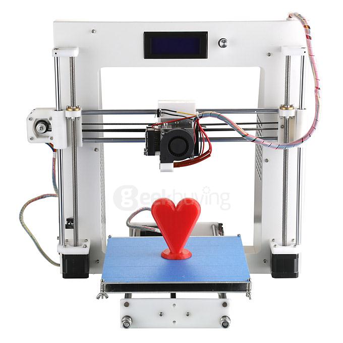
RepRap Prusa i3 3D Printer First Impressions
RepRap is an open and cheap DIY 3D printer project. There are many modifications of RepRap. According to my observations, the Prusa i3 modification is the most popular. As long as it's an open project, you can make and buy all the necessary parts yourself, or buy a ready-made kit for assembly. As you may know from previous posts, I prefer not to worry and buy ready-made kits.
You can buy a Prusa i3 3D printer on AliExpress for around $200.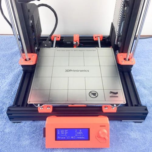 I collected such a printer. If you do not want to wait for a package from China (typically a month or two), the same assembly kit can be purchased from Russian online stores, in particular, Avito. True, this option will cost more.
Assembled 3D printer at work:
Regarding assembly. Despite the fact that the assembly instructions are complete and unambiguous, the assembly is quite complicated. It took me one day off and two weekday evenings. I highly recommend that you first practice on simpler assembly kits, for example, a DIY soldering station from CustomElectronics or a MeArm robotic arm. Keep in mind that you will need a lot of free space to build a 3D printer. I occupied an entire room for this case. Also note that, among others, the printer uses is a very small piece that is surprisingly easy to lose. Believe me, there is nothing fun in crawling on the carpet with a flashlight for half an hour, I checked!
All necessary assembly tools included. However, I'm not a big fan of Allen wrench hexagonal wrenches, so I recommend getting a good set of screwdrivers like this, or even better, a screwdriver, I have a DeWALT DCD700C2 model. Believe it or not, a hammer was also very useful to me when assembling. Soldering is not required to assemble the 3D printer, since all wires are connected using terminals. The only exception is the plug, which turned out to be American, not European. Accordingly, it will either have to be soldered or an adapter purchased. The printer uses 3D printed parts that have both supports and print artifacts. To eliminate them, I used side cutters and a couple of times a mini-drill. Finally, I note that it is proposed to fix the thermal insulation in the lower part of the heating table with a rather narrow PET tape. This tape peeled off very quickly for me, I had to re-glue it with a wider tape.
Regarding printing. Models for 3D printing are distributed in STL format. There are many catalogs of ready-made models - thingiverse. com and others. The model is driven into a slicer program, in which you specify the print options and get a .gcode file. This file is written to an SD card that is inserted into the 3D printer. The printer interprets the GCode, printing the model as a result. It is also possible to print via USB, but this option is fraught with data transfer failures (which happen, I checked) and therefore is not recommended.
There are many slicer programs. I have used Cura. It's open source and runs on everything, including Linux. Appearance of the program (clickable, PNG 1366 x 768, 151 Kb):
Examples of printed models:
SD card. In fact, this is the logo of Ultimaker, which is currently sponsoring the development of Cura. The printer came with a small skein of blue plastic (most likely PLA), with which I printed this keychain. To the right of it, you see the enclosure for the Arduino Nano. Please note that this case is designed for a board without soldered combs.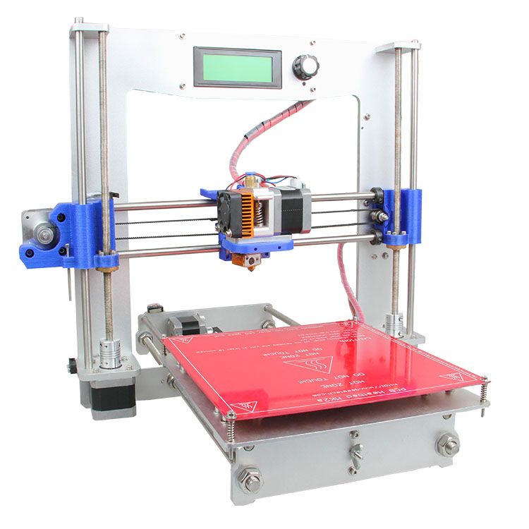
In the background is the case for the Arduino Uno. I modified this model in Blender by cutting holes in the lid for a screen from Nokia 5110 and some control element, for example, an encoder. Blender supports import/export from/to STL, so if you want you can create models using only it. You can find tons of tutorials on using Blender on YouTube. For example, this video shows how to make holes in objects, and this video shows how to work with a mesh and get the model at the correct scale.
Addition: Later I found out that FreeCAD or OpenSCAD is much more suitable for designing new models. These programs are extremely easy to use and learn in just a matter of minutes. In addition, they do not have problems with the scale of the models. An excellent tutorial on both programs can be found on the OpenTechLab YouTube channel hosted by Joel Holdsworth: Prototype Enclosures with FreeCAD & OpenSCAD.
You can see that the last case has a slight squeeze in one corner of both the case itself and the lid. What to do with it is not clear to me yet. The working version that was bought is not the most successful plastic.
Addition: It turned out that such artifacts (folding, warping) occur when printing large enough models with ABS plastic, if a constant temperature of all layers of the model is not maintained. Read about how to deal with this in the post Building a thermal chamber for a 3D printer and printing with ABS. The summary is that it is better to use PLA plastic. When printing with PLA, it doesn't hurt to put something on the 3D printer's table so that the plastic adheres better to it. Lately, I've been applying several coats of hairspray (“Taft is thick and fluffy,” but should work with others). In addition to PLA, consider also PETG plastic. It is a little more difficult to print than PLA, but it is less fragile.
It is worth noting that the RepRap Prusa i3 is far from being the most accurate and, more importantly, far from being the fastest 3D printer in the world.