How to 3d print a city
How to print maps, terrains and landscapes on a 3D printer
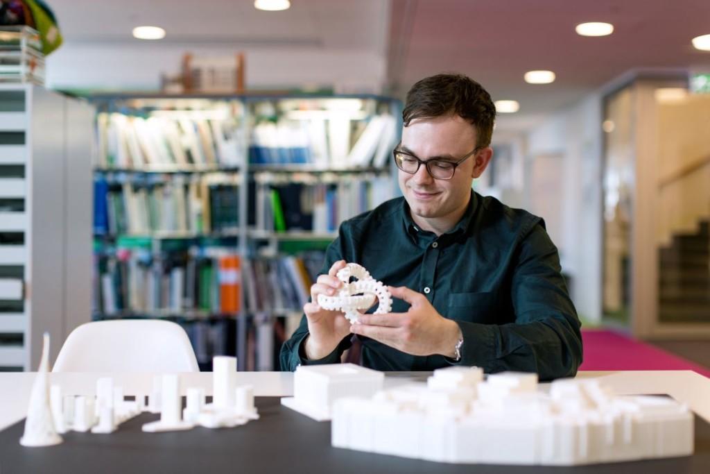
From time to time, every 3D printer owner is asked the same question: “Why is the printer really good and useful? I cannot imagine what would I use it for.” I did not find a satisfactory answer to this simple question at first, because I don’t consider printing figures and statues as the right example. That’s why every time the 3D printing technology is applied in practical use, I’m excited! Today, I’ll show you how to print a 3D map, that can serve in a number of situations not only using our Original Prusa i3 MK3 printer. How about a plastic model of terrain for school education, a small-scale version of a national park, a model that shows the overview of a real-world race track, or perhaps a tiny version of a mountain you climbed in the past. Thanks to these models, we can see the landscape from a bird’s eye view. Input data will be topographic maps that are most interesting for 3D printing purposes.
Models based on maps can be divided into two groups:
- Printing a terrain model – ideal for mountain ranges, volcanoes or abysses.
So where there are well-known elevations.
- Printing a terrain model including buildings – ideal for cities and areas with buildings.
Terrain models
A 3D terrain model (without buildings) can be obtained simply and for free with the Terrain2STL web application.
- Find a place on the map. Rugged terrain works the best.
- On the Location tab, press Center to View. This will show a selection rectangle on the map.
- On the Model Details tab, adjust the size of the selected area by moving the Box Size slider. The selection can be moved in the map. If the resulting model is very flat, it is possible to scale it on the Z axis. This is done in the Model Details by using the Vertical Scaling slider. However, keep in mind that the resulting model will differ from reality.
- On the Water and Base Settings tab, set the desired model base height.
- Press the Generate Model button. Then click the Download button and download the model.
Does a square or rectangular shape feel way too ordinary? Let’s take a look at how to work with some more complex shapes. Naturally, one of the basic ideas is to use borders of existing countries. For the sample print, I chose the Czech Republic – the home of Prusa Research. A good start is to successfully obtain the STL terrain model from the previous step. However, the disadvantage of the Terrain2STL application is that it is not possible to change the shape of the selection. So, if you want to work with a larger area, you will need to cut the STL model first using a 3D editor and then work with it. This is because the Tinkercad software we want to use limits the size of the imported file to 25MB. A better solution is to use a similar tool like Terrain2STL. The TouchTerrain project allows you to select any aspect ratio on the map. I recommend aligning the map, for example, in the upper left corner for a simpler placement of the shape for the cutout.
How to do it:
- Find and download the desired shape in .SVG format. Ideally, it should be on a white or transparent background. To make searching easier, I recommend adding the keyword “silhouette“.
- In a web browser, open the Tinkercad tool and sign in (or create a free account).
- Create a new design by pressing the Create new design button.
- Create a block (use the “Box” tool on the right) and change the dimensions so it stretches across the entire Workplane.
- Import the downloaded .SVG file with the shape using the Import button in the top right corner. When the import is complete, the image is automatically converted to a 3D object. Change the shape type to “Hole“.
- Click the object with the right mouse button and first adjust its height in the Z-axis so that it is higher than the block.
 Then, adjust the size of the model by dragging any corner to fit the block. To keep the aspect ratio hold the Shift key.
 - Now select both objects (Ctrl + A), group them with the Group button (Ctrl + G) and change to the “Hole” type. This creates a negative shape, which then cuts the terrain.
- Import the terrain model using the Import button in the top right corner and wait for it to finish.
- Adjust the size of the terrain model and place it in the right place in relation to the carved shape.
- Deselect the selection of objects by pressing the mouse outside the print area.
- Export the object using the Export button in the top right corner of the .STL format.
- The model is ready to be sliced, for example, in Slic3r, where it can be scaled in the Z-axis if needed for better terrain visualization.
Download link: The Czech Republic 3D terrain model on PrusaPrinters
City model with terrainIn this case, the procedure is a little more complex than the terrain itself and more tools need to be used. To get the model, we use the CADMAPPER web tool, which uses freely available maps from OpenStreetMap as a source. The tool allows you to download a 3D model up to 1 km² area for free. Larger areas are paid. In most cases, 1 km² is perfectly fine. By covering the entire print area (25 x 21 cm), we get the ideal scale for the model (approximately 1: 4000 to 1: 5000).
- Open CADMAPPER tool in the browser and click Create a map.
- Select the desired area up to 1 km² (or larger and buy the model).
- Select the output format for SketchUp 2015+.
- Include Topography and 3D Buildings in the output model and choose the height of buildings for which the height in the map is not defined.
- Press the Create button to start generating.
- Press the Download button to download a generated zip file that contains the .SKP file.
The downloaded file is not yet fully prepared for slicing. What we need to do is to create an object under the terrain. In addition, we can simply change the height of buildings in this tool, especially those that have a default value from CADMAPPER. We will use SketchUp Pro for editing, which is free to download in the trial version.
Eneroth Terrain Volume extension is useful when you want to create a solid object under the terrain easily. Download this extension as well.
Add extensions using the Window -> Extension Manager. Press the Install Extension button and select the downloaded file from the previous step.
Now we have everything ready and we can start editing the model.
- Run SketchUp, open the downloaded file from CADMAPPER (File -> Open).
- On the right side of the application window, expand the Layers section and remove all layers except buildings, topography and Layer0. Press the “Delete content” icon. The content of the deleted layers is not easily printable, that’s why we’re deleting them.
 However, you can play around with the content of deleted layers and see if something interesting comes out of it – we won’t be using them in our guide, though.
 - Click anywhere on the terrain to select it. In the top menu of the app select Extensions menu -> Eneroth Terrain Volume. This creates a solid object under the terrain.
- If you want to change the height of the base or buildings, you must explode the model (select the whole model, right mouse button, Explode option), and then the Push / Pull tool to increase or decrease the height of the buildings or the base under the model.
- Export the model using File -> Export -> 3D Model.
The file is now ready for 3D printing. Open it in the Slic3r PE and adjust the size to fit the print area. For an area of 1 km², the approximately square shape of the model is reduced to about 20% of the original size. So we get the model on a scale of cca 1: 5000. We recommend a PLA material and a layer height 0. 15mm.
15mm.
1:5000
1:2500
1:1000
Download link: Prague Castle area on PrusaPrinters
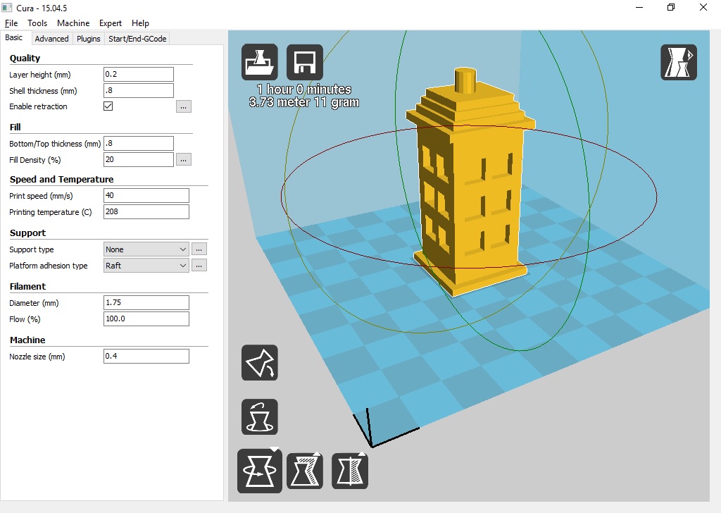
Preparing the model for printing and correct orientationUse Slic3r PE or your favorite slicer tool to generate the gcode file.
Terrain models with at least one straight edge can be printed in two ways, either horizontally or vertically. Each of these orientations has its pros and cons and for each model, it is necessary to decide which orientation to choose. Let’s look at the main differences.
The horizontal positionThis position is natural in the real world. In this position, we are able to print almost any model. In the Z-axis, however, we are limited by the height of the layer. The lowest height of the extruded material is about 0.05mm and the most commonly used nozzle diameter is 0.4mm. The relatively large diameter of the nozzle alone causes “drops” on the peaks. The nozzle diameter also affects edge sharpness.
We recommend selecting a layer height of 0.15mm and a 15% to 20% infill.
Pros:
- you can print almost any model
- there are horizontal lines on the model that represent contour lines (some may consider this a con)
Cons:
- infill is necessary (longer printing time)
- drops on peaks
- there may be strings between the peaks/buildings
In the vertical position, the biggest advantage is that no “drops” of material on the peaks will be created, and the peaks will be smoother. This makes the surface more detailed and looks much better. The vertical orientation is suitable for models where there are no areas that make an angle with the print area less than about 45°. Supports for such models is not a solution we would recommend.
Vertical orientation is also not suitable for printing city-building models, because almost every building would have a perimeter wall parallel to the print surface and therefore the model would be non-printable without supports.
With vertical orientation, it is advisable to choose the most suitable area on which the model will be placed. Choose the one that will touch the bed with the largest possible area. Use the Place on the face button to rotate the model.
We recommend selecting a layer height of 0.15mm and a 0% infill. Infill is not needed in most cases. The printing time will be almost half and you save some material. For best results, use PLA filament.
Pros:
- print without support and infill
- there is no stringing between peaks
- the terrain looks smoother than the horizontal print position
Cons:
- can not be used to print city models
- there’s a chance that it will become loose and that the print will fail
The difference of print in horizontal and vertical orientation is shown in the pictures below.
Our tips for color models:
- Use ColorPrint to change the color of the filament depending on the altitude.
 Learn how to use ColorPrint in this article.
 - Print the model with a single filament and paint it afterward. It depends only on your imagination.
- If you already have Original Prusa Multi Material Upgrade 2.0, you can try to create a color model to distinguish terrain, buildings, waterways and roads.
Feel free to experiment, try various changes and edits, and don’t forget to share the results in our forum.
How to Create 3D Printable Maps Using Touch Mapper
Summary
This blog post will explain how to use Touch Mapper to create maps that can be printed on a 3D printer.
Touch Mapper is a website that enables you to create tactile maps. You can create maps that can be printed on a 3D printer, tactile graphics embosser, or swell paper. This post focuses exclusively on maps that can be 3D printed. It explains how to create and download an STL file that contains a map for a specific address. Loading an STL file into 3D printing software and printing it is beyond the scope of this post.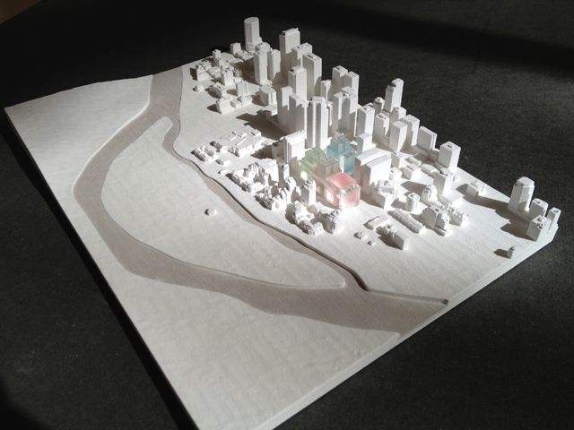
The maps you create using Touch Mapper may contain buildings, roads, sidewalks, and water features such as streams, rivers, and lakes. The objects represented in a map may vary by location based on the contents of the underlying data source which is Open Street Maps.
Touch Mapper supports many options. This is true for most products. Lots of options means lots of flexibility. However, lots of options also creates complexity which can be overwhelming. For example:
- How do I choose between all of the options?
- How can I use the product to solve specific problems?
- If I use the product to solve a specific problem, what options should I use and how should I use them?
Based on my initial experimentation with Touch Mapper, I think it works well for at least one use case that I’ll discuss in this post. I may include additional use cases in the future.
USE Case: Large scale map of a destination
Description
This use case produces a map of a destination such as a building as well as the area immediately surrounding the building. The surrounding area may include roads, intersections, and sidewalks.
Benefits to Map Creator
This use case requires only a few simple options. You do not need to use any advanced options.
Benefits to pedestrians with visual impairments or blindness
The map may enable pedestrians with VIB to create a mental map of the building and the surrounding area. The mental map can be very helpful if the pedestrian is travelling to the destination for the first time or they need to refresh their memory of the destination.
Pedestrians with VIB may be able to discern the following information from the map:
- The approximate size and shape of the building.
- The location of entrances to the building.
- The location of the building in relation to nearby roads and intersections.
- The existence of nearby buildings as well as their size and shape.
- The path of sidewalks that approach the building.
- The location of sidewalks in relation to adjacent roads and intersections.
 For example, is there a sidewalk on both sides of Main Street? Note that sidewalks are higher than roads.
Limitations
The biggest limitation of Touch Mapper is that the map does not include any text or labels. As a result, the map has limited value by itself. Therefore, I recommend that the map creator also creates a written description to accompany the map. Together, the map and a thoughtful written description can enable independent exploration by pedestrians with VIB. See guidance below regarding written descriptions.
Step 1: Create the map
- Go to https://touch-mapper.org/en/.
- Enter the address of the destination in the text field and click Search.
- For printing technology, choose 3D printing.
- For print size, choose the largest size your 3D printer will support. Don’t worry about the price that is listed for each size. It is free to download the map and print it yourself.
- For map scale, choose 1:1800.
:no_upscale()/cdn.vox-cdn.com/uploads/chorus_asset/file/11711015/ib6.0.jpg) See the note below about this item.
See the note below about this item. - Do not check hide buildings.
- Click the Create Tactile Map button. Note that it might take a few minutes for your map to be created.
Note: I recommend the 1:1800 map scale for a few reasons. First, this scale seems to provide enough spacing that it is possible to differentiate features that are close together, e.g. a sidewalk and a road that are parallel to each other. Second, at this scale one inch on the map is equal to 50 yards on earth. That’s a round number that is relatively easy to remember. I also encourage you to teach your students how to estimate distances in using yards because a yard is roughly equal to one step for an adult walking at a normal speed. If you do this, one yard equals one step. Hence, one inch on the map equals 50 steps.
Step 2: Download the STL file
- After the map is created, click the Download the Map Yourself radio button.
- Click the Download Printable STL File link.
 That will initiate the download of the STL file to your browser’s Downloads folder.
Step 3: Print the map
This step is outside the scope of this post. It assumes you have access to a 3D printer and you know how to use 3D printing software. If that is not the case, try to find a local maker space or science teacher that has access. In my experience, most Touch Mapper maps require four to five hours to print. This time may vary widely depending on your 3D printer.
Step 4: Finish the map
Notice the map has no writing on it whatsoever. I recommend that you immediately label the map so you will be able to recall what it shows. If you’re sighted, you can do this by writing on the back of the map. If you’re blind, you can braille the description on a large envelope and store each map in its own envelope. At a minimum, your label should include the address of the destination and the map scale.
Place the printed map on a table in front of you. Notice the map has a raised border on each edge. There should be a raised dot on one corner. That is the Northeast corner of the map. I recommend that you orient the map properly so the North edge of the map actually faces North and you also orient your body so you are facing North. In my experience, this practice reduces confusion.
Notice there is a cone in the center of the map. That cone can be very sharp. I recommend that you use a file to round off the top of the cone to prevent injury.
Finally, write a description of the map for your students. The description must include the name and/or address of the destination building and the map scale. In this case, the map scale should be express in terms the student can easily understand. I also recommend that you use cardinal directions to describe objects in relation to the destination building.
Here’s an example description:
- One inch on the map equals 50 yards on earth.
- The North Carolina Museum of Natural Sciences is in the center of the map.
 The address is 11 West Jones Street, Raleigh, NC.
 - Jones Street is just to the north of the museum. It runs east-west.
- Edenton Street is to the south of the museum. It also runs east-west.
- Salisbury Street is to the west of the museum. It runs north-south. It is a one way street in which traffic flows south.
- Centennial Plaza is immediately to the east of the museum. It is a pedestrian plaza that runs north-south between Jones Street and Edenton Street.
- The main entrance of the museum is on the east side of the museum facing Centennial Plaza.
- Wilmington Street is on the eastern edge of the map. It runs north-south. It is also a one way street in which traffic flows north.
By Ed Summers
SHARE THIS ARTICLE
The largest 3D printed city model / Sudo Null IT News
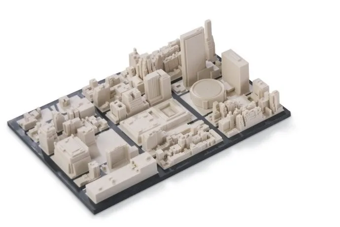
I love cities, 3D models, layouts… A 3D printed city? Perfect! In 2014, the largest printed interactive 3D model of the city was presented in San Francisco, and a year and a half later, this status is still with her. The layout still doesn't cover the whole city, but 115 blocks of northeast San Francisco at 16 micron print resolution and the appropriate level of detail is a really impressive result. I'm surprised no one has posted about this here. I will correct the injustice.
The model was developed by Steelblue, a creative agency engaged in the marketing of large construction projects, under the auspices of Autodesk, commissioned by a large real estate developer, Tishman Speyer. It was made in Autodesk's "creative workshops Pier 9" from VeroWhite photopolymer on two Objet500 Connex 3D printers with a print chamber of 500x400x200 mm. This printer combines a large volume chamber and high print speed with very thin layers, allowing you to quickly and accurately create large parts or even multiple parts in different materials. But even with such equipment, printing took 2 months, 5 days a week, 18 hours a day. The total weight of 68 kg is no joke to you. But there is still a manual post-processing stage, about 45 minutes per quarter.
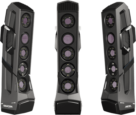
The 3D model was created from a large amount of heterogeneous data. Topographic maps, and three-dimensional scanning, and photographs, and architectural projects from the archive were used. The covered area includes many local attractions that have been recreated with great care. Modeling took about 6 years: from 2008 to 2014. Even the 3D models of buildings available to the developer from previous projects could not be used: at a scale of 1:1250 and printer resolution, it turned out to be easier to build new ones than to simplify the old ones. The minimum detail size corresponds to approximately 30 cm in the real world.
Video of the construction process
The purpose of this large-scale project is to help the developer in urban planning. Any block can be replaced and see what happens. One of the advantages of 3D printing is the ability to easily maintain the relevance of the model. Another advantage is the higher detail, speed of production and low cost than the traditional hand-made layout.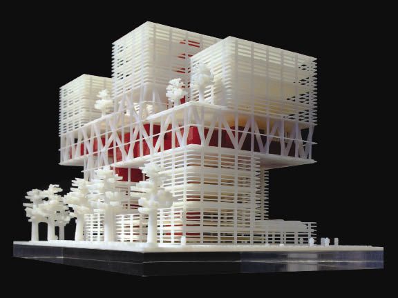 The main point of creating a layout in general is that it allows you to feel the space in a way that an arbitrarily realistic picture on the screen will not help. Although the virtual part of the model also plays an important role: the work is going on in it, and the layout itself is used for presentations.
In addition to the city model itself (in the state of 2017, when some large objects will be completed), the kit includes a projector located under the ceiling, which creates an interactive component for every taste. You can overlay future metro lines or roads on the layout (even simulate the flow of vehicles on them), you can sign the streets or display zoning on some basis. You can simulate the movement of the sun across the sky and follow the shadow zones. Only the limits of imagination limit the ways in which the backlight can be used.
Projector demo
The original with all associated hardware and software remains with the customer, Tishman Speyer. In the copy, which will be shown to the public in the Autodesk gallery, the backlight is planned to be built into the table itself from below, for beauty. Steelblue is ready to expand the model with new quarters, develop a more functional lighting option with several projectors, and would also like to print other cities, but with such a laborious work and a cost of several hundred thousand dollars, the San Francisco layout is still unique in terms of coverage of the territory .
Sources:
Presentation of the layout on the Autodesk website, there is also a report on printing in the Pier 9 workshop
A story by Jeff Mottle, owner of the architectural magazine CGarchitect, about Steelblue's work on this object and future plans
Own The site of the main modeler of this project, Jacob Gubler, also contains similar but smaller prints of Boston and Manhattan, as well as a print of San Francisco made of transparent material Veroclear.
how 3D technology will lead to a cultural revolution - T&P
3D printing methods are now developing so rapidly that what seemed impossible a few years ago is already being embodied in specific technologies.
 Architects are persistently creating an image of a new city life, in which everything can be printed: from women's jewelry to entire blocks.
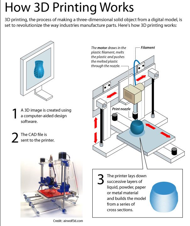
 3D printing is a colloquial name for modern digital additive technologies that are part of a new type of production. To better understand the essence of this method, it is necessary to understand that there are two main ways to produce something. The first is with the help of machining, gradually getting rid of everything superfluous: cutting, beating, drilling. The second one is additive, gradually adding material and building up the required shape.
A year and a half ago, in my predictive study "Elastic City", I tried to imagine how various areas of urban life would change, including manufacturing and the economy with the development of additive technologies. One of the schemes obtained in the work reflects the sequence of changes that occurs and will occur with the transition to 3D printing. It shows how a gradual transition from industrial mass production to individual production in a home or office environment can take place.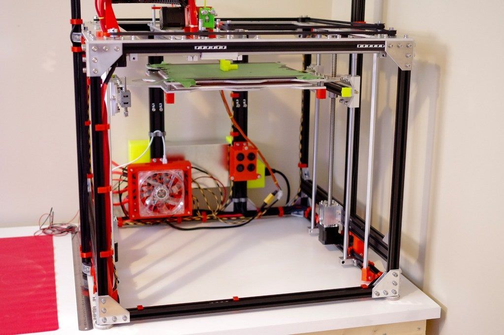 Approximately the same changes humanity observed when office and home printers appeared.
The ability to print products directly at home or in a neighboring office changes the very culture of ownership and eliminates the need to accumulate things.
The ability to print products directly at home or in a neighboring office changes the very culture of ownership and eliminates the need to accumulate things. It will be valuable not to own a thing, but its information model and the ability to print it using some materials that are unique in their properties. Possession of digital information will allow you to reproduce the product again and again at any time. Ultimately, an economic and environmental environment can be formed that will act like a natural biosphere - when an outdated object is immediately recycled to meet new requirements. In this case, it is not the number of products that determine the modern understanding of the standard of living that becomes more important, but the number of alterations associated with the energy spent and depreciation of machines.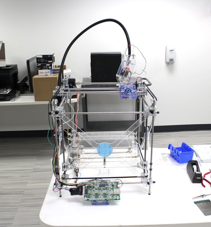
To understand what designers and technologists around the world are trying to develop the ideas of 3D printing, it is worth watching the wonderful animation created for the Full Print3d Printingobjects exhibition held at the Disseny Hub, a hybrid museum and laboratory in Barcelona.
The Economist article titled The Printed World quotes Terry Wahlers, a 3D printing researcher. He says that at the moment more than 20% of the products produced on 3D printers are the final products, and not the prototypes for which the technology was invented. Wohlers predicts that final product production will rise to 50% by 2020.
It can be assumed that growth will be much more intense: this will be associated with the introduction of new methods of production from various kinds of materials and the capture of new areas of industry. For 3D printing technology to be available as an attribute of the home or office, it needs to be cheap, easy to use, and provide something that can't be obtained any other way.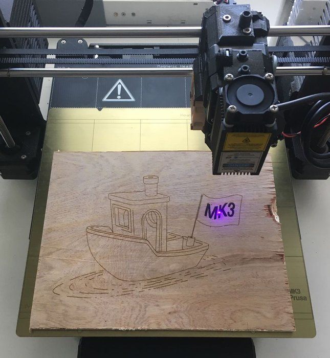 One of the main advantages of 3D printing is the real-time response to needs.
Recently, HP launched a line of their own 3D printers, reflecting the interest of small firms in these technologies - companies are buying machines, despite the hefty price of $17,500. In contrast to such giants as HP and Z Corporation, there are alternative open-source projects like MakerBot or Fab@Home. They make printer assembly kits that start at just $1225.
The European Aerospace and Defense Group (EADS) used an additive layering process that combines 3D printing with laser technology to create the Airbike, a ready-to-ride printed nylon bike. The prototype shows a fully functional vehicle - as good as the one you can buy in a store. Compared to industrial 3D machines, such printers, of course, have a lower quality of product detailing, but they are very versatile in the choice of material. For example, they can be used to print with plastic, silicone, cement, cookie dough, or even cheese. Thus, the field of 3D printing is captured from two sides: global companies and global ideas.
The next direction that takes us into the printed future is connected with the emergence of a studio like Freedom Of Creation (FOC), which was founded by Janne Kittanen 10 years ago in Amsterdam. They were among the first to create their own design, which could not be produced in any other way than additive. “When we started, everyone thought I was a sleepwalker,” says Janne, who is interviewed at least once a month, now. The method of the studio's work is that it gives a design task, and any designer can offer a solution. After that, an agreement will be drawn up for the use of his project, and the product will be translated into reality. 3D printing technology allows you to get rid of the long process of engineering and manufacturing fine-tuning of the product.
A huge step in this direction was the appearance of sites like Shapeways and I.materialise, which allow anyone to upload a three-dimensional file to the site, immediately change the scale of the product and select the material from which it will be made, and then order their product and wait, when it arrives in the mail.
The design studio Nervous System, which specializes in the creation of jewelry, works on a similar principle. The design of jewelry is generated using a computer, and production is carried out using digital technologies, including additive ones.
In the company's online store, you can choose between ready-made solutions and prototypes that can be customized using simple interactive applications. In fact, the buyer receives a unique piece of jewelry printed exclusively for him.
Interior details and furniture is also one of the main uses of 3D printing. It is impossible not to note the pioneers of a new attitude to the creation of furniture - the FRONT studio and their Sketch Furniture concept, created in 2006. It shows a new way of designing furniture: the user draws it directly in the air with a special pen, the trajectory of which is captured using motion capture technology. Next, the digital information is transmitted to the computer, which instructs the printer to print the received objects based on the generated model.
The already mentioned FOC also makes a lot of interior products, but the studio's real breakthrough came when Janne Kittanen created 3D fabric prototypes. The concept of fast-produced textiles was developed back in 1999 by Jiří Ivenhuis. 3D printing has allowed the creation of continuous weaving patterns not possible with traditional textiles.
Printers allow anyone to create their own mechanisms and immediately bring them to life, in connection with which there are applications that simplify the design process. Sneak Peek is a small program for simple modeling of any mechanism for subsequent printing of elements on MakerBot.
But the more interesting property of 3D printing is that it allows
to create mechanisms immediately - without the need to assemble them from separate parts.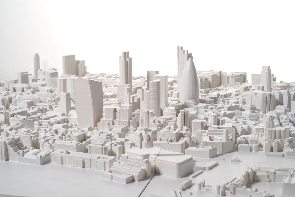 In
In
printed movements, all the parts are already in place and ready to work as soon as the excess raw material is removed. This eliminates the need to invent sophisticated assembly procedures and create couplings that have no analogues in traditional mechanisms. This property is used to create movable prosthetic limbs developed by Bespoke.
Industrial design specialist Scott Summit and orthopedic surgeon Kenneth Trauner of [Bespoke](http://www.bespokeinnovations.com/) have developed a custom prosthetics technology based on rapid prototyping technology using 3D modeling technology. 3D printing has also influenced architecture. For many years architects have been experimenting with scale models using digital manufacturing processes to find form. Fabio Gramazio and Matthias Kohler from the Swiss Federal Institute of Technology examine architectural artifacts built with an industrial robot commonly used to assemble cars and perform various high-precision tasks. Its precision, strength and speed enable them to build architectural forms of unprecedented complexity.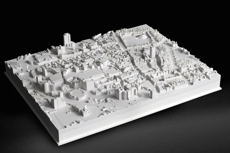
Dr. Behrokh Khoshnevis of the University of Southern California is developing Contour Crafting technology to print entire buildings.
Gramazio and Kohler's work is currently exploring the potential of mobile digital manufacturing techniques that allow one-to-one production of an object right on the construction site. The place of the classic 3D printer here is occupied by a robot: instead of a print head, we see a manipulator that sequentially adds material to the product.
Brick, the most common building material, is becoming the raw material for cutting-edge digital building experiments. The New York Pike Loop project is a 22-meter-long structure built on a construction site by an industrial robot mounted on a movable cargo trailer. More than 7,000 bricks form an endless loop that winds along the pedestrian safety island.
Structure built with an R-O-B robot installed in a movable shipping container. Brought from Switzerland to New York and delivered on a low bed trailer, the R-O-B was transported for on-site production.
New software allows architects to quickly come up with and design structures, but existing building methods do not allow the full potential of the new software to be realized. This makes architects and engineers think about finding new production solutions.
Dr. Behroh Khoshnevis of the University of Southern California is developing a technology that allows entire buildings to be printed. Contour Crafting is a method of layering buildings from ceramic material, which has great potential for automating the construction of entire structures or individual structural elements. Using this technology, you can build each individual house or series of houses according to your own individual project. At the same time, everything can be built automatically in one go - taking into account all the necessary pipelines for electrical wiring, sewerage and ventilation.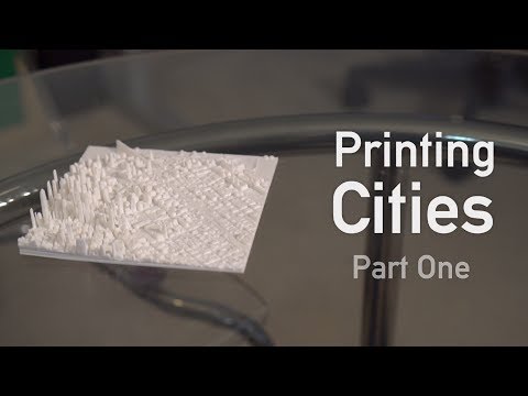
The D-Shape system developed by Enrico Dini can be considered the most innovative in building printing today. This new mechanism makes it possible to create a full-sized sandstone building without human intervention using a stereolithographic printing process that requires only sand and a special inorganic binder. This component transforms sand into a mineral with microcrystalline characteristics, which works in compression and tension much better than Portland cement, which makes it unnecessary to use reinforcement to reinforce structures. Such material is indistinguishable from artificial marble and chemically one hundred percent friendly to the environment.
Despite the higher binder price compared to traditional materials, the final cost of a D-Shape printed structure is 30-50% less than with a manual construction method.
The system is designed to deliver up to four times faster construction time than
traditional building methods.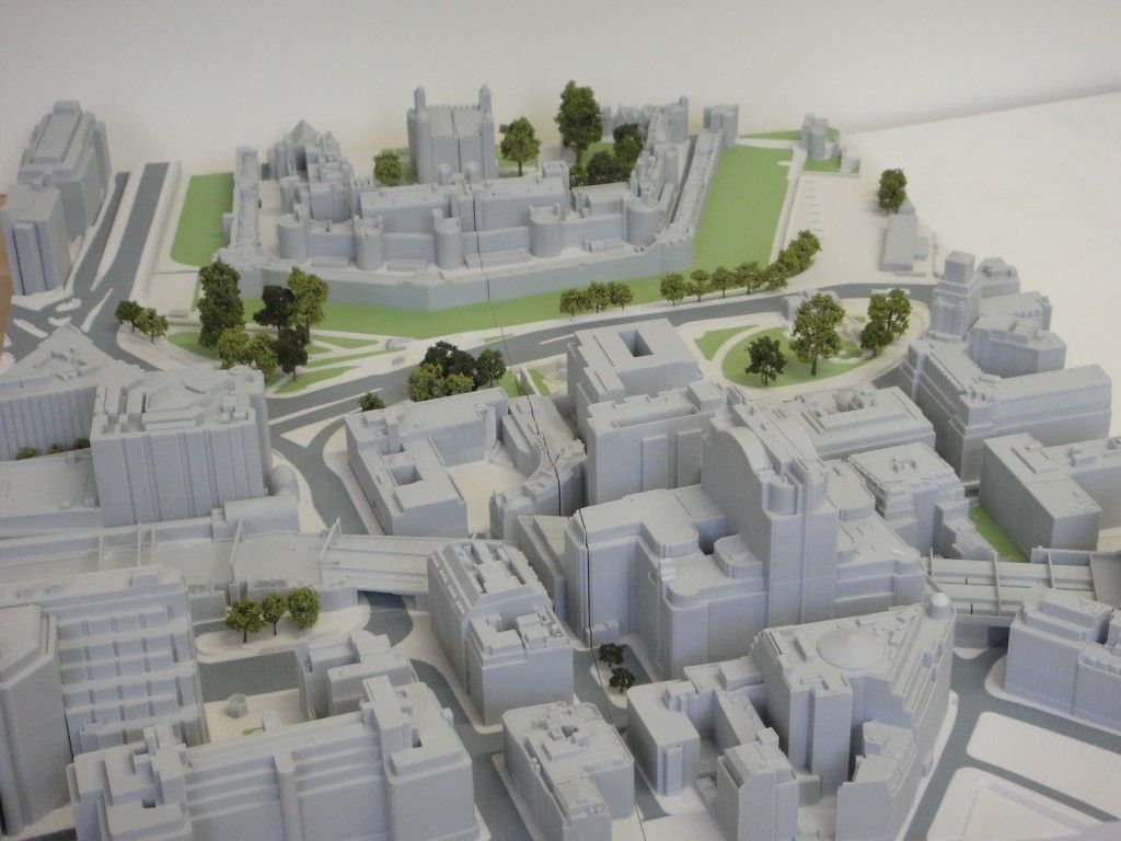 The annual production capacity of the first (small) model machine is 2,500 square meters, equivalent to a 1,220-story building. Despite the higher binder price compared to traditional materials, the final cost of a structure printed with D-Shape is 30-50% less than with a manual construction method. The image shows an element printed by D-Shape that will become part of a villa in Sardinia.
The world's most progressive universities are developing alternative ways to print buildings. At the Architectural Association in London, a group of students are developing an underwater method. Based on the study of the behavior of materials in the logic of digital manufacturing, the Fluid Cast project explores a technology that can help material transition to a different state of aggregation - using water as a catalyst, causing them to solidify. The goal of the project is to develop a digitally controlled building system that will instantly form structures in water. The project also has the potential to reflect on the sea as a development environment that opens up a wide range of possible applications.
There are creative groups that are trying to look far ahead and assess how 3D printing technology will develop in the future. Columbia University's GSAPP School of Architecture has been running the (N)certainties lab for several years running under the direction of François Rocher, one of the most futuristic architects of the modern era.
Intermediaries are no longer needed - it will be cheaper to download the file, adjust the parameters, go to a small company near the house and print the desired item.
The share of energy consumption for transport is one third of the entire structure of the economy. And the share of logistics costs in the price of goods in different countries varies from 10 to 40%. The development of 3D printing technologies is at least a good opportunity to cut costs by removing unnecessary intermediaries.