Ciclop 3d scanner calibration
Calibration — Horus 0.2rc1 documentation
This workbench contains all the scanner calibration processes.
Pattern settings
This section contains the calibration pattern features:
- Pattern rows: number of corner rows in the pattern. Default value 6.
- Pattern columns: number of corner columns in the pattern. Default value 11.
- Square width: default value 13 mm.
- Origin distance: minimum distance between the origin of the pattern (bottom-left corner) and the pattern’s base surface in mm. There is no default value because it depends on the physical pattern.
Autocheck
This section contains the auto check process in which is detected whether the pattern, motor and lasers are configured properly.
The pattern should be placed as shown in the picture. If the process ends successfully, the pattern will be placed perpendicular to the camera. Otherwise, a notification will be displayed.
Laser calibration
In this section, the laser’s planes are calculated. Each plane is defined by a normal vector and the minimum distance from the plane to the optical center of the camera.
To begin the calibration, the pattern must be placed perpendicular to the camera, as shown in the picture. At any time you can cancel the calibration and the pattern will return to its initial position.
Finally the result is shown numerically and depicted in 3D. Also, the dispersion of the captured points during calibration appears. This value must be less than 0.1 mm. You can accept or reject the calibration result.
Platform calibration
In this section, the homogeneous transformation matrix from the rotation center of the turntable with respect to the camera system is calculated. This matrix is composed by a rotation matrix and a traslation vector in mm.
To begin the calibration, the pattern must be placed perpendicular to the camera, as shown in the picture.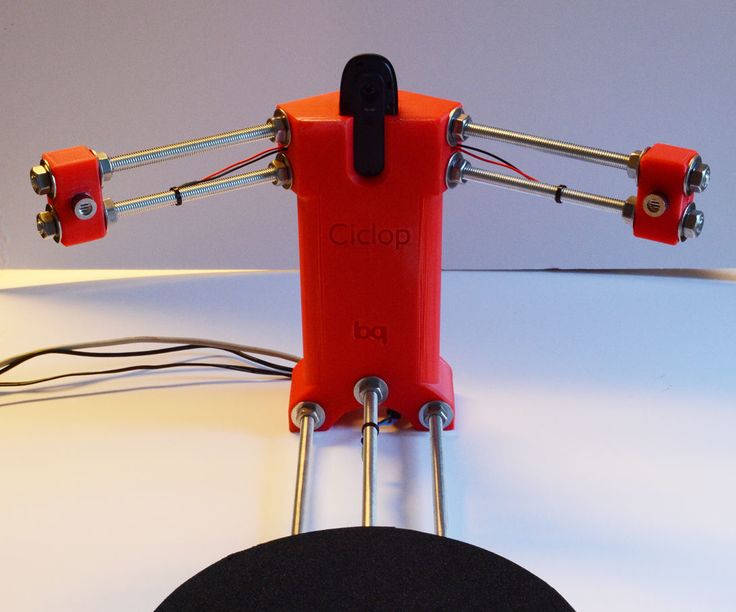 At any time you can cancel the calibration and the pattern will return to its initial position.
Finally the result is shown numerically and depicted in 3D. You can accept or reject the calibration result.
Once this process is completed, the scanner is calibrated.
Video settings (advanced)
This is an advanced section. It contains the rotation flags for the video. Also you can set the camera resolution in px.
Hint
If a wrong resolution is set, the nearest resolution is recommended. Also, you can go back to the latest resolution.
Note
In Mac OS the resolution can not be set in runtime because of its OpenCV version.
Camera calibration (advanced)
This is an advanced section. Default values are recommended.
To begin the calibration, press the “space” key to capture the pattern in different positions. Once taken all the captures, the calibration starts automatically. You can reset the taken captures at any time.
Warning
If camera intrinsics values are modified, laser and platform calibrations must be performed again.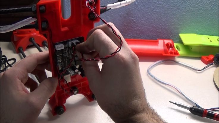
Note
To enable the advanced mode go to the menu View > Advanced mode.
[Review] Scanner 3D - He3D Ciclop 3D - 3D Print
Post Views: 1,061
The Ciclop 3D scanner has revolutionized the world of 3D scanning a little. First of all because it is completely open source, which means that the hardware and software are available to everyone. You can buy or make yourself by purchasing certain components and making the remaining 3D printing. Being a DIY kit makes it, to date, one of the cheapest scanners.
This 3D scanner is designed for anyone who likes to tinker and play with technological objects. The Ciclop purchased by me on Gearbest came after 10 days of waiting and disassembled piece by piece. It took me about an hour to mount the scaner completely. To do this I followed a video guide on the purchase page. I must say that the part of the installation was definitely the easiest. I’m going to talk about it in a little while.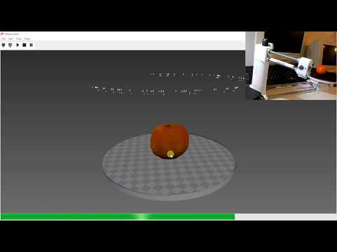 They recommend it for experienced users, but I am firm convinced that 3D scanning with this tool is accessible to everyone. Of course you have to be willing to tinker a bit between software, settings and adjustments.
Maximum scan size: Diameter: 20 cm Height: 20 cm
Scansion time: 10 minutes at resolution (0.45 th per displacement)
Scan accuracy: 0.5 mm
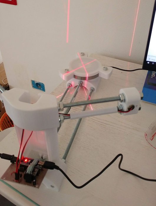
How does the Ciclop 3D scanner work?The Ciclop is a 3D scanner that works for triangulation. It has a webcam in the middle and two lasers, one on the left and one to the right of the camera. Both lasers and the camera focus on a point creating an imaginary triangle. Knowing the angles of the triangle, the distance between the lasers and the camera, the software can calculate the distance between the camera and the red point of the laser, drawing the depth.
The scaner then forms the object on the software, comparing different distances at different points of the objects, rotating them on the scanner platform. To make it faster instead of focusing on a single point, you use a vertical line, scanning many points vertically at the same time.
Cyclop the scanner you can build yourself
The original parts of the scanner can be made with a 3D printer. The manufacturers decided to put all the scanner’s print files on Thingiverse for free. Encouraging people to print the scanner and improve it by putting their own. This is part of the open source philosophy of trying to educate and engage everyone, as a community.
Putting the scanner Ciclop 3D into operationScanner construction:Unlock and build the scanner. This generally takes less than an hour. I recommend the demonstration videos you find on the Gearbest website.
Install drivers:This part can be more difficult than expected. USB drivers are not readily available and right away, without the correct ones it may seem not to work.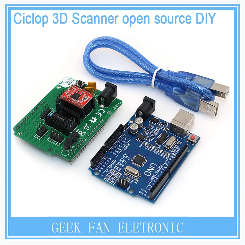 The Logitech C 270 HD will be used for webcamdrivers. After these also those for the Arduino One, the brain of the scaner. Installs together with the Arduino IDE.
Horus is their free software. With Horus you can calibrate the scanner and get your scans in a point cloud format. Here’s the Horus download link.
Calibration of Ciclop 3D:
This step is very important for accurate scans. First you have to place the cardboard, the paper chessboard on the rotating platform as indicated by the wizard. Once finished then you have to select the calibration screen and start the advanced calibration of camera, laser and footer.
Configure settings:Configuring settings such as brightness and contrast is important for best results. There are many settings with which you can play before scanning. Optimal settings vary from scan to scan. Having good lighting is the basis for getting to have good results.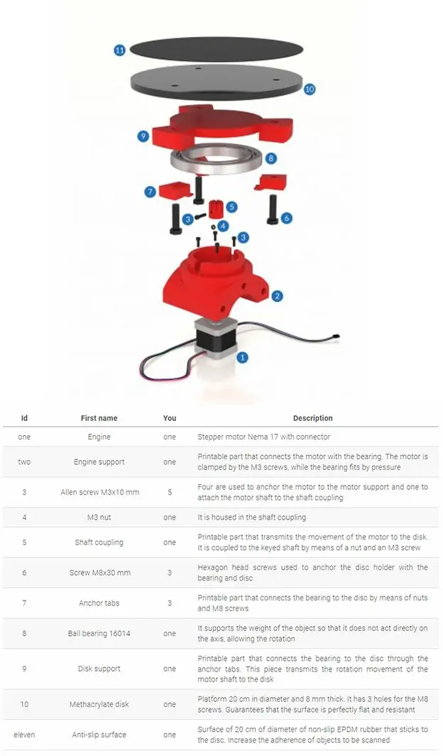
You now place the object in the rotating platform and expect the scanning process to be complete. The scanning process typically takes about 10 minutes at maximum quality, half at medium and still half low. I do not recommend using the low resolution because a decent resolution is not reached.
Convert a file to STL:
After scanning your object, you will have a .ply file. Then you can open the .ply file with a free program like meshlab and convert it to an STL file. The reason you should turn the file into an STL format is that the 3D printer can read and print the file.
Print: Now that your scan is in STL format you are ready to print!
Factors influencing scan qualityThere are a couple of factors to take seriously before scanning that affect quality more than we imagine. The first is the light with which the platform lights up, make sure there are no shadows.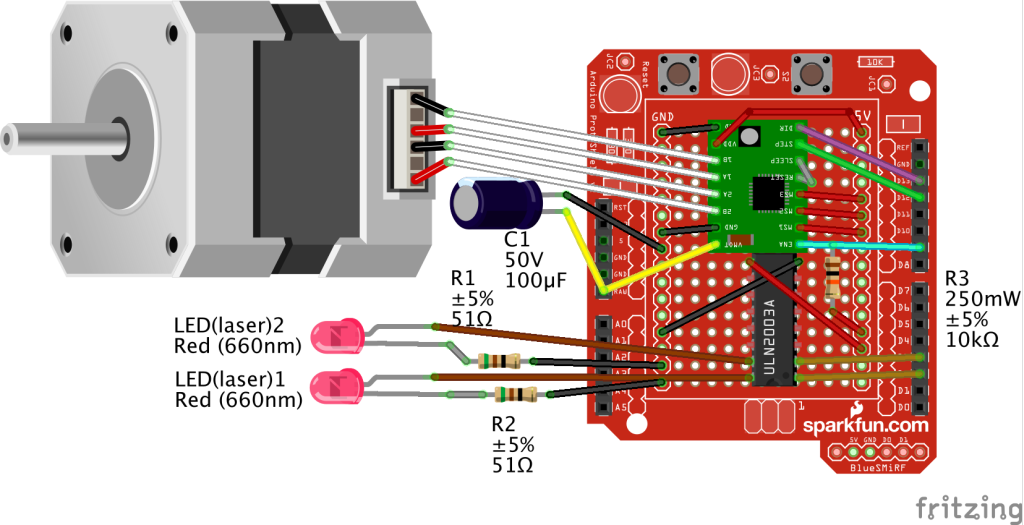 Another factor may be the surface sheer of the object. If the object is shiny or reflective, it will be difficult for the camera to properly scan because the laser will be reflected on the object.
The third and last important factor is the color of the object. Red objects can cause a problem because being the same color as the laser could interfere with scanning. Mirrored objects in a very bright environment can also be a problem. Svi found in this condition and in this case you can reduce the brightness in the settings. Finally, the dark colors do not fully reflect the red laser, so it is advisable to adjust the contrast to improve the quality of the scan.
Conclusions about Ciclop 3DThis is a very practical scanner and one of the cheapest on the market. It’s a do-it-yourself kit. Because it’s an open source scanner, hardware and software are always improved by both the company and the hobbyists who contribute as they can. I would recommend it to those who like to tinker with technology.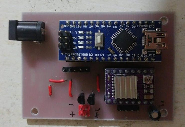 If you are tech savvy, this scanner can be very inspiring.
The scanner can be purchased for as little as USD 109. on Gearbest,the best market price.
If you have found this post useful, please LIKE on Easy 3D Home Facebook’s page to receive updates on all the news of the Blog! You can find other post about 3D Print in 3D Printing section!
Like this:
Like Loading...
3D scanners Ciclop and Piclop
3D modeling
Subscribe to the author
Subscribe
Don't want
19
Two scanners with a similar ideology, but different hardware and software solutions. Probably the easiest way to scan a model is to place it on a turntable, illuminate it at an angle with a laser pointer with a cylindrical lens that turns a point into a vertical line, film it with a camera, and calculate the offset of the line points from the vertical caused by the model.
About 3 years ago the idea was implemented in Spain by BQ labs and published under free licenses. Details of the design for printing on a 3D printer and a very beautiful horus program written in Python were posted. To clearly highlight the laser illumination, it was necessary to control the exposure of the camera. At the time of creation, Ubuntu 14.04 was up-to-date. V4L2 supports camera control, but it does not interface with the official version of OpenCV.
Following the principle of writing minimal custom code to get a workable result, the developers slightly tweaked the current version of OpenCV. The decision is correct, a working installation has been received, and whoever is late, let him clear up the situation in which installation on new versions of Ubuntu requires the demolition of all programs using newer versions of OpenCV. Ideologically, the system is outdated, and the authors. it was probably not interesting to edit subsequent versions, especially since this did not affect the mass consumer using Windows in their work, since this OS uses drivers from the camera manufacturer.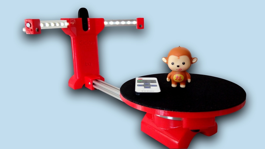
The community, of course, tried to solve the problem, but it seems that they did not achieve an ideal result that suits everyone. I followed the solutions suggested by Fabien Devaux. Its horus version does not require a special version of OpenCV, but is very slow. He proposed his own solution to this problem by writing a program thot with a CLI (Command line interface) command line interface. The program has its own automatic calibration system, but you can also use the calibration results obtained using horus.
I really liked the program, but automatic calibration is not my style :-). In the case of manual calibration, achieving a result is a matter of time and patience, and in the case of automatic calibration, it is always a lottery. The Ciclop design is not well suited for calibration by moving the lasers and camera, although it is of course possible to tweak the automatically generated numbers to obtain an acceptable result with the existing arrangement of the design elements.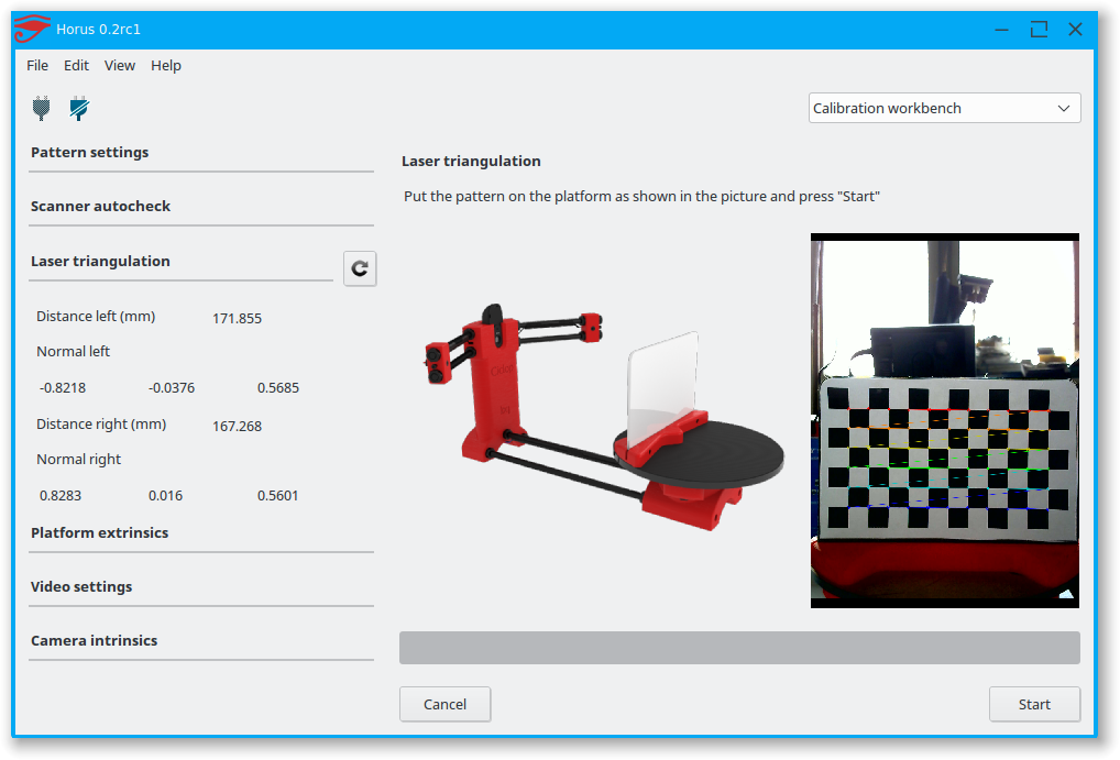
Therefore, having met on the net a description of the scanner on the Raspberry Pi camera (with which I am well acquainted) and requiring precise mechanical alignment of structural elements, I decided to repeat it. In this case, the freelss program, written in C ++, is used for control. Raspberry Pi cameras have very rich exposure controls, but this program does not use them, and uses adjustable lighting for fine adjustment.
At this stage, I did not change the program and decided to compare the capabilities of the scanners as if in their original form. Since I assembled my design exclusively from the available parts, some changes were made to the design, and compatibility with the source code of the program was achieved by introducing, generally speaking, an extra element on the Arduino computer.
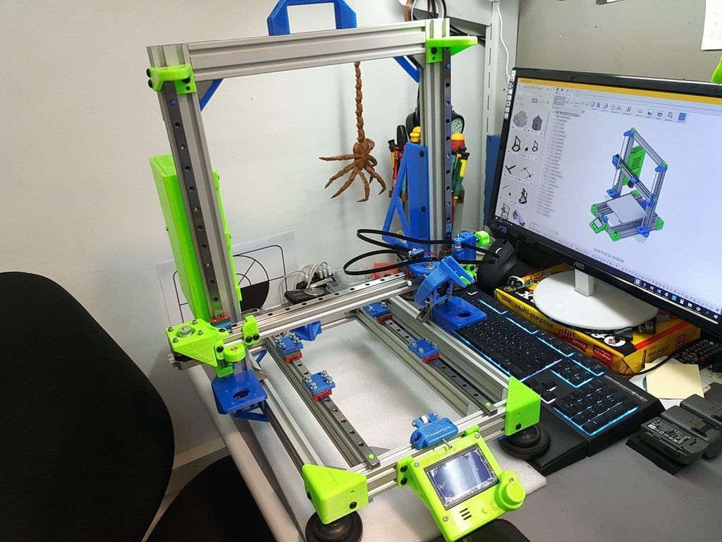
- My Piclop scanner design
- Scanning with freelss
- Scanning with horus
- Scanning with thot
- Processing
- MeshLab
- CloudCompare
- Summing up
Scanners achieve approximately the same result.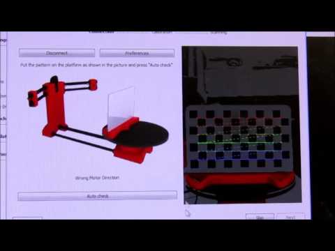 The high resolution of the Piclop camera is not in demand, as is the ability to take more than 800 shots in one revolution. The perceived thickness of the laser beam limits the resolution. The perceived thickness of the line depends on the brightness of the point, which in turn depends on the reflectivity of the material of the model and the angle of incidence of the beam on the surface.
With the current laser beam extraction algorithm, reducing the line thickness due to better focusing or increasing the single threshold value will result in improved resolution for bright points and complete loss of information for darker ones.
Now we have a compromise that by limiting the resolution we get information about all points of the surface on which the laser beam fell. Potentially, for the Piclop scanner, you can write a program that, at high resolutions, will take several pictures with different exposures. However, this will increase the already not small scanning time with a resolution of 5 megapixels.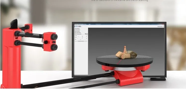
Aside from individual models with fine, subtle relief, a reasonable resolution for this scanner is 1.9 MP (1600 x 1200). At this resolution, the scanning speed for both scanners is about five minutes, but given the fewer final processing operations, the result from the Piclop scanner will be obtained a little faster.
I found it easier to achieve acceptable results when scanning with two lasers on on a manually calibrated Piclop scanner. This is quite laborious, but patience and time allow you to achieve a result, while automatic calibration is a lottery, you may get lucky right away, you may never be lucky.
Subscribe to the author
Subscribe
Don't want
19
assembling a Cyclops with your own hands and working with a laser scanning program
Greetings to all. Today is a small review of the Ciclop desktop scanner.
Once again, the store offered to take something for review.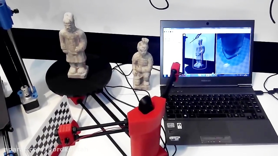 Since I have long been interested in the question of using this thing for the needs of decorative 3d printing, I chose a scanner.
So, the scanner itself was developed by the Spanish company BQ, which has now stopped supporting it (allegedly due to Chinese fakes, but it is doubtful. Now the American CowTech also sells this scanner. The source codes for 3d printing of parts of the scanner are freely available at Thingiverse (there are also links to software and electronics).0003
Links to full documentation sets:
www.cowtechengineering.com/downloads
www.bq.com/ru/support/ciclop/support-sheet
In the kit we have such a “loose”:
The assembly is simple, however there are a few points:
1. It is not worth rushing to tighten all the nuts - you still have to adjust the geometric dimensions - the convergence of lasers in the center of the site, the distance to the turntable.
2. In my stand, the camera “dangled” a little, by a fraction of a millimeter - but that was enough to skew the picture. Eliminated by laying foam material.
4. The turntable was transparent and uncoated (as in the original) - I painted it with plastidip.
5. Check the calibration checkerboard patterns. I don’t know how they printed the one from my kit - but the proportions of the squares were violated. I took it from the Internet and reprinted it myself.
6. The focus of the camera is not adjusted to the distance to the platform. He removed the cover and twisted the focus in place.
88. The economy is managed by the "native" Horus software from BQ.
After assembly, the scanner went through calibration procedures in the native Horus software.
Since by this point I already knew that the quality of scanning is very much dependent on the quality of lighting (stability, diffuseness, color temperature), I took care of having a small lightbox in advance in order to at least provide more or less comparable conditions for samples.
Having selected the "candidates" for the samples, I got ready.
Requirements for the object are stated as follows:
1. The object must be larger than 5x5 cm but smaller than 20x20 cm
2. The object must be opaque and still
3. The object must weigh no more than 3 kg
Difficult to scan:
1. Shiny, luminous objects
2. Too dark objects
3. Objects with a blurred surface (eg soft toys)
The result of the scan is a cloud of points in PLY format (which must then be converted to a surface). Here is a guide for post-processing the cloud and preparing the STL file.
After reading the scan optimization guide, I decided to try with a simple cylindrical object.
After several attempts, I was convinced that I had a common problem - mismatches in the point clouds from the right and left lasers, and the issue with proportions.
We couldn't find anything worthwhile about this except for an attempt to calibrate the webcam settings (they are not calibrated when the calibration wizard is running) (a dude named Jesus from BQ support has not answered questions for a long time). To do this, you need to take several shots with different positions of the calibration table. Done. The situation has improved, but not completely.
I had to manually edit the calibration file (calibration.json in the Horus-a folder) and by trial and error, scanning a cylindrical object, to achieve the coincidence of the clouds.
And everything seems to be ok:
But no - on complex objects, cloud fragments still sometimes do not coincide, moreover, many "blind" zones are formed:
impossible, at least with regular lasers.
You can, of course, continue experimenting with scanning with individual lasers and trying to combine all this economy in third-party software, and then try to bring it into a viable form for STL.
All this is reminiscent of a joke about boats in bottles.
-How do you make boats in bottles?
-I put sand, silicate glue, sticks into the bottle and shake it.
It turns out all sorts of shit, and sometimes boats.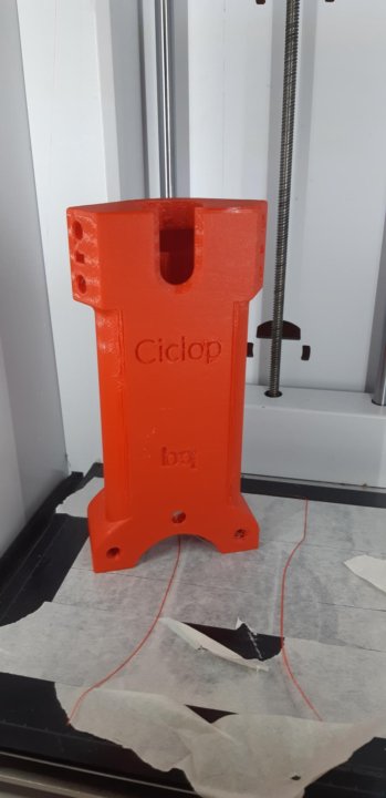
In general, I realized that I am not an adept of such creativity, and I have a suspicion that it is easier to model objects from scratch that are easier for a scanner.
And complex ones - the scanner cannot cope with complex ones in normal mode, two lasers are not enough for it - blind spots remain. To fix this problem, you need to scan in other positions and then again suffer with the combination of clouds. No thanks.
As a result - the thing will fit only for learning the basics of laser scanning, for something more - absolutely useless. No, of course, you can get something with outlines similar to the original model, but on this (and this, taking into account all the tambourines with cloud processing), that's it. No wonder the Spaniards abandoned this case.
The store made sure - in the description it is honestly stated that the result depends on the position of the planets and the mood of Aunt Sonya from the third floor.