Vertex 3d printer
Vertex Delta 3D Printer
Vertex Delta 3D PrinterHome / Vertex Delta
Product
A user-friendly and reliable 3D printer with never-before-seen innovations, designed to print refined objects to complete your projects.
Advanced safety features, a filament run out detector, a mid print filament replacement function and automatic calibration and bed compensation are only a few of the latest technological additions.
Open-source and designed in Belgium.
Now available!
Buy now
InstructionsDownloads
Videos
The Vertex in action
EXTRUDER
- direct drive extruder
- reliable feeding and extracting of 1.75 mm filament
- filament runout detector, the Delta will automatically pause and reload
- change filament function while printing, so you can print one object with multiple filaments/colours
BASE
- automatic first-time set-up calibration (no manual calibration needed)
- automatic bed compensation
- automatic SD card recognition
- 128 x 64 graphic display with blue backlight
PRINTHEAD
- actively cooled nozzle assembly with 3 high-quality fans
- effective pause function without nozzle leakage marks
- E3D compatible brass nozzle with 0.
35mm diameter
- advanced safety features, such as printhead angle and overheat protection with electronic accelerometer and temperature sensor
PRINT BED
- removable 4mm tempered glass build plate
- sheet of custom BuildTakTM as print surface (consumable)
- large build platform diameter of 200 mm and a 225 mm build height
MAGNETS
- backlash free magnetic diagonal rod coupling
- easy to assemble
- easy to switch printheads
ALUMINIUM FRAME
- rigid aluminium extrusion risers
- 4 mm aluminium top and bottom plates
- easy to assemble
HYBRID KIT
- quick and straightforward build (+-2 hours build time)
- base, printhead and extruder are pre-assembled.
- no soldering required
Specifications
Technical information
- print technology: Fused Filament Fabrication (FFF – FDM)
- layer resolution: standard 0.
 1 mm (maximum: 0.2 mm – minimum: 0.05 mm)
 - large build volume: 200 mm build platform diameter (0/- 5 mm), 225 mm build height (0/+75 mm)*
- print speed: 20-50 mm/s (can go up to 75 mm/s)
- travel speed: 180-200 mm/s
- build plate surface: removable layer of BuildTak™ (K8800-BT)
- filament diameter: 1.75 mm (accepts all filament spools with a mounting hole = 53 mm) open filament policy
- prints: PLA, ABS, TPU, PET and others
- nozzle: E3D compatible
- nozzle diameter: 0.35 mm (one nozzle supplied)
- maximum nozzle operating temperature: 295°C
- bed compensation: automatic bed compensation performed by the nozzle (no manual calibration needed)
- calibration: automatic first-time set-up calibration
- couplers: backlash free magnetic effector-couplers
- advanced safety features: auto shutdown when print head detaches or temperature is incorrect (due to external causes)
- filament run out detector: automatic pause and reload when printer runs out of filament
- change filament function while printing: this means that you can print objects with multiple filaments/colours
- effective pause function: pause your print job without nozzle leakage
- end stops: infrared based end stops
* Depends on object diameter.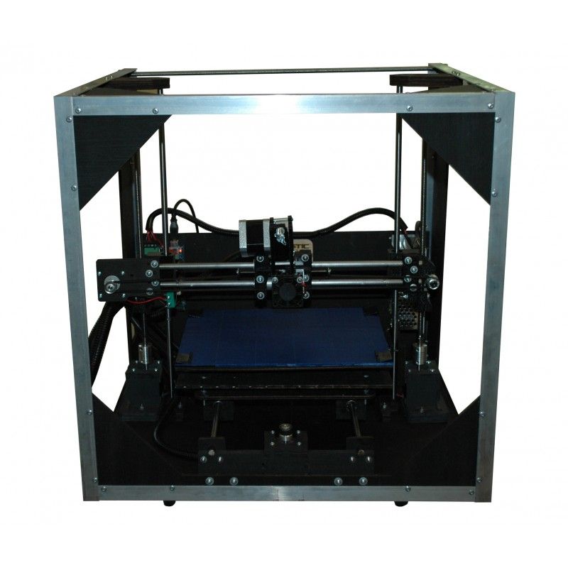 All specs and features are subject to modification.
- firmware: modified Open Source Marlin 3D Printer, firmware is user upgradable
- software: custom Repetier version (Windows) – Cura profiles (Mac)
- dimensions: W 35 x D 35 x H 77 cm (without filament spool)
- hybrid kit: quick and straightforward build, no soldering required
- frame: rigid aluminium extrusion risers and 4 mm aluminum top and bottom plates for a sturdy frame and precision ground 100 mm vertical rods and brass bushings
- fully Open-Source (hard- and software) and high quality parts
- weight: 10 kg
- ambient operating temperature: max. 30°C
- storage temperature: -10°C to +50°C
- communication: SD card or USB 2.0 (automatic SD card recognition)
- controller board: AVR ATmega2560 based
- AC input: 100 – 240 VAC 50-60 Hz 90 W max.
- display: 128 x 64 graphic display with blue backlight
We use cookies to ensure that we give you the best experience on our website.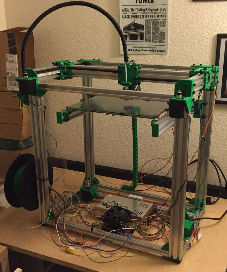 If you continue to use this site we will assume that ypu are happy with it. Read more
K8400: Velleman : Vertex 3D Printer Kit Open-Source for PLA and ABS 1.75mm Filament : Electronic Kits & Projects
Back to top
Overview
Vertex 3D Printer Kit
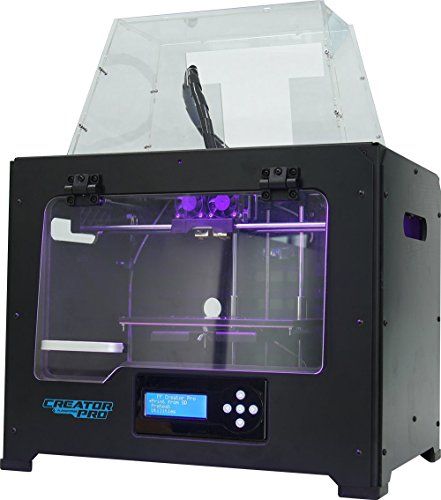
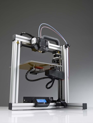
The Velleman Vertex K8400 Three Dimensional (3D) printer is the next generation Velleman 3D printer kit. Easy, accurate, affordable and open source. The K8400 is easy-to-assemble and offers features that rival those of printers that cost up to three times as more!
K8400 Standard Print Features
Create precise 3D prints with 1.75mm filament and 0.05mm layer resolution. Reaching up to temperatures as high as 270°C, the Vertex printer can print PLA (Polylactic acid) and ABS (Acrylonitrile Butadiene Styrene), as well as other plastics.
Stand Alone Printing
The K8400 3D Printer Kit comes standard with an LCD backlit screen from which you can command stand alone printing. Stand alone printing allows you to control every aspect of your printing job, print from an SD card, and refill filament using simple commands. The Vertex K8400 is compatible with all common and freely available open source 3D printer software packages.
Extruder
The extruder on the K8400 is stainless steel with a filament pulley wheel. Use the built-in setting for loading and unloading filament for your creations. The extruder is ultra-reliable with 1.75mm filament. See below for additional extruder option, which you can add on to the K8400 to make it capable of printing two colors simultaneously.
Printing Platform
The K8400 platform is made up of a 4mm aluminum frame (fixed), 4mm glass plate (removable), and Buildtak sheet. The platform frame is level and sturdy, while the Buildtak sheet on top makes the ideal print surface. View below for information on additional Buildtak print surfaces for your printer.
Bearings
K8400 bearings are easy-to-maintain plastic and remain silent while create with your Vertex. Bearings and Z axis are manufactured to provide ultimate stability in your 3D print space.
Specifications
Printing
- Print Technology: Fused Filament Fabrication (FFF)
- Layer Resolution Standard: 0.1 mm (Minimum: 0.05 mm - Maximum: 0.2 mm)
- Build Plate: 215 mm x 240 mm (8.46 in. x 9.45 in.)
- Build Volume: 180 mm x 200 mm x 190 mm (7 in. x 7.8 in. x 7.5 in.)
- Print Speed: 30 mm/s - 120 mm/s
- Travel Speed: 30 mm/s - 300 mm/s
- Build Plate Surface: Removable layer of BuildTak™ (consumable, also sold separately)
- Filament Diameter: 1.75 mm (accepts all filament spools with a mounting hole = 53 mm). Open filament policy.
- Prints: PLA, ABS Testing with other materials in progress.
- Nozzle 1 & 2 Diameter: 0.35 mm One nozzle supplied. Second nozzle optional.
- Distance Between Nozzles: 23.7 mm
- Maximum Nozzle Operating Temperature: 270 °C
Software
- Firmware: Modified Open Source Marlin 3D Printer Firmware - user upgradable
- Software: Repetier - CuraEngine - Slic3r (RepRap compatible)
Hardware
- Dimensions: X Y Z 360 mm x 380 mm x 395 mm (14 in.
 x 15 in. x 15.5 in.) (without filament spools)
 - Frame: Polycarbonate panels and fibre reinforced molded ABS parts
- Weight: 10 kg
- Average Noise Level During Operation: 52 dBA (at 1 m)
- Ambient Operation Temperature: Max 25 °C
- Storage Temperature: - 10 °C to + 40 °C
Electrical
- Communication: USB 2.0 or SD card
- Controller Board: AVR ATmega2560 based dual head and heated bed capable
- Display: 4 x 20 char. blue LCD with white backlight
- AC Input: 100 - 240 VAC 50-60Hz 150W max.
Report a problem
Suggest a product
Back to top
Specifications
No specifications are available at this time. Call for more information.Report a problem
Suggest a product
News
Subscribe to
Subscribe
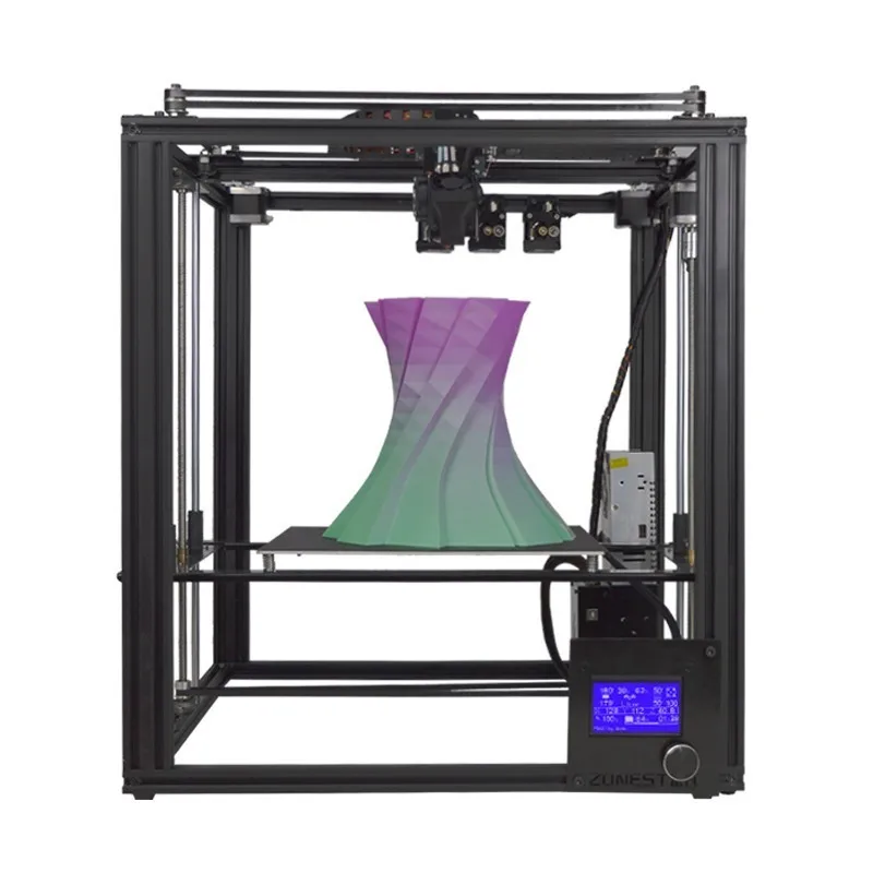
Z.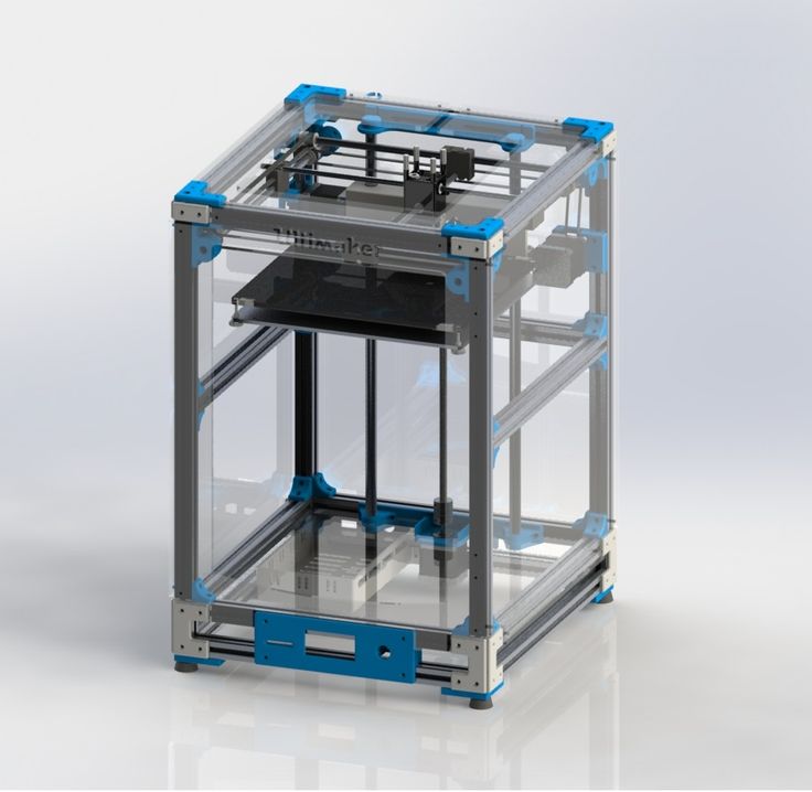 The desktop additive system can be used for both oversized 3D printing and small-scale additive manufacturing.
This 3D printer has already been featured in several reviews under the designation CR-30. In the additive community, the idea of conveyor 3D printers has been floating around for a long time, at least twelve years, but commercial versions have only recently begun to appear: Blackbelt in 2017, Powerbelt Zero in 2019, from the open source versions, the White Knight project can be mentioned. Another promising option called Printrbelt was never brought to market due to the untimely demise of Printrbot.
It was only a matter of time before an analogue appeared in the assortment of leading Chinese manufacturers of 3D printers, and already on November 18, everyone will be able to apply for Creality's system, called 3DPrintMill. The development of our own version of a conveyor 3D printer was promoted by Naomi Wu (a.k.a. SexyCyborg), a DIYer familiar to our community members, who has been collaborating with Creality for a long time.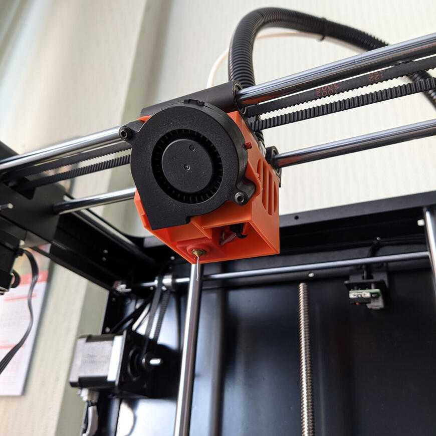 Perhaps the main factor was the cost: the price range among the above offers is wide, reaching up to €12,500, and Creality offers a very affordable option: early Kickstarter campaign participants can place orders for as low as $538.
As you can see in the illustrations, the distinguishing features of these 3D printers are the guides mounted at an angle of 45 ° to the surface along the X and Y axes, as well as the conveyor belt. You can get confused with the coordinate system, but imagine that a slightly skewed 3D printer is lying on its back - then the CoreXY kinematics are mounted on the portal with the appropriate coordinates, and the belt moves along the Z axis. The tilt of the portal, coupled with the translational movement of the belt, provides the ability to build parts in height without the need to rollback the entire model. In other words, this scheme allows you to print parts of theoretically unlimited length - just remember to attach the roller table and open the window.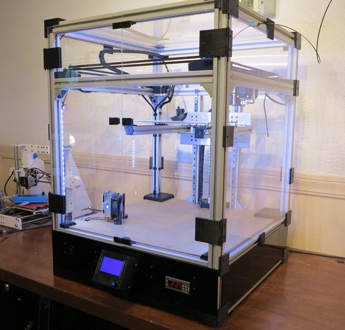
Alternatively, this 3D printer can be used for in-line production, printing one part after another and allowing the models to separate themselves from the tape at the end and fall into a container. From an economic point of view, serial 3D printing will be justified as long as we are talking about relatively small batches of products, measured in hundreds or thousands of pieces.
Polylactide, PET-G, and TPU are listed as consumables, but there is a heated platform in the work area under the belt. The wear-resistant conveyor belt is made on a nylon base, apparently with the addition of carbon fibers. The system is calibrated at the factory, equipped with quiet drivers, a massive airflow with three fans is installed on the head. Additional features include a filament sensor, save and resume function, plus a card capture reader for offline operation. Frame made of aluminum profiles with V-shaped rollers and guides reinforced with corners. Given the unusual coordinate system, the preparation of machine code requires special software - for this purpose, the company offers a specialized slicer CrealityBelt.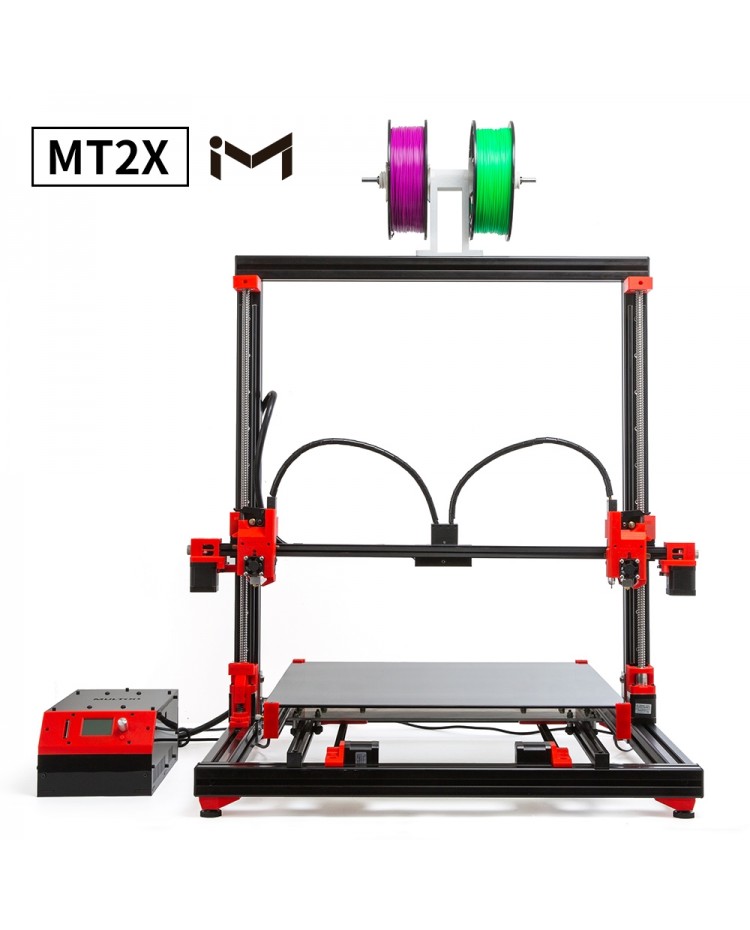
Specifications of 3DPrintMill 3D Printer (CR-30):
- Print technology: FDM
- Number of extruders: 1
- Construction area size: 200x170x∞ mm
- Printing accuracy: ±0.1 mm
- Nozzle diameter: 0.4 mm
- Layer thickness: 0.1-0.4 mm
- Hot end temperature: ≤240°C
- Heating temperature: ≤100°C
- Power consumption: 350W
- Power supply: AC 100-120V / 200-240V, DC 24V
- Consumables: PLA, PET-G, TPU
- Filament diameter: 1.75 mm
- Interface language: English
- Data transfer: USB, SD card
- Software: CrealityBelt Slicer
- Dimensions: 535x656x410 mm
- Weight: 16.5 kg (net), 20.5 kg (gross)
The start of accepting orders is scheduled for November 18, 19:00 Moscow time.
You can subscribe to the notification about the start of the campaign here.
FFF fdm CREALITY 3DPrintMill CR-30 conveyor
Follow author
Follow
Don't want
11
More interesting articles
ten
Follow the author
Follow
Don't want
German startup iFactory has announced the third model of a conveyor FDM 3D printer with unlimited...
Read more
5
Follow the author
Subscribe
Don't want
Rostec State Corporation presented at Weldex-2022 a vacuum cathode-beam. ..
..
Read more
Loading
04/01/2016
39696
68
Subscribe to the author
Subscribe
Don't want
News from the world of printing in a short line
FDplast announced the release of a free...
Read more
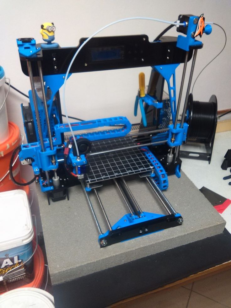
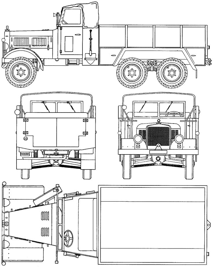
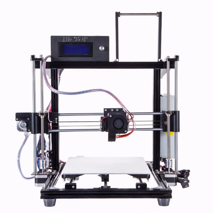
How to make a 3D printer: drawings, parts, instructions for making and assembling
- October 19, 2018
- Production
- Ivan Frolov
Today, new technologies appear almost every day. Over the past decade, people have seen countless innovations that have really changed the world around them. Perhaps one of the most monumental was the invention of the 3D printer, a device that can create real, tangible 3D objects from digital design details. There are many types of 3D printers, each using different print materials, including plastics, metals, ceramics, food (chocolate) and more.
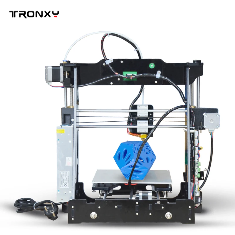
Many users would like to have this novelty at home. This is exactly what manufacturers are counting on, releasing kits for creating a printer from scratch for advanced users of various levels. Before making a 3D printer, they carefully study their capabilities and select the right model on the Internet.
History of 3D printing
3D printing has had a long history, during which it has had various names such as stereolithography, 3D stacking, 3D printing. The last name stuck and became the most common. At the end of 19In the 1980s and early 1990s, there was an increase in the production of additives used for rapid prototyping, known as RP. Printing on the basis of this consumable takes time from several hours to several days, depending on the selected project. RP models are created using computer-aided design known as CAD.
Before making a 3D printer, soft-machines are selected that can independently determine the way to create a layout.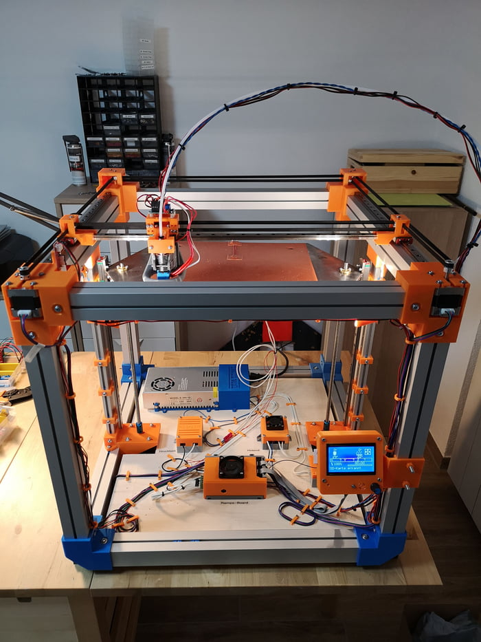 Thus, the procedure for building products that are printed in layers became known as three-dimensional printing. The first 3D printing took place at the Massachusetts Institute of Technology. Early 19In the 90s, MIT initiated a practice that was certified as 3DP, after which, in fact, the history of 3D printing began. In February 2011, the Massachusetts Institute of Technology licensed 6 corporations and offered 3DP for their products.
Materials for 3D printing
The process of selecting printing materials for 3D printing began already from the moment the printer was created. Today, the industry offers a fairly large selection of consumables. Before you make a 3D printer, you need to be able to choose the right type of materials for printing:
- Acrylonitrile butadiene styrene (ABS) is a popular material for early 3D models. It is very strong, slightly flexible and can be extruded easily making it ideal for this type of printing. The disadvantage of ABS is that it requires a higher temperature than, for example, PLA material.
 To print ABS materials, a temperature of 210-250 0 C is commonly used.
 - Polymagnetic acid (PLA) is another common material among 3D printing enthusiasts. It is a biodegradable thermoplastic that is obtained from renewable resources. As a result, PLA materials are more environmentally friendly than other plastics. Another feature of PLA is its biocompatibility with the human body, which must be considered before making a 3D printer for home use. The structure of PLA is more complex than that of ABS, and the material melts at 180-220 0 C, which is significantly lower than that of ABS.
- PVA (polyvinyl alcohol) fibers are easy to print and are used to support the object during the printing process for models with projections that cannot normally be printed. This type of filament is an excellent material for a dual extruder 3D printer. It is based on polyvinyl alcohol, so it has good properties, the main ones being non-toxicity and biodegradability after dissolving in water.
 It is this material that creates the prospect of a business on a 3D printer.
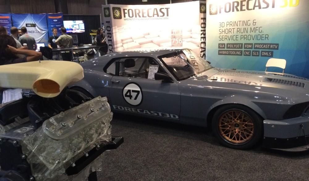
The user does not have to 3D print with plastic. It is theoretically possible to print objects using any molten material that solidifies quickly enough. In July 2011, researchers at the University of Exeter in England unveiled a prototype food printer that can print 3D objects using melted chocolate.
Print file format
Printing with a regular printer is possible if it understands the document format. This ability is similar for 3D models, therefore, when making a 3D printer with your own hands, you first choose the format for printing future models. STL file is one of the most popular file formats for 3D printers. It is supported by a wide variety of devices, and many files can be found in 3D model repositories based on this format.
STL stands for STereoLithography or Standard Tessellation Language. It was originally one of the main formats in CAD software created by 3D systems. This format can now be found in many 3D printing software packages and is simple and easy to output, which is one of the reasons why it has become popular.
OBJ (Object Files) is another popular printer file format for DIY 3D printer users. It was originally used in the Advanced Visualizer animation package developed by Wavefront Technologies. An OBJ file is a 3D geometry and contains several different attributes:
- vertex normals;
- geometric vertices;
- polygonal edges;
- texture coordinates.
Print object files can be in either ASCII (.obj) or binary (.mod) format.
3D Printer Design
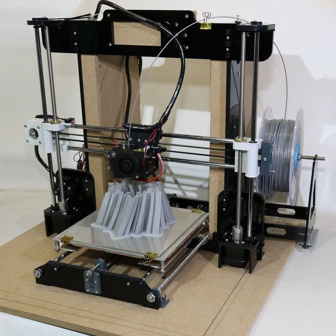
The first step in the printer design process, before assembling a 3D printer, is to look for the simplest design, such as Maker Mendel or RepRap mockups, which use the shape of a box as a template for the body. Some inventors use ordinary wooden or plastic boxes to base the printer, the elements of which can be interchanged to fit the layouts of future 3D printed parts. This design will become the future basis for the printer.
A belt configuration is then selected that will provide an effective basic design. For the ability to interact with the Arduino, choose a controller. The 3D models were developed using SolidWorks. The structure is assembled according to the drawings, having previously manufactured metal and wooden parts for a 3D printer, as indicated, for example, in the drawings below.
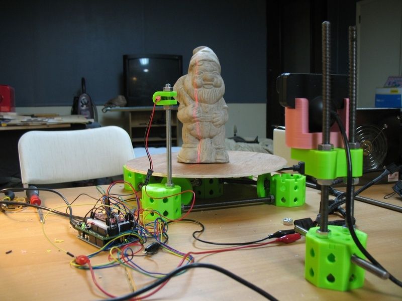
A 3D object needs three axes to be represented in 3D print space. The goal is for any point in space to be represented by three coordinates, which are usually listed in the order X, Y, Z. Each coordinate provides information about one direction or axis, each of which is perpendicular to the other two. One coordinate indicates the position along the line, two in the plane, and three in space.
3D printing uses various mechanisms to maneuver on a certain axis, which is clearly indicated on the drawings of the 3D printer. They have two common systems: Cartesian and Delta, use FDM technology, have different mechanisms for navigating the extruder within the print space. Fused deposition modeling uses a thermal deposition polymer to create layers. This process is very dependent on the X, Y, and Z axes of the 3D printers.
Depending on the printer in question, the hot end will move in one, two, or all three of these axes. So the axis system makes the 3D printer work and gives the depth and design of the object. If there were only two axes, let's say the X and Y axes, then the design of the object would be flat, which would be similar to printing with an inkjet printer. Typically, the X and Y axes correspond to lateral movement, and the Z axis corresponds to vertical movement. To avoid confusion when assembling a 3D printer, the following position of the axes is taken as a basis:
- Z is detected when the user is facing in front of the 3D printer, then the tool moving up and down is the Z axis.
- X is the tool moving left or right, and the tool moving back and forth is the Y axis
Making the device frame
Linear rods are cut to size according to the drawings. For example, the middle rods are 260mm and the side rods are 250mm long. Slide the side linear rods into blocks, they will be the Y axis. Place a linear bearing on top of each block and mark where the holes should go. Drill these holes with a drill for screws in order to further hold the bearings. Mark holes in the thinnest part of the block and drill two holes with a diameter of 8 mm.
Place the middle linear rods in these holes - this will be the X axis. Rotate the block so that the linear bearing is at the bottom. Lay two timing pulleys centered between the mounting holes for the linear bearing. Place a screw through the toothed pulleys, using a screwdriver to fix them to the housing. These blocks allow the extruder for a 3D printer to move along the Y axis. This is the simplest layout of a printer body. It is possible to make an extruded aluminum frame with 8 holes in the gussets, which works well and provides a rigid and stable structure.
This project has been redesigned to use a linear rail and a matching bearing.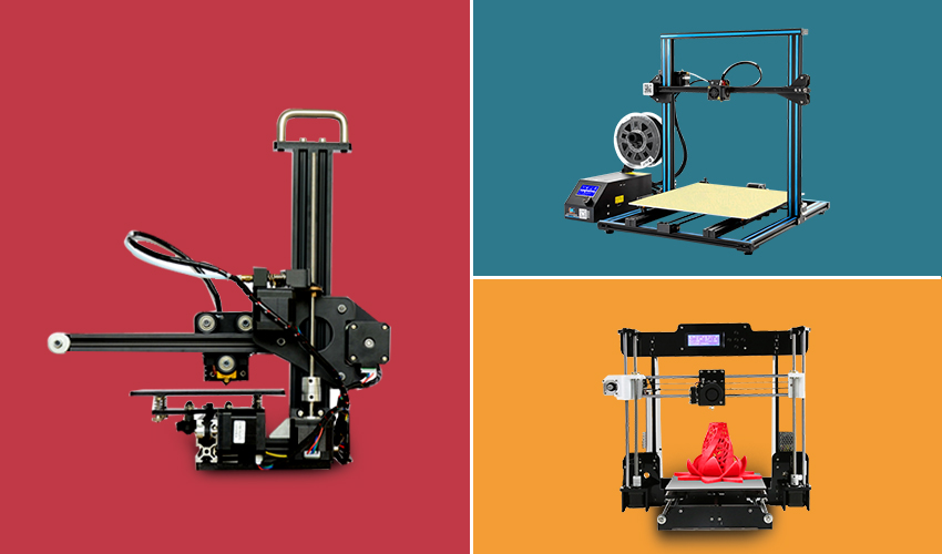 The sled has holes for mounting standard limit switches for the X and Y axis. Mark the block on both sides in the center, 2 cm from the longest edge. Make a hole with a drill. Secure with nuts all the screws in the mounting holes. Fasteners must be rigid. Place the shaft connectors on the two remaining stepper motors and use a hex wrench to tighten them properly.
Place the screws on the other end of the coupling and tighten them again. Use zip ties to secure stepper motors to the bottom of the case. Place the mounting plate support on the threaded screws and loosen the screws to lower the plate. Slide the top plates over the threaded connections to make sure everything is in place.
Creating the X axis
The X axis is the most complex axis, when building a homemade 3D printer, it is in direct connection with the Z axis, and also supports the extruder. First, attach an 8mm bolt to the X-axis using nuts of the appropriate size. Then carefully advance the two bearings inside the gaps and do the same with the X axis motor. Then insert the bearing into the X axis axle pulley and attach it with a screw and nut. Two nuts on the bearing serve for stability and protection against self-unwinding.
Parts for the X-axis tensioner are now assembled. This part will be inserted into the X-axis slot. One bolt will be used to tension the belt and the other to attach the steel bars to the X-axis. Use an 8mm drill to align the 4 holes for inserting the X-axis rods.
Before continuing with assembly, assemble the other part needed to attach the hot end of the extruder. Add linear bearings to the printed part and secure them with cable ties in the belt that controls the X axis. In order to continue creating the X axis of the 3D printer device, first complete the mounting of the Z axis.
Use 8mm x 320mm thick smooth steel rods and slide the X axis wheel and running gear linear bearings inside each of them. To do this, it may be necessary to loosen parts of the Z-AXIS-TOP. The Z axis is finished and the smooth steel rods for the X axis can be moved, remembering to attach the X-CARRAGE and run the horizontal X axis rods through it.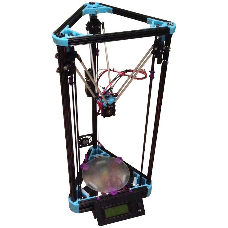
The X axis running gear will run on the left side and the right side will have the X axle idler along with the pulley and tensioner parts. At this point, you can attach an X-axis stepper motor with a GT2 gear, and add a belt. Now use the bolts to hold the X-axis bars in place and the M4 bolt tighten the belt.
Mounting the Y-MOTOR Axis
Once the base of the frame is built, you can continue to complete the mounting of the Y-axis. To do this, you will need the following 3D printer parts:
- NEMA 17 HR 0.9 degrees per step 4.0 kg/cm stepper motor.
- Part number: 42BYGHM809.
- 20 tooth pulley GT21 meter timing gear GT2.
- Screws 5x M3 x 12 mm.
- Washers - 4x M3.
- Nuts - 2x M3.
Start by attaching the stepper motor to the Y-MOTOR part on the back of the frame. Also attach the GT2 pulley to the motor shaft. Then you need to adjust it.
Next, connect the Y-BELT-HOLDER to the platform platform.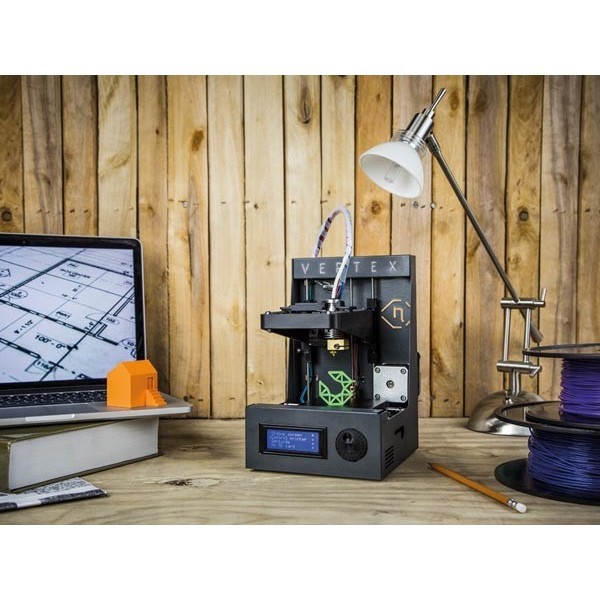 Use M3 x 12mm screws with washers and nuts. The Y axis will be moved using the GT2 belt. Now attach the GT2 belt and wrap it around the GT2 pulley. Fasten the strap to the Y-BELT-HOLDER with cable ties, and adjust the strap tension with the M4 screw on the Y-stand.
Installation of the extruder
After the table for the 3D printer is ready, the extruder is installed. Place two linear bearings on the middle linear rods. Check how far apart the axial bearings are. Mark where they landed and where the holes should be. These holes are made with a drill. Fasten the linear bearings with screws. Next, you need to mark the middle of the block from the linear bearings and make other mounting holes. Place the guide rods against the middle of the four holes. Move the extruder to secure the extruder in place. This design will allow you to remove or upgrade it in the future.
The extruder consists of a thermistor that measures the temperature, a heating element and a die. The thermistor and heating element fit into the holes on the extruder head as shown in the figure.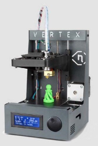 After the completion of the installation work, the electrical circuit of the extruder is connected.
Software setup
When the mechanical and electrical parts of the device are assembled, proceed to install the software and start preparing the RAMPS 1.4 board. Some board models are pre-assembled by the manufacturer, while others require users to solder multiple connectors. The RAMPS board must have jumpered connectors. Stepper motors move in steps, which allows them to be very precise.
Carefully connect the RAMPS boards to the Arduino. Make sure the Arduino USB is under pin D10. To get started download the latest official Arduino Environment software. When downloading, simply double-click on the link to start the installation, then agree to all the default options, including installing the USB driver.
Connect the Mega 2560 to the computer and test it. Insert USB cable into Mega and computer. In this case, a separate adapter is not needed, the power supply for the 3D printer will be used. The computer itself will install the necessary drivers from the software installed earlier. The user can see which COM port is set.
If the software uses a localized language, you can change it by following the steps: File -> Settings -> Editor Language -> Language Selection. Reload the Arduino software. Perform the initial setup of the Mega. Select the model: Tools -> Tip -> Arduino Mega or Mega 2560. The PC remembers this choice for future use.
The port number on the system may vary. If it is not clear which one to choose, check the listed COM numbers and then disable Mega. Define a new view in "Tools -> Ports" to set which ones are used by other elements and which ones are missing. To do this, download the program, press the arrow pointing to the right to download Mega. The code is compiled, loaded and activated. One of the LEDs on the Mega is now blinking, the device is ready to go.
Next, configure the Marlin firmware. Open the Arduino IDE: File -> Open, then go to the Marlin-Development folder and the Marlin folder. Select and open the Configuration.h or Marlin.ino file. A new window opens containing Marlin.ino and open the Configratuin.h tab.
Specify the motherboard as RAMPS 1.4 with accessories. Open the required variables which are in Configuration.h -> Press CTRL + F to open the search box and write RAMPS. Click "Find" to set the line containing: #define MOTHERBOARD.
Find the RAMPS board - these are the devices connected to D8 (Heat-bed), D9 (fan) and D10 (heater) which are usually defined in the schematic. E - for extruder, F - for fan, B - for bed. Make sure the line reads: #define MOTHERBOARD BOARD_RAMPS_13_EFB.
Save the file if any changes have been made. Set the speed. The default base speed is 250000. If this creates any problems with the computer, then you can change it to 125000.
Open Configuration.h. Find a line containing #define BAUDRATE 250000 and precede it with two slashes, for example: // #define BAUDRATE 250000.
Write on a new line: #define BAUDRATE 125000. Save the file. Extruders are defined as 1 by default, so leave this value unchanged.
Start determining the temperature settings. There is a list with 20-25 different options for each sensor. Listed below are the parameters that define the sensor inputs on the RAMPS 1.4 board. The default is SENSOR_0 with option 1 which means that // 1 is a 100x thermistor - the best choice for an EPCOS 100k (4.7k Pullup), or in other words it is a standard thermistor used to measure temperature for 3D printers.
You can define MINTEMP as 0 by writing:
- #define HEATER_0_MINTEMP 5//.
- # define HEATER_1_MINTEMP 5//.
- # define HEATER_2_MINTEMP 5//.
- # Define Heater_3_MinTEMP 5.
- #DEFINE BED_MINTEMP 5.
Maximum default temperature:
- HOT-END: 150. 9000 9000 9000 9000 9000 0 C or so. Delete // on line with BED_MAXTEMP. If the user needs more complex settings, then they refer to the instructions for setting up the software on the profile site.