3D printing step files
STL vs. OBJ vs. IGES vs. STEP: An Overview of 3D File Types
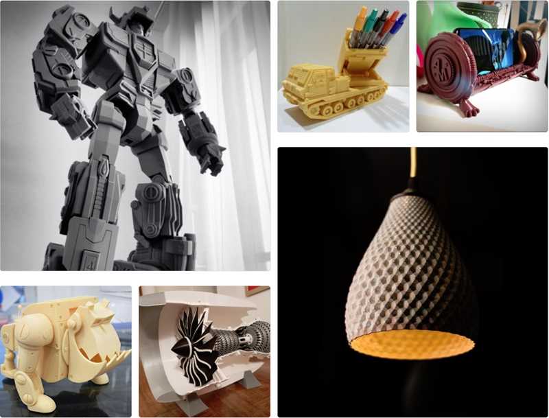
Are you a creator working on a product launch? Or a designer submitting updated files while prototyping? Regardless of your CAD preference and use case, whether it be SolidWorks, Creo, Catia, or Siemens NX, your files will need to be exported sooner or later. But the question is, in what format? This article will dive into the most common 3D printing file types used for exporting 3D models, when you should use each of them, and why. These file types include STL, OBJ, IGES, and STEP.
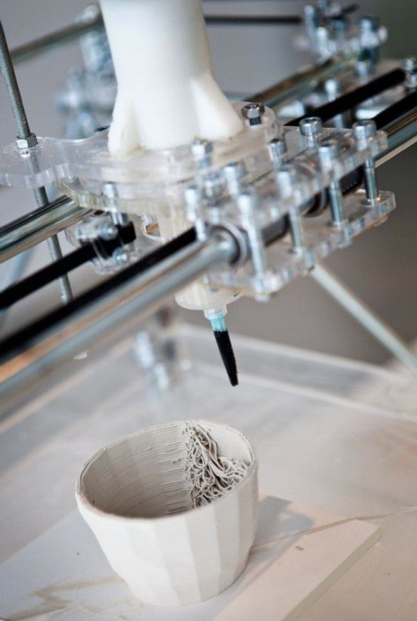
STL (StereoLithography)The STL filetype has been around since 1987 but has exploded in popularity in recent years, as 3D printers have become more commonly used. It is the go-to filetype when it comes to 3D printing. An STL file will store objects as sets of vertices joined by edges to make triangular faces, which is where the misconception of STL standing for Standard Triangle Language or Standard Tessellation Language comes from. These triangles result in the inaccurate representation of previously curved surfaces as tessellated surfaces. Generally speaking, these tessellations do not cause a problem for 3D printing, as long as the mesh and the intended model have discrepancies smaller than the resolution of the 3D printer.
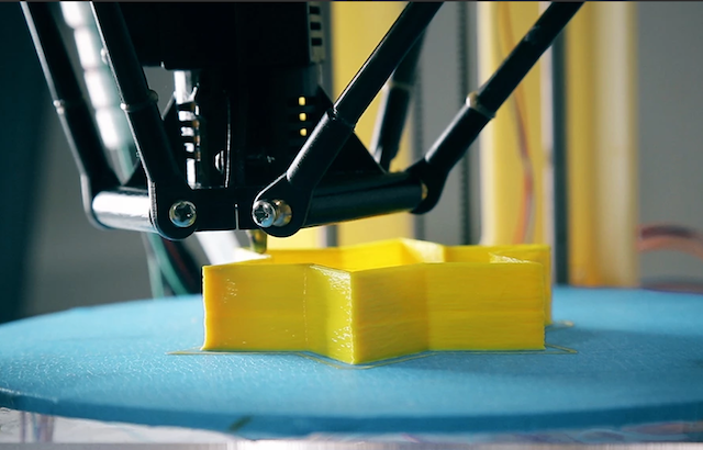
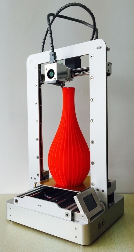
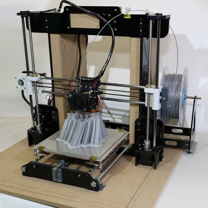
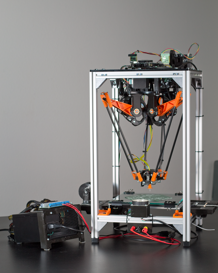
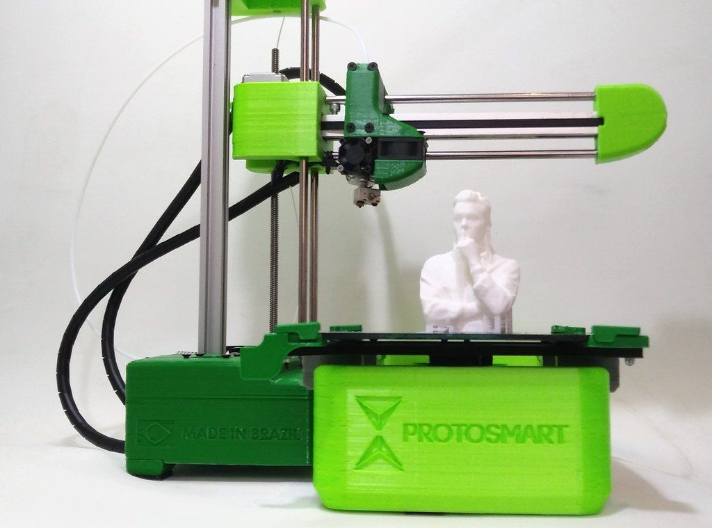
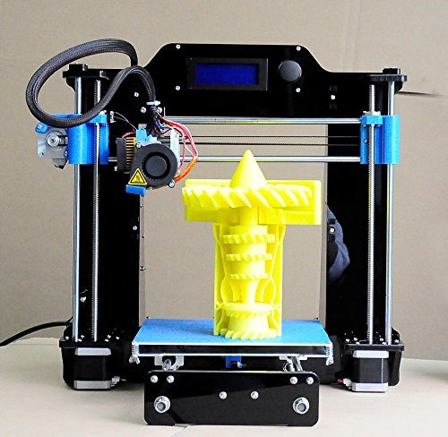
3D Printer Printing STL File
OBJThe OBJ file format was developed by Wavefront Technologies, specifically for animations, but has since been adopted by the 3D community. Similar to an STL file, OBJ files are stored as a list of vertices joined by edges. However, unlike STLs, they support polygonal faces. Polygons allow for a closer representation of the original geometry than STLs do but still do not accurately portray the original geometry. With that being said, OBJ files can represent an object more accurately while using the same number of faces as an STL file.
IGES (Initial Graphics Exchange Specification)The standards for IGES were first published in 1980 by the National Bureau of Standards.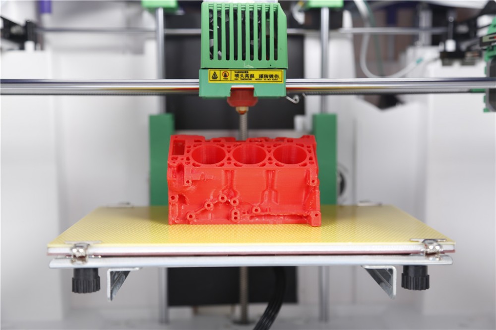 IGES differs from both STL and OBJ because it allows for the encoding of curves/curved surfaces instead of approximations using smaller, flat surfaces. The ability to encode curved surfaces allows IGES to maintain high accuracy while exporting the model. Although the export geometry is highly accurate, it is not perfect. Features such as splines will be converted to polylines during this process. IGES files also have the ability to store units within the file header.
In 1994, the International Standards organization developed the STEP file format to facilitate the move to Model-Based Definition. Like IGES, STEP allows for the more accurate storage of models by encoding curves and curved surfaces; however, it still suffers from small losses while encoding splines.
Unlike the other file types here, STEP files allow for incorporating engineering data such as materials or plastic-type used, geometric dimensions & tolerancing, and model intent within the model itself.
The ability to store additional data is attractive because it can eliminate the need to accompany 2D drawings and allow for annotations to be embedded within the model. STEP files are becoming more and more popular and are likely to dissolve the need for IGES.
ConclusionThe overall difference between these files comes down to the accuracy and detail at which they can store 3D objects.
All in all, the differences in how each file type records the geometries and details of an object can mean that each file type is better suited to a particular application. The approximation provided by STL and OBJ files is suitable for use in 3D printing and graphics. In contrast, the higher precision and more accurate features supported by IGES and STEP files are much better suited to CNC milling and CNC lathe applications like making a mold.
| Filetype | Overview | Level of Detail | Application |
| STL | STL files store objects as sets of vertices joined by edges to make triangular faces. | Medium-Low | 3D Printing |
| OBJ | OBJ files store 3D information as a list of vertices joined by edges, and unlike STLs, they support polygonal faces that allow for a closer representation of the original geometry. | Medium | 3D Printing (it includes object color and texture information) |
| IGES | IGES is similar to OBJ, however, it is able to encode curves and curved surfaces rather than an approximation using smaller, flat surfaces. | Medium-High | CNC |
| STEP | STEP is similar to IGES, but it includes engineering data such as materials, geometric dimensions & tolerancing, and model intent within the model itself. | High | CNC & Injection Molding |
Lastly, it is important to consider that once an object is exported to a file type containing less accurate information about the model, it can become challenging to recreate the original geometry from that object. The file type you use may even affect product design in early stages.
EngineeringJaycon Systems3D Printing, CAD, Mechanical Engineering, 3D File Types, Software Development, Engineering
0 LikesSTEP File: Definition - How to View and Make a STEP File
STEP files and the STEP format was developed so that users can access, edit, and share 3D models across many CAD programs. STEP (Standard Exchange for Product Data, also called ISO 10303 or .STP) format was designed for compatibility by the ISO technical committee on automation systems and integration. The file format saves the whole shape of 3D objects beyond mere topography. Effectively all CAD programs can decode information from STEP files which means they can act as the common through-line across multiple CAD apps. This article will discuss the STEP file definition, the format’s history, and some of the programs that use it.
What is a STEP File?
STEP is a common file format used to read and save 3D models in a way that nearly all CAD systems can interpret. The format follows standards suggested by the ISO technical committee on automation systems and integration. Its main purpose is to enable cross-compatibility.
What is in a STEP File?
The STEP file configuration contains:
- The data of 3D model images in text form.
- The proper formatting to access, store, and export data to multiple CAD apps.
- Important data such as: the date of creation, the name, and the origin.
Who Created the STEP File Format?
The STEP file format was created by the International Organization for Standardization (abbreviated as ISO). This technical committee develops and regulates technological standards. They began developing the STEP file format in the mid-1980s, configuring it to be accessible by various CAD programs. The first version wasn’t available until 1994, and other versions have been released in the succeeding years.
How to Convert a STEP File?
The steps to converting any other CAD file into STEP format depend on the software or tool used. Follow that program’s methods when exporting files. The general steps usually look something like:
- Open the software (for example FreeCAD).
- Click on ‘File’.
- Choose ‘Export’.
- Save as STL.
One of the benefits of the STEP file format is that it's compatible with many CAD programs. For example, if the file was made in Autodesk, it can still be read in SolidWorks and no data will be lost in between. To 3D-print the item, however, it has to be converted to STL. For more information, see our guide on how to convert a STEP File to an STL file.
How to View a STEP File
A STEP file can be opened in nearly any CAD program including simple viewers such as FreeCAD, VariCAD, and BRL-CAD which are available for free. To open it:
1. Locate the STEP File on Your PC or Device.
Locate the STEP file in its folder or by typing “Step” in the taskbar search field.
2. Select File > Open With a Double-Click or a Right-Click.
Select the STEP file by either double clicking on its icon or right-clicking, mousing over “open with,” and clicking the CAD program you wish to use.
3. Open Using the STEP Reading Software That has Already Been Installed.
Alternatively, you can open your preferred CAD viewing software such as FreeCAD, VariCAD, or BRL-CAD. Within the program, click “File,” then “Open,” and select the proper STEP file.
How Can I Make a STEP File?
Most CAD apps, including big names like Autodesk, SolidWorks, CATIA, SolidEdge, and Creo, can save files in STEP format. There is also an option to save multiple components in a single STEP file. To save in STEP format:
1. Make a New File With your Preferred CAD Program or Software.
Choose your CAD program and open a new project. Most file formats are acceptable at this stage.
2. Make Changes to Your File.
Build your part in the digital environment. Make any adjustments you need.
3. Use the File Extension .STEP or .STP Based on Your Options.
If you have not yet saved the file, select “Save,” and choose .STEP or .STP as the file type. If you have already saved it in a different CAD format, most programs will have an option to “Save As” or “Save a Copy” that will let you save in the .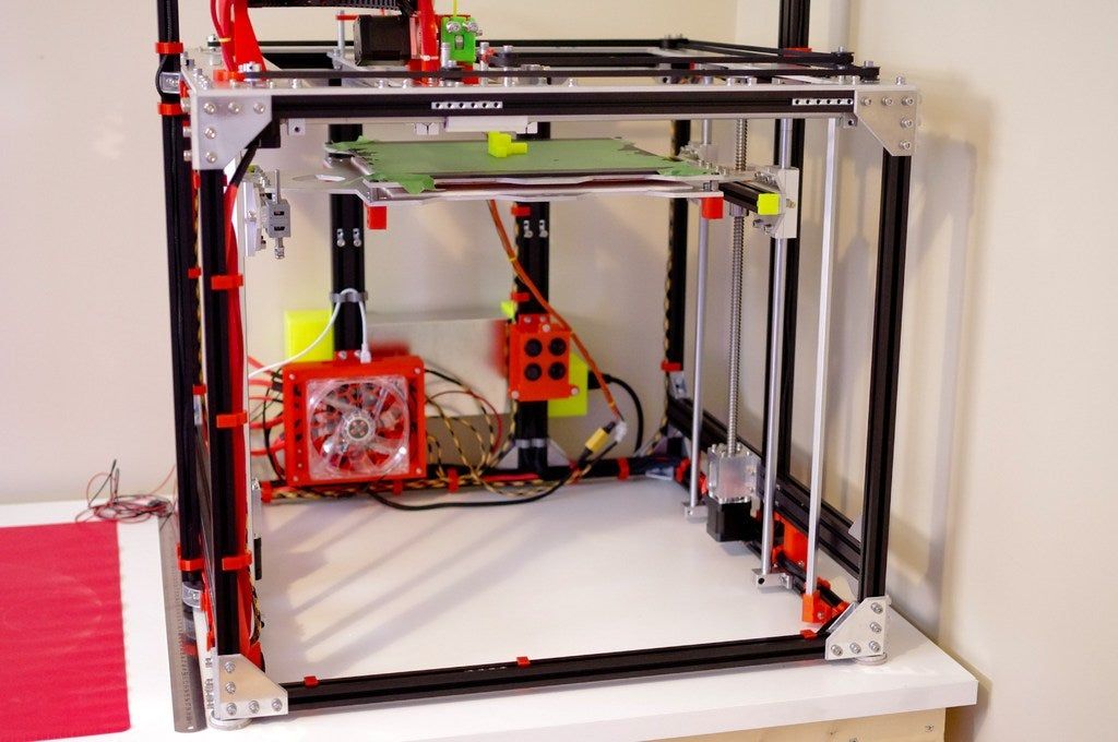 STEP or .STP format. If that’s not an option, you should still be able to export it as a STEP file.
What is the Importance of a STEP File?
STEP files are valuable to engineers because they make CAD data much easier to share. Nearly all CAD programs can open and manipulate STEP files. Therefore, the design process’ various stakeholders (architects, civil engineers, industrial engineers, manufacturers, etc.) can each view and edit the design using whichever program best suits their needs. The person prepping the part for CNC milling, for instance, does not need to buy and learn the designer’s specific software.
What Are the Types of Step Files?
Though STEP files all get saved with a .STEP or .STP extension, there are several different subtypes:
- AP203 (Application Protocol 203): Describes the 3D-model’s topography, geometry, and configuration management data.
- AP214: Contains the same information as the AP203 type, but adds model color, dimensions, tolerances, and design intent.
- AP242: Incorporates AP203 and AP214 mechanisms plus features like digital rights management and archiving.
What Are the Best STEP File Converters?
The best STEP file converters are:
- FreeCAD: FreeCAD lets you view, edit, and convert CAD files to STEP format. It handles large files well.
- gCAD3D: gCAD3D can open and modify many file formats such as: STL, 3DS, FBX, and ASM. It can then convert them to STEP formatting as necessary.
- Gmsh: Gmsh is a converter software for Windows that generate 3D meshes. It can easily convert an STP file to other formats by simply using its Export option.
What Are the Best Applications for STEP files?
Realistically, the best application for STEP files is the CAD program you regularly use. Below are a few that come highly recommended:
- 3D Viewer Online: 3D Viewer Online is a web service that, as the name suggests, allows you to view 3D models (including STEP files) in your browser.
 Its paid versions also offer a wide range of upload and rendering settings as well as advanced embedding.
 - Fusion 360: Autodesk’s Fusion 360 is a fully-featured parametric CAD tool that is popular with students and professionals alike. It is an excellent tool for incorporating STEP files into a larger workflow, from design conceptualization to fabrication.
- Clara.io: Clara.io is a browser-based 3D modeling and file-sharing app that is popular for its photorealistic rendering capabilities via VRay.
Is a STEP File the Same as a CAD File?
A STEP file is a type of CAD file, but not all CAD files are STEP files. STEP is the standard designed by ISO and is cross-compatible with many CAD programs.
Summary
This article presented the STEP file, explained what it is, and discussed how to create, view, and convert the file type. To learn more about STEP files, contact a Xometry representative.
Xometry provides a wide range of manufacturing capabilities, including 3D printing and other value-added services for all of your prototyping and production needs.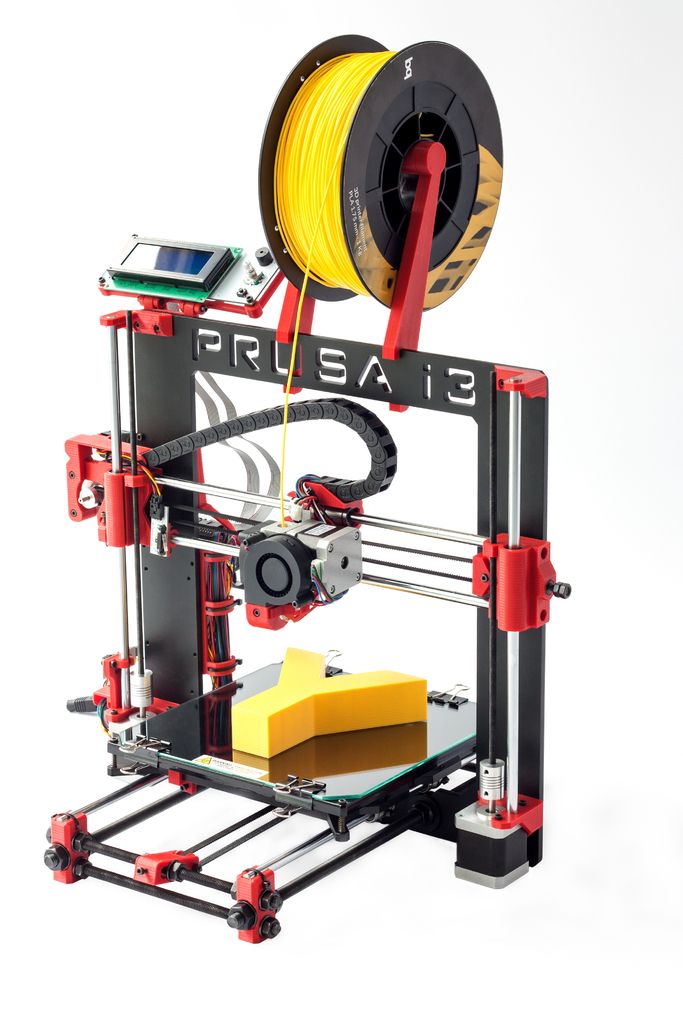 Visit our website to learn more or to request a free, no-obligation quote.
Disclaimer
The content appearing on this webpage is for informational purposes only. Xometry makes no representation or warranty of any kind, be it expressed or implied, as to the accuracy, completeness, or validity of the information. Any performance parameters, geometric tolerances, specific design features, quality and types of materials, or processes should not be inferred to represent what will be delivered by third-party suppliers or manufacturers through Xometry’s network. Buyers seeking quotes for parts are responsible for defining the specific requirements for those parts. Please refer to our terms and conditions for more information.
Team Xometry
This article was written by various Xometry contributors. Xometry is a leading resource on manufacturing with CNC machining, sheet metal fabrication, 3D printing, injection molding, urethane casting, and more.
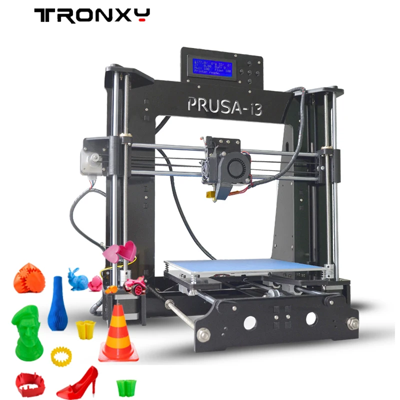
3D Printing STL Files: A Step-by-Step Guide - 3DPrinter
3D Printing STL Files: A Step-by-Step Guide
STL (stereolithography) additive technologies. Information about an object is stored as a list of triangular faces that describe its surface, and their normals. The STL file can be text (ASCII) or binary. It got its name from the abbreviation of the term “Stereolithography”, since it was originally used in this particular 3D printing technology.
All modern CAD (Computer Aided Design) programs allow you to export your own file format to STL. The 3D model is then converted into machine language (G-code) through a process called "slicing" and the model is then ready to be printed.
In this article, you will learn the basic steps required to properly export your models for 3D Printing.
Step 1: Resolution STL
The STL file format uses a series of linked triangles to recreate the surface geometry of a solid model. Increasing the resolution will use more triangles, better approximating the surfaces of the 3D model, but also increasing the size of the STL file.
If you export the file at too low a resolution, the model will have visible triangles on its surface when printed. In most cases this is not desirable, but they can be used to create "low poly" models with a digital look.
Increasing the resolution above a certain point is also not recommended, as it does not bring any additional benefit: very small details cannot be 3D printed, so the file size will be increased unnecessarily, making subsequent processing difficult.
Step 2: Export Options
You can change the resolution of STL files by changing the format options in the software. If you're unsure, choosing a preset is the safest option to create an STL file that fits 3D print .
Each CAD package has different STL resolution options, but most use two main parameters: chord height and angle.
Chord height is the maximum distance between the surface of the original 3D model and the surface of the STL file that the software can use. Using a lower chord height will help show the curvature of the surface more accurately.
The recommended value for the chord height is 1/20 of the thickness of the 3D printed layer and not less than 0.001 mm (1 micron). This will always produce an STL file with perfect accuracy for most 3D printing applications. Exporting at a lower tolerance will not affect print quality as most regular 3D printers are not capable of reproducing such a high level of detail.
Angular tolerance limits the angle between the normals of neighboring triangles. The default value is often 15 degrees. Some programs also specify this tolerance as a value between 0 and 1. If a smoother surface does not require a higher setting, the default value of 15 degrees (or 0) is recommended.
Step 3: Export STL files from your CAD software
Let's see how you can quickly and easily convert your file to STL format in different programs.
AutoCAD:
Important: STL export is only possible for whole 3D objects
- Enter “FACETRES” on the command line
- Set parameter FACETRES to 10.
- Enter command “STLOUT”
- Specify objects to export
- Press Y or Enter at the Create a binary STL file? [Yes/No]
- Specify a file name
- Save the file.
Autodesk 3ds Max (3D Studio Max)
- Open the File > Export tab)
- Select file type - StereoLitho *.stl
- Enter file name
- Save file
- Select type Binary
- Press OK
Autodesk Inventor / Mechanical Desktop
Important: you can export both individual parts and whole parts of the model
- Open Manage tab > Update panel > Rebuild All
- Then open File > Save as > Save Copy As
- Select STL file format
- Enter file name
- Set the following parameters: Format - binary (Format > Binary), units - mm or inches (Units > mm, inches), resolution - high (Resolution > High)
- Save file
Google Sketchup
If you are using Sketchup Standard and not Pro, you will need to install a special extension to export to STL.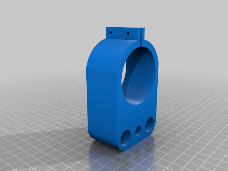 You can find the appropriate extension for your version of Sketchup here. Download the extension, go to Sketchup > Window > Preferences > Extensions > Install Extension to install it.
To export to STL after installing the extension, follow the instructions below:
- Go to Sketchup > Tools > Export to DXF or STL
- Select the desired object to export. If you do not select an object, then the model will be exported completely.
- Select the unit of measurement for the exported object: meters, centimeters, milimeters, inches, feet
- Select the geometry of the exported object: polyface mesh, polylines, triangular mesh, lines, stl
- Select where you prefer to save the exported file.
Attention: if you export a circle with this plug-in, then when you view it in some other programs, you will notice that when you increase it, it consists of short segments.
Blender
- Open File > Export > STL
- Enter file name
- Specify file locations
- Press the Export STL button
Pro ENGINEER
- Open File > Save a Copy
- Select STL type and press OK
- Set Coordinate System Standard
- Select file format Binary
- Set the following parameters Chord Height to 0 (set the minimum allowable Pro/E values)
- Angle Control leave the default
- Enter a file name and press OK
Rhino
- Open the File > Export Selected or File > Save As tabs
- Select objects to export
- Set file type to Stereolithography (*.
 stl)
stl) - Enter file name
- Save file
- In the STL Mesh Export Options window, set the Enter Tolerance to 0.02 mm (0.0008 inches), then click OK.
- Set the file format to Binary
- Uncheck the Uncheck Export Open Objects option
- And press OK again
Solidworks
- Go to File > Save As…
- Set the file type to STL(*.stl)
- Open the Options tab
- Set the output file format to Binary
- Unit: > Millimeters or Inches
- Resolution-Good (Resolution > Fine)
- Press OK
- Enter file name
- Save
SolidWorks Student Design Kit
- Open File > Save As…
- Set file type eDrawings(*.eprt)
- Open the Options tab
- Check the box Allow export to STL for Parts & Assemblies
- Press OK
- Enter file name
- Save file
- Open the file in eDrawings
- Open the tabs File > Save as… > and set the file type to STL (*.
 stl)
stl) - Save file
Rules of thumb
- Export with 0.001 mm chord height and 15 9 angular tolerance0243 o for best results 3D printing .
- Avoid exporting unnecessary large STL files.
Preparing models for 3D printing: Materialize Magics features
3D basics
Software
Author: Kirill Romanov
Author: Kirill Romanov
Materialize Magics: An all-in-one 3D printing program | What is included in the software | Magics RP Base Module Capabilities | Additional modules | Benefits of Magics
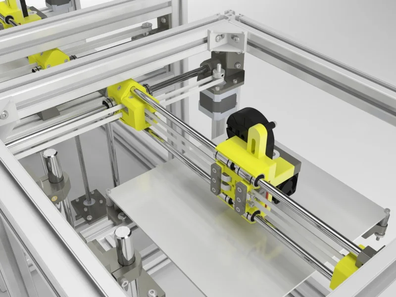
How models are prepared for 3D printing
Additive manufacturing starts with the modeling of objects, which is carried out in various programs such as CATIA, SketchUp, SolidWorks, Inventor, Siemens NX and others. In order to print a product, it is necessary to prepare its digital model, and this process can take up to 32% of the time of the entire additive manufacturing cycle, depending on the technology and complexity of the object.
To manufacture a part on a 3D printer, first of all, you need to get an STL file. To do this, we convert a rigid body to a polygonal model, and then perform the operations of correction, enhancement, editing, platform preparation, nesting, generation of supporting structures, measurements and analysis.
The next stage is slicing (separation into layers), which consists in creating a control program for a 3D printer. The model is divided into layers with a certain step, and on each layer we get a closed contour, along which the extruder or printer's laser beam will pass. Each layer is usually a 2D DXF image.
Applying Materialize Magics Software to the Additive Manufacturing Cycle
Next, the object is printed and undergoes the necessary post-processing. The stages of work from converting to STL to slicing are performed in specialized software, which will be discussed in our review.
Attention! In the context of sanctions, VoxelDance will become a worthy analogue of the software of manufacturers who have left the Russian market.
 These are universal solutions for preparing models for 3D printing at a bargain price. Check out the overview and demonstration of work in the software product.
 Materialize Magics: Universal 3D Printing Software
The most flexible and comprehensive solution for these purposes is offered by Materialize, which has developed the Magics software product for 3D printing professionals. It allows you to create individual layers of components with high speed and accuracy based on 3D CAD data or 3D scan data. The software provides a full cycle of additive manufacturing - from data import (in STL and other formats) and quality analysis to platform preparation and post-processing.
Materialize Magics is unique in that it comes with the widest range of features available today. This is a kind of constructor, flexible and adaptable to almost any task of additive manufacturing. The software works with all types of 3D printers, and many manufacturers are building Magics into their hardware.
What's in the
softwareBase module RP
- Has a wide range of special functions for editing models.
- Works with a large number of import file formats.
- Quickly, accurately and geometrically correct errors in uploaded files.
- Keeps the original color, textures and textures of objects after the "treatment" of the downloaded files, depending on the settings.
- Provides convenient configuration of processes at all stages of preparation for printing.
Additional modules for specific functions
For example, the Import Module allows you to import many different formats; Structures allows you to design and print honeycomb structures and layers; Slice is used to transfer objects at the layer level in CLI, F&S, SLC, SSL formats; Tree Support is a set of supports, and so on.
Let's take a closer look at the capabilities of these software products.
Magics RP
The most important modeling step for a 3D printer is correcting errors. RP allows you to automatically correct errors in polygonal models, such as inverted normals, holes, open boundaries, noise, self-intersections of triangles, overlaps, etc.
Software functions:
- One-click auto-correction of the most common geometry problems;
- a step-by-step fix wizard to selectively fix certain categories of bugs;
- manual patching tools to restore the most difficult areas.
1. Model editing:
- empty parts (walling) to save material, reduce weight and build speed;
- perforation to extract unused material;
- adding thickness to thin walls or modifying a part using the Offset & Extrude tool;
- converting a thin-walled surface to a solid model using Surface to Solid.
A large-scale SLA-printing project for mammoth bones. Emptying the model reduced material costs by 80%
Since some 3D printers have data upload limits, the following functionality is used to lighten the weight of the file:
- reduction of triangles;
- smoothing sharp edges;
- global rebuilding of the polygonal mesh.
2. Marking:
- Easily add text and images (DXF) to parts as markings.
3. Slicing (to separate the model and print it in parts if it does not fit in the printer chamber):
- notched cuts to reinforce the assembly;
- automatic creation of guide pins for assembly.
Using Magics, Nissan Motor Corporation has reduced the time it takes to process a 3D model and model assembly elements by 85%.
4. Boolean operations:
- just like in any CAD, the software makes it possible to perform Boolean operations, and directly in the STL file.
5. Platform preparation:
- platform visualization;
- automatic placement of objects on the platform;
- comparison of the positions of the model by various parameters;
- placement of the model, taking into account surfaces without supporting structures;
- a large library of 3D printers that you can replenish yourself.
6. Import:
- 3D printing software allows you to import polygonal models in all the most common formats - STL, OBJ, PLY, VRML - and many others.
Import Module
Using this module, you can additionally import CAD formats such as CATIA, NX, SolidWorks, while they are immediately converted to an STL file.
Slice Module
Creating a control program for a 3D printer includes features such as:
- preview of each print layer;
- saving settings for each machine;
- construction of a graph of the distribution of layers, which shows the dependence of the height on the area of a given section.
Structures Module
This 3D printer modeling software allows you to create different structures inside the model for:
- reduction in weight, amount of material used and build time;
- giving greater strength compared to the devastated part;
- Prevent warping and build errors during printing by reducing the area/volume that is exposed to heat.
SL Corporation performs 3D printing of mounting fixtures. Due to the creation of structures inside the part, the weight of the product has decreased by 40%
Sinter Module
Specially designed for SLS printing and provides automatic placement of parts in a given build chamber volume:
- maximum use of the volume of the 3D printer building chamber when placing parts;
- creation of boxes for fragile or groups of small parts.
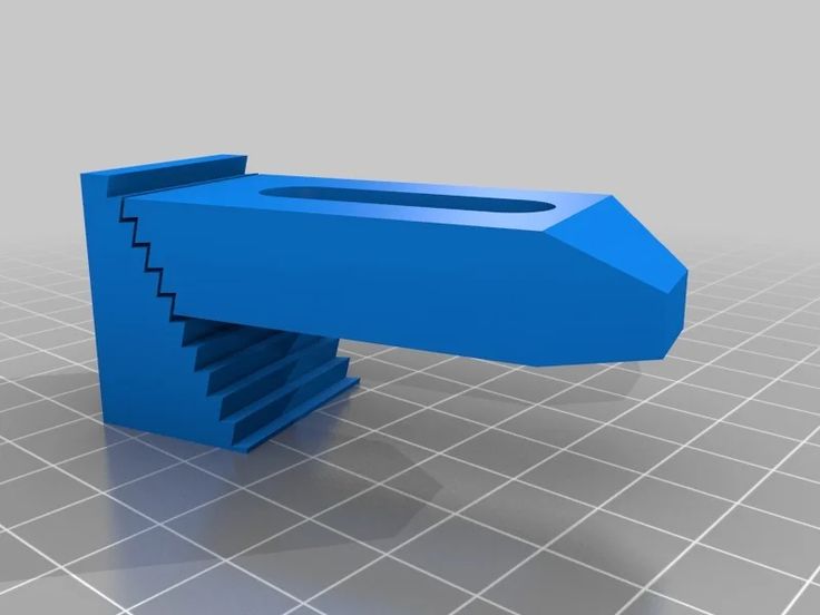
SG Module
Performs the function of building supporting structures for printing complex objects using various technologies (FDM, SLA, DLP):
- when changing the orientation, you can see where the supports will be built in real time;
- the serrated shape ensures the generation of strong yet easily removable supporting structures;
- perforated supports help save time and material;
- you can save a support profile with the specified parameters and use it for other products;
- The list of surfaces allows you to analyze and optimize support if necessary.
Tree Support Module
With the help of this software, tree-like supports are built, i.e. structures with a "trunk" and "branches". Tree Support provides the following benefits:
- ability to build supports in semi-automatic mode;
- improved surface quality by minimizing contact points;
- prevention of deformation of the product due to heat removal;
- easy removal of supporting structures by creating break points;
- lack of powder inside the supports;
- determination of the optimal cross-sectional diameter of the tree support depending on the material.
SG+ Module
A special modeling program for a metal 3D printer allows you to:
- to build three-dimensional supporting structures in order to avoid detachment from the platform and deformation of the product;
- create conical supports in critical places to improve heat dissipation;
- automatically generate angular and tree support.
Read more in the article: Benefits of Materialize Magics when creating supports for 3D printing
Simulation Module
Designed to simulate the printing process with metal and visual display of various mechanical deformations or conduct thermal simulation.
Simulation of risks in 3D printing:
- simulation of mechanical deformations of a part and supports;
- definition of overheating zones;
- compiling the field of internal stresses of the metal on each layer and on the product as a whole;
- definition of zones with high shrinkage;
- visualization of results;
- obtaining a product with compensating dimensions.
The software also evaluates printing risks, such as broken support structures, recoater collisions, shrinkage, overheating, and helps prevent scrap.
Read more in the article: Magics Simulation Review: How to Prevent Risks in Metal 3D Printing
Magics software is also available as a kit for educational institutions.
 The kit contains all the Magics modules and will help schools, universities and educational centers improve the process of teaching additive technologies. A special offer for an educational package includes perpetual licenses for 20 or more seats with annual technical support.
 In addition to Magics, Materialize offers 3D printing programs as separate base modules.
-
3-matic is designed for modeling in STL-format (standard triangulation) and makes it possible to perform topological optimization at the microstructure level, including with the help of many CAE programs.
-
e-Stage enables fully automated generation of support structures and reduced post-processing costs. Creates contact points with minimal area support, making it easier to remove. The software is available in two configurations: for photopolymers (SLA) and metals (SLM).
Benefits of Materialize Magics
3D Printing Software-
Speed, optimization and high reliability of all processes.
-
A set of practical and efficient solutions for preparing platforms, building support structures using any 3D printing technology.
-
Wide functionality for editing models (adding logos, textures, images).
-
Ability to perform complex cuts (for example, with built-in connecting pins), Boolean operations, etc.
-
The presence of an extensive library for almost any equipment with prescribed and customizable parameters.
-
Analysis and correction (quick correction, preparation and optimization of the polygon mesh with the best preservation of texture, color and quality, analysis of possible problems).
-
A wide range of tools for conducting additive manufacturing business processes.
-
Intuitive, easily customizable interface with technical support from the developer in Russian.
Do you have questions? Contact iQB Technologies : our experienced experts will advise you on purchasing Magics, 3D modeling and other aspects of 3D technology.