3D printing connections
How to connect two parts with 3D printed joints and snap fits
Posted By Amandine Richardot on Apr 25, 2018 |
How can you efficiently connect two 3D printed parts? You could glue some components to connect them, but there are other ways to do it, more convenient. Indeed, you can integrate some specific design features directly in your 3D models. These interlocking features will help you drastically reduce assembly time, and designing snap-fits or other kinds of 3D printed joints is not so hard! To learn how to create the best 3D printed joints and snap fits for your parts, follow the tips of our 3D designers from Sculpteo Studio, our 3D design studio specialized in additive manufacturing!
What are 3D printed joints and snap fits?
3D printed joints are all the design features you can insert in your 3D model to connect parts together without using external components (not even glue).
One of the most common kinds of joints for 3D printing is snap fits. These special connections work as follows: a design feature similar to a hook is inserted in another part, where there’s a special hole or space made for it. This is made possible thanks to the fact that this hook is quite flexible and moves while being inserted, and then gets back to its normal position when in the right spot, which blocks it.
3D printed snap-fits and joints are very commonly used to design enclosures, even if it’s far from being their only applications.
Interested in learning more about how to create the best enclosures using the 3D printing process? Read our previous post to make the best enclosure designs!
The benefits of inserting connections directly in your 3D design
Thanks to 3D printing, you can connect your 3D printed parts together with design features that are directly part of your design. What’s the point of using this kind 3D printed joinery? Here are the main benefits you can get from joints specifically designed for 3D printing!
Additive manufacturing makes you save time
First, if you implement 3D printed joints directly in your design, you will drastically reduce assembly time of your objects. For one prototype, that’s already a good start, knowing that accelerating product development is a major priority for businesses. But try to think of mass-production. This gain of time can be extremely precious in order to manufacture your products faster.
Your 3D printed parts can be strong but flexible
3D printing helps you play more easily with wall thickness thanks to the strong but flexible materials you can use with this technology. Indeed, the plastics used for additive manufacturing are particularly suited for the creation of joints such as 3D printed snap-fits which require flexibility, but strength.
Additive manufacturing, for great precision
Additive manufacturing is also particularly precise, often more than injection molding. Indeed, accuracy is good for multiple 3D printing materials. And in the case of 3D printed connections, you need your parts to be perfectly assembled.
Iterate more easily thanks to 3D printing
When you work with injection molding, you first need to create a mold for your part. Thus, if you realize after a first try that something doesn’t quite fit in your joint, you will have to make a whole new mold. It takes time, and it has a cost. With additive manufacturing, you don’t have this issue. If it doesn’t fit, you just need to edit your 3D model, and then 3D print it again.
Which material should you use for your 3D printed joints project?
For this specific post, our 3D designer chose to 3D print all of her parts in HP Multi Jet Fusion Nylon PA12, in its non-dyed version. This is a great choice for your prototyping projects. It is both strong and flexible, and it’s our cheapest material.
For finished goods, with better surface finishes, or if you want a different aspect, you can choose other plastics, as long as they are both strong and flexible. SLS Nylon PA12 can be a great choice for this use. Indeed, SLS 3D printed parts perfectly match these requirements.
On the other hand, very rigid 3D printable materials are not recommended. For instance, metal 3D printing is not really compatible with snap-fit design.
The different types of 3D printed snap-fit connections
Cantilever Snaps-fits
Cantilever snap-fits are the most common kind of snap-fit connections. In this kind of 3D printed snap fit, a protrusion (just like a hook) on one of the parts is inserted in a specific cut-out. Inse it’s inserted, the protrusion bends back, which locks the connection and makes sure it doesn’t move.
Cantilever Snap-Fits, with two different lengths
Cantilever snap-fits can be more or less flexible, depending on their shape. When they are in U-shape, they are extremely flexible, and thus, easier to take off. When they are in an L-shape, they are more rigid, but still quite flexible. Here’s an example of both shapes.
Cantilever snap-fits in U shape on the left and L shape on the right
Here’s a variation with separable cantilevers. They are easier to take off and less visible.
Separable cantilever snap-fits
Annular cantilever snap fits are more robust, but harder to take off.
Annular Cantilever Snap-fits
Last but not least, here are Clips, another kind of cantilever snap joints. They are very hard to take out but very robust.
Long Cantilever snap-fits, also known as Clips
Of course, in all of these cases, you can adjust the shape depending on your need and on your part.
Also, here’s one special tip from our 3D designer. If you need to take off the part quite often, we advise you to implement holes where the protrusion is inserted, it will make it easier to make it move afterward. Moreover, reducing wall thickness (as long as your 3D model is thick enough to be 3D printed) will increase the flexibility of your snap-fit joint.
Annular snap joints
Annular snap joints work just like pen caps. There’s a groove on one part, and another groove, exactly similar but inverted, on the other part. It only works on circular kinds of parts. Are you in need of taking the part out quite often? The deeper the groove, the harder it will be to take out. Thus, working on this parameter of your 3D design will help you. Another interesting feature of annular snap joints is that they can turn around, unlike cantilever snap fit joints.
Annular Snap Joints
Here are some variations of annular snap joints, which are articulated. They can move more or less, depending on the shape of the inserted part.
Annular Snap-joints with Hexagon shape
Annular snap-joints with Sphere shape
Torsion snap joints
Torsion snap joints are very interesting to produce using 3D printing. Indeed, they fully capitalize on the flexible properties of 3D printing materials, and on the fact that they can slightly move, while being strong.
When you push the sink, it makes the bar very slightly turn, which opens the joint. This system is particularly suited for connections of parts you will take out quite often.
Torsion snap-joints
Other types of 3D printed joints
There are other types of 3D printed joints, apart from snap-fit joints. Here are two of our 3D designer’s favorite ones.
Screw joints
Screw joints work exactly like a screw. Thus, you can only use it for round-shaped objects. It is particularly suited for objects that need to be opened very often since it allows for an easy opening. A major advantage is that even if it’s easy to open, it’s still a strong and robust connection.
Screw joints
Gutter
Another very interesting way to create 3D printed joints is to create gutters, just as shown in the following pictures. Here, you just need to make your parts turn until it’s blocked.
Here, our 3D designer slightly increased progressively the height of the plane surface with holes so that the two parts are really blocked. This makes a very strong 3D printed joint.
Gutter joint
Now you’re ready to create your own 3D printed joints and snap-fits for your additive manufacturing project! Do you already know which tool you can use to create your 3D printed snap-fit? Here, you will learn how to choose the best 3D modeling software to create your own STL files, the most commonly used file format for 3D printing!
Your 3D file is now ready, with the best joints for 3D printing? Just print it with our own 3D printers, using our online 3D printing service!
Also, do you want to know more about the multiple applications of additive manufacturing, or get advanced design tips and increase your 3D printing knowledge? You can subscribe to our newsletter! For instance, do you want to get inspired to design and construct your own furniture with this technology? You can read this dedicated blog post! Or, you can also learn on our blog where to download the STL files you need for your project!
3D Printed Joinery: Simplifying Assembly
Joinery is a term usually found in woodworking, referring to the practice of joining two pieces of wood together by geometrically constraining them. Good joinery provides strong connections with little-to-no help from fasteners like nails or screws. Joinery is useful because it ensures a strong connection with a less complicated assembly process. However, it usually involves complicated shapes that take time to design and create, while bolts and screws just require a hole and a mass-manufactured fastener.
A classic T-bridle joint, printed in Onyx
3D printing is in an interesting position as a fabrication method because printing complicated geometry is often no more expensive than printing a block. Instead, FDM printing is limited by material properties and the process of building in layers. Thus designing for 3D printing requires a new mindset, and part of that mindset is leveraging the geometric freedom of a 3D printer to reduce the complexity and cost of the final assembly. One way to do that is to look at joinery invented for wood working and injection molding and apply that to the constraints of 3D printing. In this blog, I discuss leveraging simple joints like dovetails and snap fits to improve your 3D printed joint designs, supplemented by some examples.
Dovetails
A classic dovetail joint
When it comes to constraining two parts, many people think in right angles. And this is efficient, especially when thinking about machining; right angles are generally much easier and faster to make than odd angles, requiring fewer setups and no special bits or indexing tables. To a 3D printer, however, dovetails and straight walls are all the same. With no extra effort, you can constrain another degree of freedom. This comes in handy everywhere, whether you want a sliding assembly or a fastener-less T-joint.
Sliding dovetail box, disassembled
The flared walls and tight tolerances allow this box to slide smoothly
When thinking in angles, bear in mind that the established dovetail shape isn’t the only application. The two-part sliding box shown above accomplishes the same restraint as a dovetail, but looks more like a plate with angled sides. This allows it to slide together with the other half of the box easily, and even includes a little detent at the end to snap it shut. This shape would be very hard to manufacture by most other means, but the Mark Two was able to 3D print joints without supporting materials and achieve a great fit.
Check out our Composites Design Guide
Exploring even further, angled geometry in general can help in 3D printing. For instance, printing a sideways V profile, shown below on the left, can create a constraint that would be difficult to machine, but is trivial to print. Meanwhile, a classic tongue and groove joint, as shown on the right, is hard for most printers to make because of the overhang it creates. This overhang results in a poorly supported bottom face with bad dimensional accuracy, and should be avoided if possible.
Profiles of a sideways V wall (left) and a tongue-and-groove joint (right)
Snap Fits
Snap fits are a commonly used method for cheaply joining injection molded parts. These are good shapes for plastics because they stay within the geometric constraints of mold making and use plastic’s ability to elastically deform and then snap back into shape. Because snap fits are designed for plastic, they are easily adopted for 3D printing…on the XY plane. Most 3D printer users know that objects printed on desktop FDM printers are significantly more susceptible to failure in tension along the Z axis (pointing out of the build plate) than in X and Y, because of the inter-layer boundaries. Since snap fits usually have thin cross-sections (to reduce bending moment of the clip), 3D printed snap fits must be printed “laying down” on the build plate, lest they risk shearing after repeated use.
Diagram of cantilever snap joint, printed in three possible orientations
This diagram shows an exaggerated visualization of the layers of a printed snap fit. When printed upright (pictured at left), the forces that deflect the snap fit also put tension between the layers, making it significantly more likely to break. Printed on its back (pictured at center), a snap fit will definitely be stronger, but still has a shear plane running between the tooth and the arm. Printed laying down on its side (pictured at right), however, the snap fit has no layer boundaries within its cross-section, giving it more predictable strength. And, if the snap fit is big enough, printing it on its side would allow fiber to be routed into the tooth, thereby utilizing the full strength of a Markforged part. This same rule applies for gear teeth, ratchet teeth, and any other protrusion that needs to hold significant load.
Request a free sample part
Bear in mind also that snap fits can take many forms based on application, and that the design and orientation of the snap fit may change based on your project. In particular, snap fits coming out of 3D printer are not constrained by thicknesses or mold shapes, so you can get creative with where you put them (see below). Printers make it quick and easy to prototype, so try a few geometries before settling on the final shape.
A flush snap fit mortise a ndtenon joint
Cross section of flush snap fit mortise and tenon
Putting it Together: Phone Holder
To exhibit sliding fits and snap mechanisms, I designed this cell phone holder that hooks over the hood of the Mark Two and holds any cell phone between 2.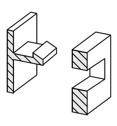 5 and 4 inches wide, so that an operator could take a time lapse video or monitor a sensitive print.
The phone holder with a phone in its grasp
This phone holder has just three parts, two interfaces. One of those interfaces is a twisting joint that acts as a hinge. Though it doesn’t look much like a dovetail, it serves the same purpose: it allows for an easily printable sliding fit, thanks to complementary angles.
Disassembled phone holder (left) and hook (right)
Rotating joint locking into place
The other interface works like a linear ratchet with angled walls (to keep them from slipping apart) and teeth to set the width of the holder. This would be a very difficult interface to machine make by most other means, but it was quite easy and quick to print!
The teeth of the linear ratchet with the corresponding face (right)
The linear ratchet for adjusting to phone width, engaged
The phone case in use, watching a Mark Two print
A Note on Tolerances
As with anything, joinery requires designing in your tolerances. On the Mark Two composite 3D printer, for most general purposes, a .08mm gap between each wall (.16mm diametrically) is enough to allow two pieces to consistently achieve a sliding fit. If one of your surfaces is held up by support material, try bumping up the gap to .15mm or so. Of course, 3D printed parts tend to vary widely, so make sure to unit test and prototype to achieve the fit you want.
This is just one small example of how designing with joinery in mind can lead to designs that are simpler and better-fit for your 3D printer. As you find good joints for printing, tweet at us @MarkForged to share your designs!
3D Printer Threads and Thread Inserts for Plastic
At Formlabs, we design various functional parts for printing on our stereolithographic (SLA) 3D printers such as the Form 3. These parts include prototypes used for our own R&D, clamps and fasteners to be used on our production lines, models to check the design before casting the final product in the appropriate material, such as nylon. nine0003
Regardless of the application, we often need to connect 3D printed components with screws and threaded fasteners. As the catalog of versatile and reliable engineering polymers grows, the differences between "imitation" prototypes and functional prototypes diminish.
This article is a guide to threading and threading 3D parts with a 3D printer. There are many ways to connect multiple 3D printed parts together, but if you need the ability to repeatedly connect and disconnect components and secure mechanical fastening, there is no real substitute for metal screws. nine0003
Do you like to see everything with your own eyes? Watch a video about 3D printing threaded connections and threaded inserts for 3D plastic parts.
White Paper
Download our white paper on stereolithography to find out how SLA printing works, why thousands of professionals use it today, and how this 3D printing technology can be useful in your work.
Download white paper
Let's take a look at some of the threading options for 3D parts we've put together based on years of Formlabs experience and your suggestions.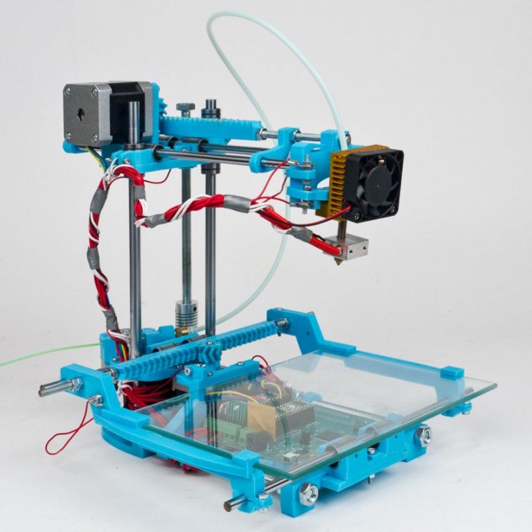 We've ranked these options, starting with the one we think is the best, with the pros and cons of each option for different use cases. nine0003
Experience Formlabs print quality first hand. We will send a free 3D printing sample directly to your office.
Request a free sample
Benefits: Strongly connects 3D printed parts without the use of glue. The metal threads are durable and reusable.
Drawbacks: Inserts may loosen as temperature rises.
3D print a sleeve blank with a depth and diameter that matches the insert specifications. Rinse with isopropyl alcohol (IPA) and allow to dry without final polymerization. Insert the insert into the sleeve with a screwdriver and use the screw to secure it completely into the plastic. Then finish curing the part to reduce the creep effect and fix the insert in the plastic even better. Performing this step last reduces the chance that the insert will break the sleeve when screwed in.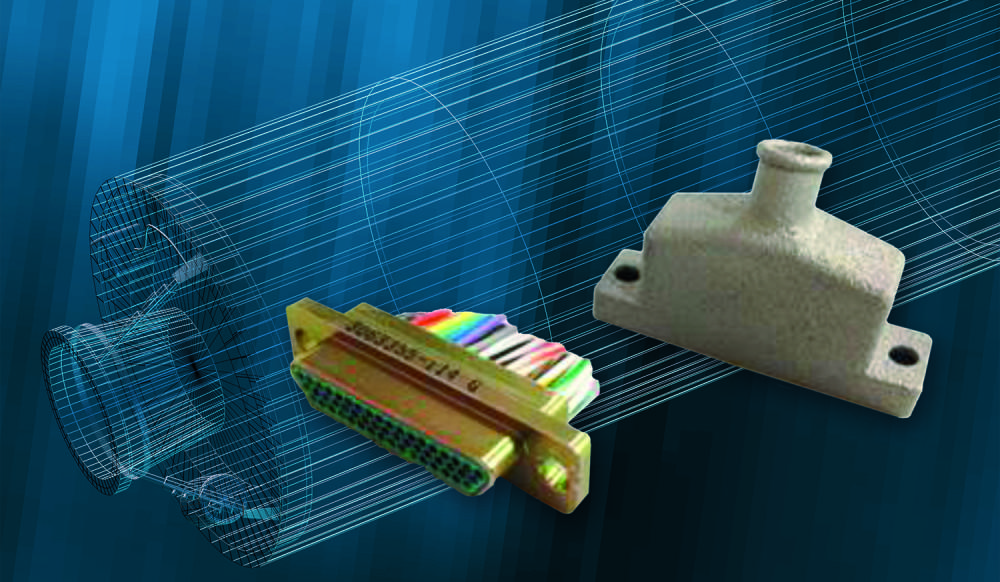 nine0003
Benefits: Connects 3D printed parts very securely. The metal threads are durable and reusable.
Cons: Adhesive required (don't try to use a soldering iron!).
Threaded inserts with heat setting are designed for installation in thermoplastics using a soldering iron with a soldering tip. They can be used in acrylic models and Fused Deposition Models (FDM), but cannot be installed in SLA photopolymer parts, which bend but do not melt when heated.
Check out our detailed guide comparing FDM vs. SLA 3D printers to see how they differ in terms of print quality, materials, application, workflow, speed, cost, and more.
However, the notches and ridges on the heat set inserts make them a very effective thread fastener if you bond them with a two part epoxy or cyanoacrylate adhesive. Determine the bushing size by the largest diameter of the insert and apply some adhesive before installation.
For best results, the part must be completely dry and cured. nine0003
Benefits: Nuts are easy to match to any required screw size.
Drawbacks: Side nut slots can eliminate the need for glue, but can make it harder to support the model during printing.
Adding a hexagon socket to the nut press-fit end creates a reusable strong metal-to-metal connection. To increase the twisting force, you can choose a square nut. This nut can also be plastic or have blocking elements. If necessary, a drop of cyanoacrylate glue will help hold the nut in place, but if the design includes a side socket, there is no need for glue. Use a 0.1 mm offset around the press-in nut and clearance around the screw itself. nine0003
Benefits: Prototyping uses the same metal products as mass-produced injection molded parts. Sleeve blanks made from Tough (and Durable) polymer are unlikely to crack if you follow the screw manufacturer's sleeve design guidelines.
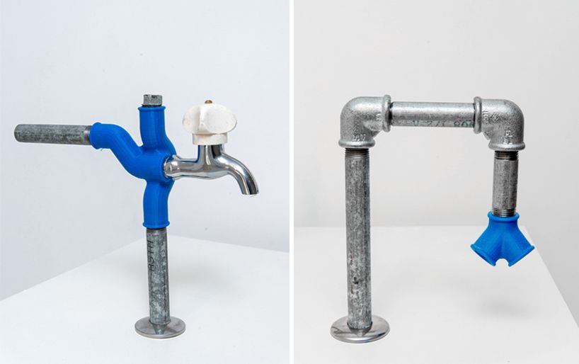
Disadvantages: The screws will hold tight, but the threads will not be as resistant to repeated use as metal threads. Standard resins can be used, but the bushing is more likely to crack. nine0003
Follow manufacturer's recommendations for core sizes and print with high impact engineering resins (such as our Tough Resin and Durable Resin). Before using the screws, complete the final curing. If you are prototyping an injection molded part that will use tapping or tapping screws in its final assembly, this is a good option for testing.
Benefits: No need to buy special plastic screws. nine0003
Disadvantages: The screws will hold tight, but the threads will not be as resistant to repeated use as metal threads.
We have tested screws in our Tough Resin product and found that their use is identical to that of threading screws designed for plastics. The size of the hole diameter of the threaded bushing must be in the range between the main (threaded) diameter of the screw and the inner diameter. The screw shown is a #8 screw in a 0.16" diameter hole. nine0003
Benefits: Can be used for prototyping large and custom threaded designs.
Disadvantages: Not a durable or reusable fastening solution, especially for smaller thread sizes.
3D printed threads from standard resins are better than Tough Resins because they are much harder. 3D printed threads remain relatively brittle, depending on the size of the thread, and are not recommended if the fastening system is to be used continuously and repeatedly. nine0003
Thread sizes ¼-20 or larger are generally functional without the need for post-processing. For smaller screws, the threads must be modified to provide better fastening. For example, printing a round thread profile (on a screw and a nut) and using a 0.1mm offset results in a better thread fit and improved wear characteristics. For all screw sizes, it is best to orient the parts so that the supporting structures do not touch the threads.
White Paper
Tolerance and fit design reduces post-processing time and simplifies assembly, as well as reduces material costs per iteration.
Learn more
We hope this guide has provided you with useful information about the mechanical mounting options that can be used for 3D printed components! If you are interested in seeing the model we use for testing, please download the STL file.
Download STL file
Parts mentioned in this manual can be ordered from McMaster using the links below:
- M3 insert with heat setting for plastic
- Brass M3 screw-in insert for plastic
- Galvanized steel hex nut M3
- Galvanized steel hex nut M4
- Threading screw 4-20 for plastic
Want to try Tough Resin, Durable Resin or any other Formlabs 3D printing material in action? Request a free sample! nine0003
Request a free print sample SLA
3D printing - threads and screws
First things first: what is the difference between a screw and a thread?
A screw is a fastener used to form a connection that can later be dismantled, while the thread is the main fastener of the screw. In this case, the thread is not only used for screws; they are also present on pipes, in linear drives, worm gears and many other devices. nine0003
The common feature of all threads is the way they are formed. Each thread is a continuous spiral groove of a certain cross section, made on the outer or inner side of the cylindrical surface.
In most cases, the cross section or shape is triangular or trapezoidal. Triangular thread forms are primarily used for fasteners (screws), while trapezoidal thread forms, varieties of square threads, are used for power transmission and linear drives on lead screws. To keep things simple, this article only covers triangular shaped threads, but everything applies to both types. nine0003
A further level of categorization distinguishes metric threads from inch threads. The former are mainly used in Europe and Asia, while the latter are used in America and the UK. To the untrained eye, they look the same, but the difference exists in the shape of the triangle and the pitch of the spiral curve.
In this article, we will cover the basics of designing and 3D printing screws and threads.
Basic terms
There are a few terms and concepts that you should be familiar with before you start designing a thread. nine0003
External or internal thread : External or external thread exits the cylindrical surface. The female thread is cut on the inner cylindrical surface. For example, bolts have external threads, while nuts have internal threads.
Thread axis : line through the center of the cylinder on which the thread is to be formed.
Base : the bottom of the groove that runs around the body of the thread.
Comb : The highest point of the thread profile. nine0003
Large diameter : The diameter of a cylinder enclosing the top of an external thread or the base of an internal thread. This cylinder is concentric with the axis of the thread.
Minor Diameter : The diameter of a cylinder enclosing the root of a thread on an external thread or the crest of an internal thread. This cylinder is concentric to the thread axis and large diameter. The smaller diameter is also known as the drill diameter when handling internal threads.
Pitch : distance between equivalent points on adjacent threads. For example, the distance between two adjacent crests of a triangular thread. nine0003
Metric thread: The "M" designation of a metric thread indicates the nominal outside diameter of the thread in millimeters. For example, an M5 thread has a nominal outer diameter of 5 mm. For external threads, the nominal outside diameter is equivalent to the major diameter. For internal threads, the nominal outside diameter can be determined by measuring the minor diameter and referring to the metric thread table.
Inch threads: Inch threads are designated using a number of standards, including the Unified Thread Standard (UTS), which basically refers to standard thread sizes as numbers (eg #4). The two most important measurements in UTS are the major or minor diameter of external or internal threads, respectively, and threads per inch (TPI). nine0003
Thread Modeling
Let's look at the process of designing external and internal threads using Fusion 360, which provides a simplified threading feature.
Other CAD programs have tools of varying degrees of similarity. It is important to understand the basics presented in the previous section. With this knowledge, you will be able to use any available modeling tool for 3D modeling.
Let's start with the outer thread of the bolt.
External thread
- Draw a circle with a diameter equal to the largest diameter of the desired thread.
- Create a cylinder by extruding a circle to the desired thread length.
- Go to "Create" and select the "Thread" option.
- Select the newly created cylinder. Make sure "Modeled" is checked. Set the thread type and other thread options. Click OK.
That's it. You have an external thread! To make a good bolt out of it, you need to attach it to the head to your liking. nine0003
Now let's create a nut with an internal thread.
Internal thread
- Create a hexagon. For the purposes of this tutorial, just make sure it's larger than the carving you want to create.
- Press it out to the desired height.
- Make a hole in the center by selecting the "Hole" option from the "Create" menu. The hole diameter must match the largest thread diameter.
- Select the inner surface of the newly created hole, go to "Create" and select the "Thread" option. nine0003
- Don't forget to check the "Modeled" option. Set the thread size and other parameters. Click OK.
That's it. Your first carvings are ready for 3D printing!
Tips for 3D Printing Threaded Parts
This may seem like a simple task at first glance, but printing threads is not always easy, especially if you need small diameters.
Assume you are using a 0.4 mm nozzle and a 0.2 mm layer height. With this setting, the smallest pitch you can achieve during 3D printing is likely to be around 0.5mm (give or take 0.1mm). This pitch is suitable for M3 threads and you should have no problem trying to print an internal thread on a relatively large part. This is because your threads will have enough time to cool while the nozzle is in a different location. nine0003
Things get interesting if you need an external thread, for example on a screw or bolt. In this case, the nozzle has nowhere else to go, which means that you will probably need additional cooling. Check your 3D printer before you decide to print a lot of thin external threads.
One of the most practical options before starting thread printing is the M10 3D Printed Thread Test. Thanks to this special 3D model, you will be able to check exactly what your 3D printer is capable of. nine0003
Settings when 3D printing parts with threads
Below are some general guidelines for setting up your 3D printer when printing threads.
- Make sure your 3D printer is properly calibrated. Extruder calibration is also important.
- Always try to print threads vertically. For best results, the thread axes should be perpendicular to your 3D printer table.
- Print without the calipers, or at least make sure they don't go inside the threads. Otherwise, removing them and maintaining functionality can be a real problem, especially with internal threads. nine0003
- If possible, use at least 4 vertical layers or vertical walls at least 2 mm thick. This will ensure the strength of the thread.
- Try to set the filling density to at least 25%.
- Layer height is an important parameter when 3D printing threads. For smooth operation, the layers should be as thin as possible. As a guideline, threads larger than M12 or 1/2" can be successfully printed at 0.2mm, while smaller threads should be printed at thinner layers. nine0003
Resume
Even if your first test fails, don't despair! Here are some final tips for 3D printing threads:
- Even if you manage to print beautiful external threads smaller than M6 (6mm in diameter), think twice before using it for heavy duty use.