3D printed joinery
3D Printed Joinery: Simplifying Assembly
Joinery is a term usually found in woodworking, referring to the practice of joining two pieces of wood together by geometrically constraining them. Good joinery provides strong connections with little-to-no help from fasteners like nails or screws. Joinery is useful because it ensures a strong connection with a less complicated assembly process. However, it usually involves complicated shapes that take time to design and create, while bolts and screws just require a hole and a mass-manufactured fastener.
A classic T-bridle joint, printed in Onyx
3D printing is in an interesting position as a fabrication method because printing complicated geometry is often no more expensive than printing a block. Instead, FDM printing is limited by material properties and the process of building in layers. Thus designing for 3D printing requires a new mindset, and part of that mindset is leveraging the geometric freedom of a 3D printer to reduce the complexity and cost of the final assembly. One way to do that is to look at joinery invented for wood working and injection molding and apply that to the constraints of 3D printing. In this blog, I discuss leveraging simple joints like dovetails and snap fits to improve your 3D printed joint designs, supplemented by some examples.
Dovetails
A classic dovetail joint
When it comes to constraining two parts, many people think in right angles. And this is efficient, especially when thinking about machining; right angles are generally much easier and faster to make than odd angles, requiring fewer setups and no special bits or indexing tables. To a 3D printer, however, dovetails and straight walls are all the same. With no extra effort, you can constrain another degree of freedom. This comes in handy everywhere, whether you want a sliding assembly or a fastener-less T-joint.
Sliding dovetail box, disassembled
The flared walls and tight tolerances allow this box to slide smoothly
When thinking in angles, bear in mind that the established dovetail shape isn’t the only application.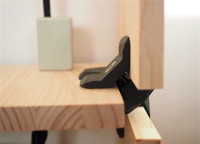 The two-part sliding box shown above accomplishes the same restraint as a dovetail, but looks more like a plate with angled sides. This allows it to slide together with the other half of the box easily, and even includes a little detent at the end to snap it shut. This shape would be very hard to manufacture by most other means, but the Mark Two was able to 3D print joints without supporting materials and achieve a great fit.
Check out our Composites Design Guide
Exploring even further, angled geometry in general can help in 3D printing. For instance, printing a sideways V profile, shown below on the left, can create a constraint that would be difficult to machine, but is trivial to print. Meanwhile, a classic tongue and groove joint, as shown on the right, is hard for most printers to make because of the overhang it creates. This overhang results in a poorly supported bottom face with bad dimensional accuracy, and should be avoided if possible.
Profiles of a sideways V wall (left) and a tongue-and-groove joint (right)
Snap Fits
Snap fits are a commonly used method for cheaply joining injection molded parts.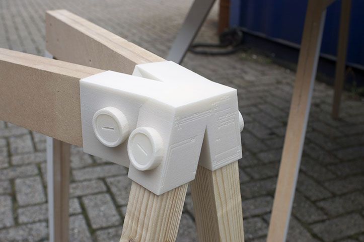 These are good shapes for plastics because they stay within the geometric constraints of mold making and use plastic’s ability to elastically deform and then snap back into shape. Because snap fits are designed for plastic, they are easily adopted for 3D printing…on the XY plane. Most 3D printer users know that objects printed on desktop FDM printers are significantly more susceptible to failure in tension along the Z axis (pointing out of the build plate) than in X and Y, because of the inter-layer boundaries. Since snap fits usually have thin cross-sections (to reduce bending moment of the clip), 3D printed snap fits must be printed “laying down” on the build plate, lest they risk shearing after repeated use.
Diagram of cantilever snap joint, printed in three possible orientations
This diagram shows an exaggerated visualization of the layers of a printed snap fit. When printed upright (pictured at left), the forces that deflect the snap fit also put tension between the layers, making it significantly more likely to break.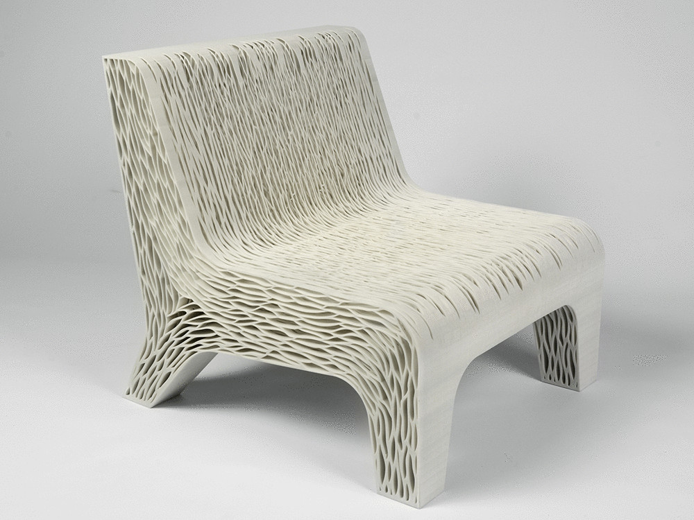 Printed on its back (pictured at center), a snap fit will definitely be stronger, but still has a shear plane running between the tooth and the arm. Printed laying down on its side (pictured at right), however, the snap fit has no layer boundaries within its cross-section, giving it more predictable strength. And, if the snap fit is big enough, printing it on its side would allow fiber to be routed into the tooth, thereby utilizing the full strength of a Markforged part. This same rule applies for gear teeth, ratchet teeth, and any other protrusion that needs to hold significant load.
Request a free sample part
Bear in mind also that snap fits can take many forms based on application, and that the design and orientation of the snap fit may change based on your project. In particular, snap fits coming out of 3D printer are not constrained by thicknesses or mold shapes, so you can get creative with where you put them (see below). Printers make it quick and easy to prototype, so try a few geometries before settling on the final shape.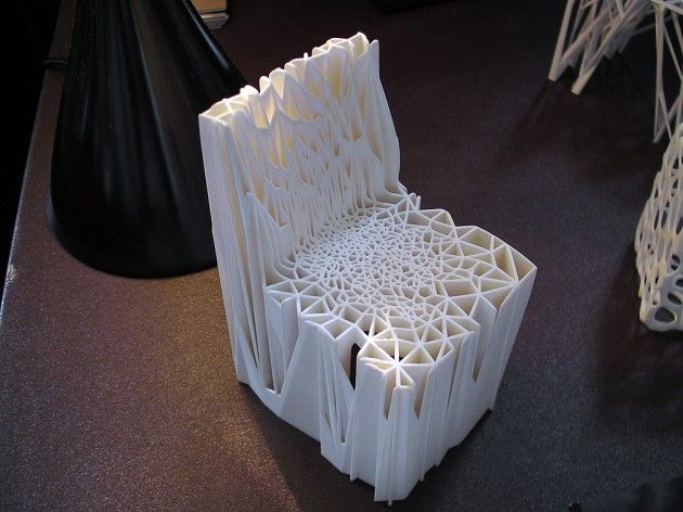
A flush snap fit mortise a ndtenon joint
Cross section of flush snap fit mortise and tenon
Putting it Together: Phone Holder
To exhibit sliding fits and snap mechanisms, I designed this cell phone holder that hooks over the hood of the Mark Two and holds any cell phone between 2.5 and 4 inches wide, so that an operator could take a time lapse video or monitor a sensitive print.
The phone holder with a phone in its grasp
This phone holder has just three parts, two interfaces. One of those interfaces is a twisting joint that acts as a hinge. Though it doesn’t look much like a dovetail, it serves the same purpose: it allows for an easily printable sliding fit, thanks to complementary angles.
Disassembled phone holder (left) and hook (right)
Rotating joint locking into place
The other interface works like a linear ratchet with angled walls (to keep them from slipping apart) and teeth to set the width of the holder. This would be a very difficult interface to machine make by most other means, but it was quite easy and quick to print!
The teeth of the linear ratchet with the corresponding face (right)
The linear ratchet for adjusting to phone width, engaged
The phone case in use, watching a Mark Two print
A Note on Tolerances
As with anything, joinery requires designing in your tolerances.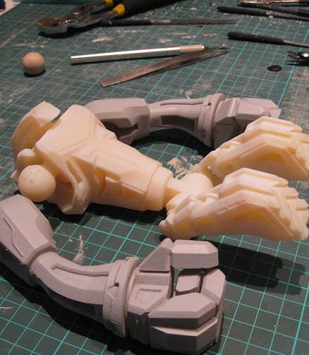 On the Mark Two composite 3D printer, for most general purposes, a .08mm gap between each wall (.16mm diametrically) is enough to allow two pieces to consistently achieve a sliding fit. If one of your surfaces is held up by support material, try bumping up the gap to .15mm or so. Of course, 3D printed parts tend to vary widely, so make sure to unit test and prototype to achieve the fit you want.
This is just one small example of how designing with joinery in mind can lead to designs that are simpler and better-fit for your 3D printer. As you find good joints for printing, tweet at us @MarkForged to share your designs!
3D Printing Joints
- 3D printing press fit parts
- 3D printed joinery
- Snap-fit joints for plastics
- Snap-fit design manual
- Buckle example
- 3D Printed Captured Nuts
- Fasteners and 3D printed parts
Sliding Fit Assembly – Applying traditional woodworking joinery to 3D printed parts.
- 3D guide to Joinery (twitter)
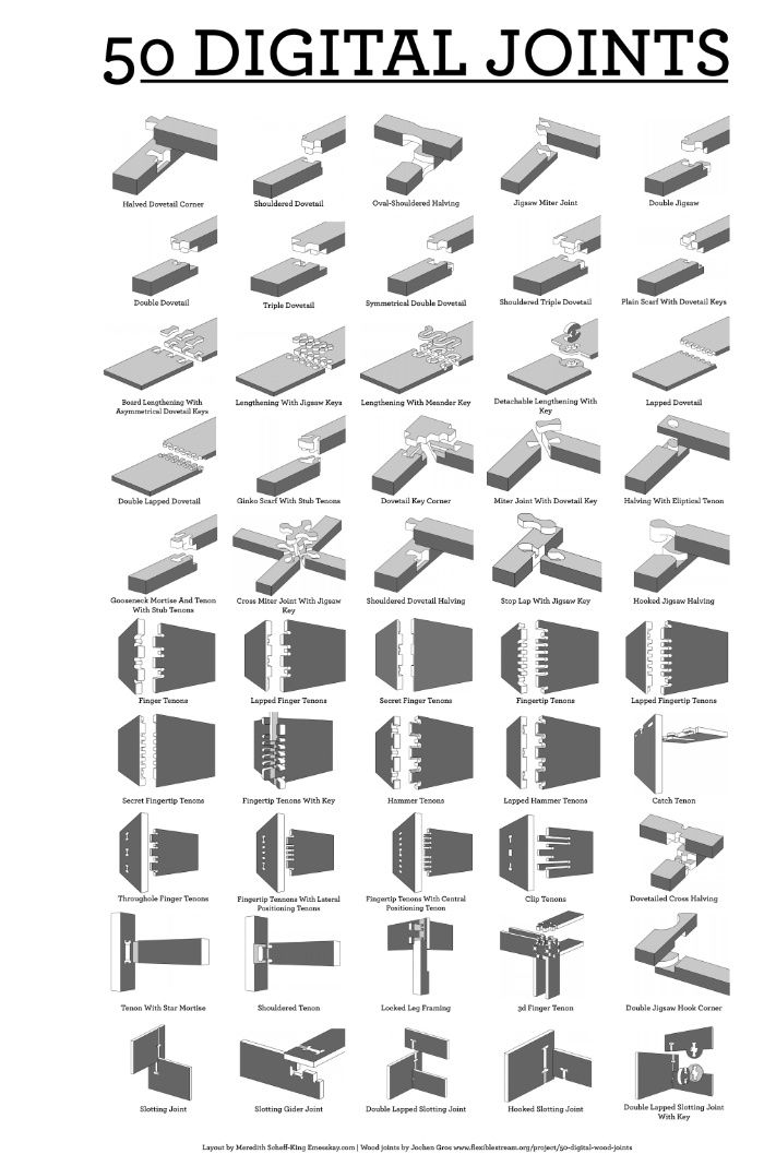
- 50 Digital wood joints
Press-Fit Assembly – Using the friction between two components to hold something in place. A good example for this are lego bricks. They have such a precise tolerance that pieces can snap and come apart with no problems.
Snap-Fit Assembly
Cantilever Snap joints – are the most common – Typically, a semi-flexible cantilevering hook is deflected slightly as it is inserted into a hole or past a latch plate. As the hook passes the edge of the hole, the cantilever beam returns to its original shape.
Annular snap joints – Great for circular applications – Classic examples of ASJs include ballpoint pens with snap-on caps, and the child-resistant cap on Tylenol bottles. One piece is more flexible than the other – in this case when you’re using the same material, that means one piece is thinner and therefore more flexible.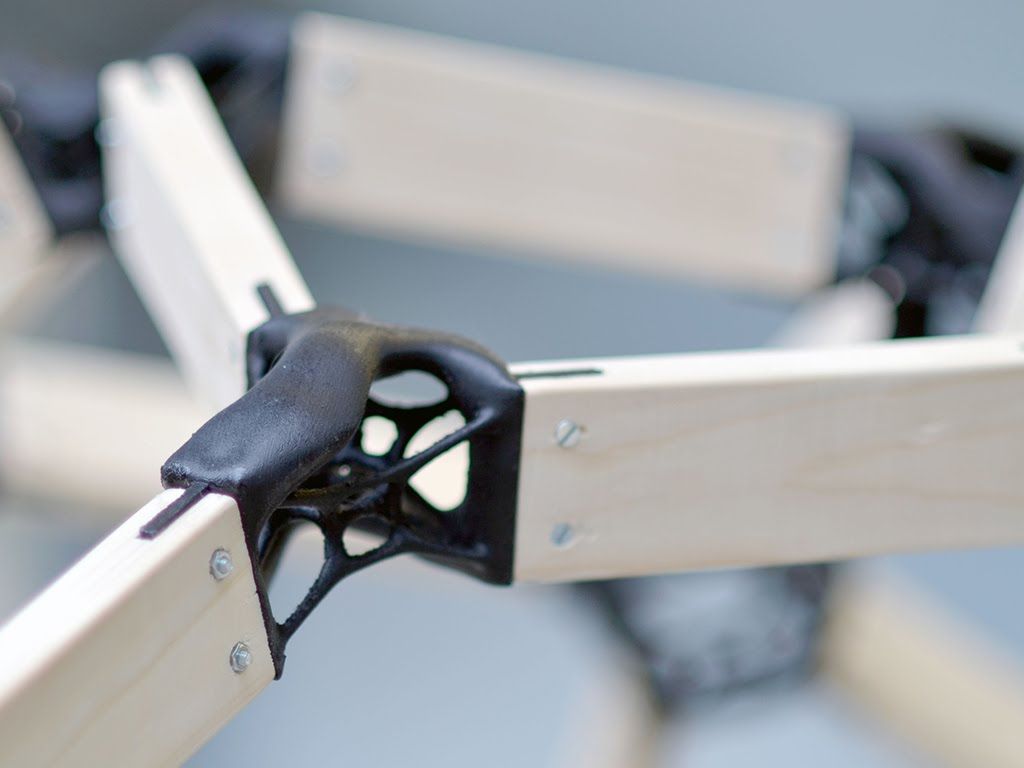
Ball Joints
- Geodesic Dome Joints
Hinges - Snap fit pivots - A good way to print a hinged pivot point. One component uses a protruding annular ball joint. The protrusion is split in half. When the component is being inserted, this gap allows the two halves to deflect and squeeze together. Once the piece is through the hole, pressure is released and the ball expands again to hold the piece in place.
http://www.thingiverse.com/thing:59332
http://www.caddedge.com/stratasys/3d-printing-blog/3d-printing-living-hinge-protoytpes
Kinematics by n-e-r-v-o-u-s http://www.thingiverse.com/thing:195497
1. Experiment with clearance sizes
Usually when fitting two parts together and printing on a desktop FDM printer, the male and female parts of the joint must have a certain clearance between to account for material tolerance. This clearance can vary anywhere from 0.1mm – 0.3mm depending on the printer resolution, material, speed, and more.
2. Test early and often
It’s good to test your connections to find the right tolerance. To avoid wasting time and material, print only the parts you are trying to test instead of the entire model.
3. Building up snaps in the Z-layer has the least amount of strength
Try to avoid printing your snaps in the Z direction (built up from the print bed vertically), they are much weaker than parts printed in the x/y direction.
4. Be careful with scaling
It is always best to model your parts at the right scale. But when you do need to scale a model with connecting parts, it will require you to readjust your tolerances.
Self Threading Screws
This is a great technique for a quick and dirty prototype. Using self tapping screws is quick, cheap and requires minimal design efforts.
Custom Designed Threads in Your 3D Model
If you are using something with large threads, it is best to design them since trying to self tap would require a huge effort. This is only advised for large components (when printing on desktop FDM printers) – the resolution is not adequate for small machined components.
Captive Nut
A great technique for fastening is designing an inset in your model to hold a hex nut. This is great when you want to use machined bolts. It’s important to use your calipers to get exact dimensions and give enough tolerance for fitting your hex nut.
Using high heat to melt metal threaded hardware into your 3D print. The inside of this is nicely threaded for precise machined screws while the outside is roughed with gripping pattern. When it’s melted into the plastic, it will grip nicely and fit snugly when the plastic cools down around it.
How to:
- Get a crappy soldering iron (not one of nice working ones from the BTU lab)
- Heat your iron to low and preheat the threaded insert.
 This should only take a few seconds.
 - Align and place the insert on your model (use some tweezers)
- Use the tip of the iron and carefully push the insert into the plastic using little pressure. Once the insert is aligned flat with the top surface of the plastic, remove your iron.
Pro tip: practice on a test print first!!!
90,000 use of 3D printing in the creation of furniture and interior items.With the advent of 3D printers, many advanced designers tried to use 3D technologies to create furniture and interior elements, but the first attempts were more experimental.
It has only recently become a real business idea with the advent of affordable professional printers that designers and small businesses can afford.
Janne Kitanen, a digital sculptor, has pioneered the use of 3D hardware for design creation, creating complex geometric objects with incredible designs, from exclusive platform shoes to chairs and even ping-pong tables.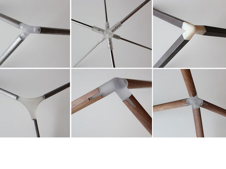 nine0003
Despite the space cost (by the standards of a simple layman), Janne's products are sold out like hot cakes.
The cost of this sofa is $100,000
The main advantages of using 3D printing in this area are:
- new opportunities in design solutions;
- implementation of complex exclusive projects;
- cost is lower compared to traditional production methods.
Let's tell you about 3 designers who use Raise3D 3D printers to create interior and furniture items. nine0003
Wanhao Chai - designer and owner of Yujia Metal Science
Yujia Metal Science creates exclusive metal furniture, and Raise3D N2 is used to optimize production processes.
Wanhao Chai says: “The 3D printer can improve efficiency and save labor costs. Products become clear visually already at the prototyping stage, you can see all the details and quickly make adjustments.»
Sofa printed on Raise3D N2
Yujia Metal Science creates metal household items such as partitions, doors, windows, furniture, wine cabinets, metal decorations and other interior items.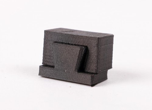
Positioning itself as a boutique designer furniture and exclusive production, Yujia operates in a narrowly segmented direction - the manufacture of furniture and custom-made interior items.
Yujia Metal Science turned to 3D printing to solve the main problem - to increase
production speed and frequency of new products.
Prior to using 3D printers, Yujia ordered very expensive wooden prototypes
to check and match models. Before making the steel version, this process was repeated many times. Many factories do not welcome this format of cooperation with small-scale production, considering it not rational to spend time on the production of single prototypes.
Therefore, Yujia often found themselves in a difficult situation and were rejected by companies due to
small orders.
Using Raise3D 3D printers, the company has been able to:
- Reduce production time by using 3D printers, and by sharing prototype printing across multiple printers.
- Reduce costs by reducing labor required and using cheaper materials for prototypes.
- Transfer the production of prototypes and products entirely to your own production. Thanks to this, they got rid of the extra costs and uncertainty that were inevitable when working with outsourcing companies. nine0018
- Create the largest and most complex versions of your designs thanks to the large printable area and high precision of Raise3D.
Production process:
Prototyping requires only product drawings, a slicer, printing plastic and Raise3D N2 printers. At the beginning, the required file is converted to STL, then the print preview is used to minimize the number of supports and optimize all layers, layout of elements, and the appearance of the model. nine0003
The purpose of printing the first model is to see the appearance of the structure. Using the printed prototype, the designer can physically interact with it, see all the nuances and shortcomings, decide on changes and quickly correct the model.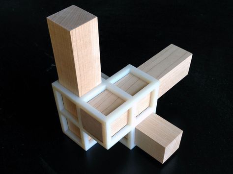
Metal parts and legs will be used in the final chair design.
As a result of the use of 3D printers achieved:
- 91.67% reduction in total production time
- 75% reduction in working time
- 99.17% reduction in prototype costs
Marco Rubini, Italian architect and designer.
Prints furniture prototypes on the Raise3D N2 Dual Plus.
Marco founded his own design studio in 1992. His main areas of activity are design development and consulting in the field of architecture. It has always been important for Marco to offer his customers customized solutions, which N2 Plus is currently helping him with. nine0003
He uses Raise3D to print prototypes and original pieces of furniture in 1:1 scale.
What Marco values most about the 3D printer is its endurance and durability, seeing Raise3D as a workhorse.
Corey Zwerlin (Still Alive Lights LLC) – 3D printing of lighting fixtures.
Corey designs designer shades for LED lights (including solar panels).
On the Raise3D N2 Plus, he prints shades in the shape of animals, flowers and more. To achieve maximum transparency and the best light transmission, Corey adjusts the print settings to the smallest thickness of the model. For his creations, he uses ordinary PLA plastic. nine0003
Currently, 3D printing allows you to create complex objects of unusual shape, the production of which by other methods is the most expensive and difficult to implement. Additive technologies increase productivity and reduce material and labor costs, which is why many companies are already using 3D printing and 3D scanning to produce furniture and interior items.
Do you have interesting stories of using Raise3D 3D printers for business or personal use? We will be glad if you share with us! nine0012
Follow us on social. networks to keep abreast of the latest events:
Facebook Vkontakte YouTube Tsvetnoy Mir team
www.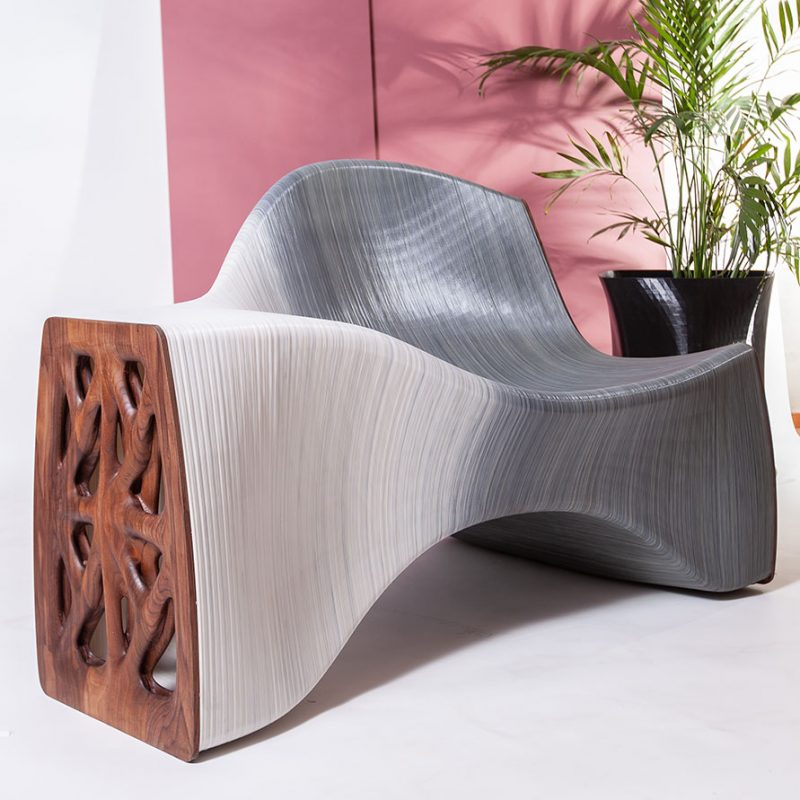 cvetmir3d.ru
Scientists Develop Self-Assembly Furniture Using a 3D Printer / Sudo Null IT News
Israeli scientists have unveiled the next generation of self-assembly furniture flat-pack technology. According to them, 3D-printed wooden parts can be adapted for self-assembly into complex shapes, such as beds and wardrobes. nine0003
Usually furniture parts are made by sawing, carving or pressing. However, scientists at the Hebrew University in Jerusalem took a different path. They used a process where the wood changes shape and texture as it dries.
A few years ago, researchers came up with an eco-friendly water-based ink made from microparticles of wood waste. "Wood flour" is mixed with cellulose nanocrystals and xyloglucan, which are vegetable binders. Scientists have started using ink in a 3D printer. nine0003
They recently discovered that how the ink is applied dictates how the product behaves as moisture evaporates. For example, a flat disc printed as a series of concentric circles dries and shrinks to form a saddle-shaped structure reminiscent of Pringles potato chips. The disc, printed as a series of rays emanating from a central point, turns into a domed or cone-shaped structure. The final shape can also be controlled by adjusting the print speed. nine0003
Shrinkage occurs perpendicular to the wood fibers in the ink, and the print speed changes the degree of their alignment. A slower speed leaves the particles more randomly oriented, so shrinkage occurs in all directions. Faster printing evens them out and the shrinkage becomes more directional.
Scientists have learned to program the speed of printing and its trajectory to obtain various final forms. So, if you add two rectangles printed in different orientations, after drying, you get a spiral. nine0003
Researchers have also shown that they can program the print path, speed, and stacking to control a specific direction of shape change, such as spiraling a rectangle clockwise or counterclockwise.
Further refinement will allow the team to combine seats, domes, spirals and other design items to create objects with complex final shapes, such as a chair.


