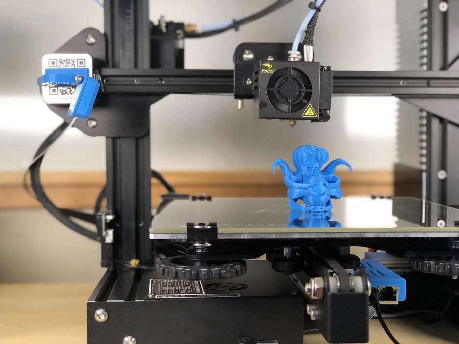
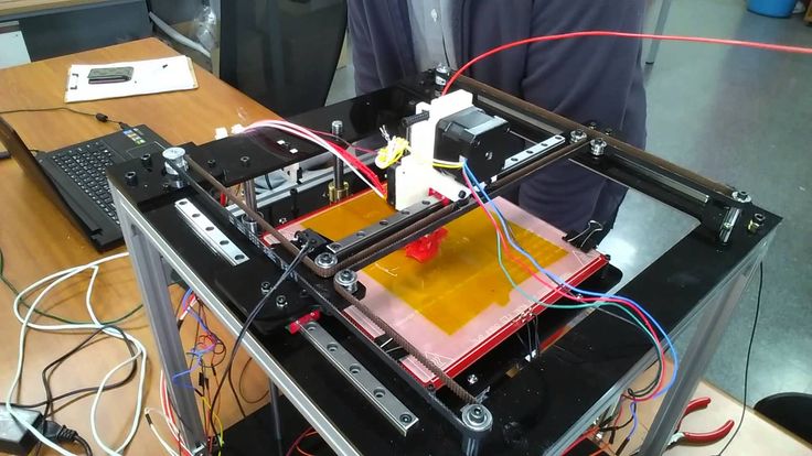
3D print solder stencil
Printing Solder Paste Stencils on an SLA Printer – mind.dump()
3D printing, Electronics
| Jan Mrázek
Share via
A few months ago there was a tweet discussing printing solder paste stencils on a 3D printer. Someone suggested we should try it on an SLA printer. After two months I did the experiment.
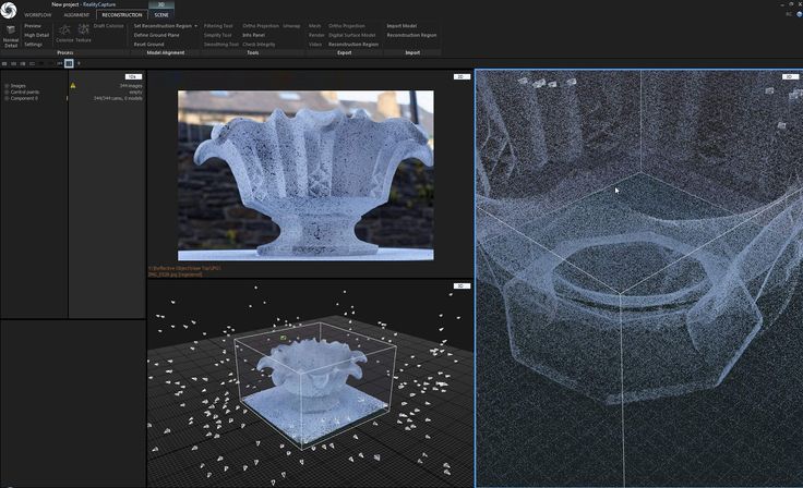
First of all, I struggled a little to get the 3D model of the stencil. There is a service https://solder-stencil.me/ which is supposed to generate the models of the stencils from gerber files. Unfortunately, when I uploaded the gerbers of my board, the model I got was completely broken. So I decided to write a custom tool. The easiest way was to use OpenSCAD (and finally an opportunity to learn it!).
So I wrote a short OpenSCAD script which takes two DXF files on the input – one for the outline and one for the holes. It also takes information on whether to generate a front or a backside stencil. You can also supply custom thickness, frame thickness, etc. If you use KiCAD I also wrote a simple Python script to export all the necessary files (which allows you to use Makefile to generate all the manufacturing data!) For the reason to me unknown, sometimes OpenSCAD produces corrupted STL files. Therefore I use admesh to post-process the STL files.
Then I started printing on Elegoo Mars – without much success. The holes were not good enough – I wasn’t able to print 0.2 x 0.5 mm pads. Then I discovered, let’s call it “a room for improvement”, on my printer. I wrote a full blog post about it (if you have not read it I recommend to read it first and then to continue reading). After the modification, I got usable results. What works for me the best it to use Siarya Fast grey resing, 1 bottom layer with a 15-second exposure and normal exposure of 7 seconds. No supports and to print it directly on a build plate. I also do not post-process the stencil (i.e., cure them under UV lamp) – I am afraid of curving them. As they are not mechanically stressed a lot, I think it is fine. They also stay nicely flexible. The nice thing about printing the stencils – one stencil is printed in 4 and a half minutes.
First, unsuccessful print
The successful print
Then I tried to populate some boards using this stencil. I used Microprint 2006 solder paste. I think the pictures below speak for themself. All resistors are 0402, the ICs usually have a pitch of 0.5 mm.
I am excited about the results. I know I stress the printer a lot and I was able to easily populate a board with ICs with a pitch of 0.5 mm with the stencil. I have to admit there were few defects, but otherwise, they serve just like the metal ones.
Since the price of a professional-grade stencil is roughly 10$ it does not make much sense to not buy them and print them. To print them it is actually more work and slightly worse results.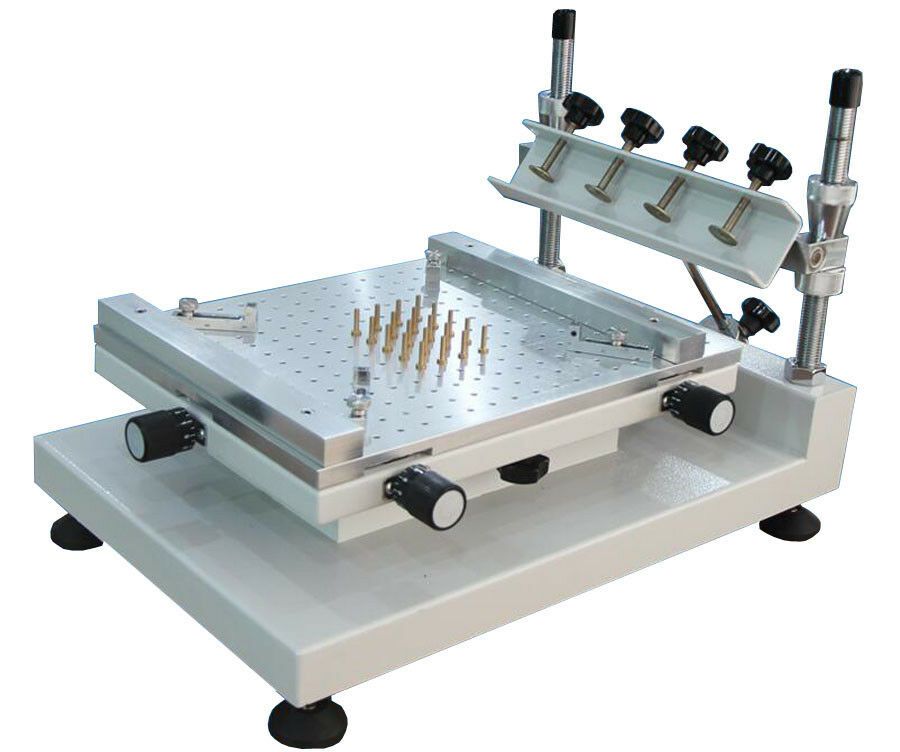 However, what I like about printed stencils is that they are self-aligning. Also, you can customize them easily without thinking much in advance – if you buy the metal one, you have to wait at least a week to get it. With a printed stencil you are ready to go in less than 10 minutes. I see potential here for repairs – you can easily print a partial stencil to, e.g., put paste only for one IC and then to reflow the whole board.
Did you enjoyed the post? Consider supporting me on Kofi:
Share via
3D printing, ElegooMars, ReflowHigh Precision Stencil Printing needs 3D Printing Tools
Ad
evertiq.comevertiq.mxevertiq.esevertiq.fievertiq.seevertiq.plevertiq.de
Ad
© Christian Koenen GmbH PCB | March 05, 2021
According to several studies, roughly half of all soldering defects occurring in SMD assembly production are still closely related with the printing of the soldering paste.
This is a product release announcement by Christian Koenen GmbH. The issuer is solely responsible for its content.
Essential therefore for a high yield is the most suitable choice of high precision stencil printer, adapted printing parameters as well as the optimal precision stencil. Highly precise milled stepped stencils offer a very efficient and economical option for the optimal application of soldering paste. But a stepped stencil is not just a stepped stencil.
The volume of the soldering paste deposit is determined significantly by the material thickness of the printing stencil used.
Image 1:Stepped stencils are used, when the applied quantity of paste can no longer be adequately regulated via the adjustments of the apertures.(© Christian Koenen GmbH)
In other words, if on a circuit board components with a height variance with regard to the component size resp. the soldering paste requirement (unfavorable component mix) are planned, the respective optimal deposit volume can no longer be produced with a conventional stencil (insufficient amount of paste). "Components such as SMD circuit board connection terminals represent particular challenges, because they very frequently feature deviations of the contact surfaces of the component of up to 100 μm to one another resp. to the contact surface." stated Sebastian Bechmann, Application Manager of the Christian Koenen GmbH. They require a stencil thickness of about 150 to 200 μm (defective coplanarity). In contrast the deposits for SMD components of the sizes 0402 can best be printed with 120 to 150 μm thick stencils. One also frequently finds insufficient amounts of paste in the combination μBGA and connector or SMT-components and THR-components.
Patented, milled and laser-cut high precision stepped stencils
Also when Fine-Pitch components are placed close together with standard components (mixed configuration), the conventional stencils come up against their limits and can, for example, cause a bridge-short-circuit formation. Especially with mixed configurations with small grid sizes and a high number of components, a high precision milled and laser-cut stepped stencil from Christian Koenen GmbH, optimally adapted to the layout is often the most efficient and economical option in order to avoid soldering defects right from the start.
 Image 2: Stepped stencils realize the compensation of differences in height in the circuit board surface, so that an artificial jump and the associated print smearing are avoided. (© Christian Koenen GmbH)
Besides the mixed configuration there are other indicators that favor the use of a stepped stencil. Such as when soldering paste is to be applied to different levels. This is required, for example, when individual components are to be sunk in the circuit board or circuit board areas of different thickness, such as rigid and flexible circuit board areas of an assembly are to be printed in one operation (sunken components).
During the course of the technological further development in the area of circuit boards and components, new challenges emerge for the high precision printing. When the circuit board to be printed features particularly sensitive areas such as bonding surfaces, chip mounting (Attach) or point protrusions due to substrate unevenness, excessively high solder resist or protruding via plug, a conventional printing stencil can be damaged in sensitive areas.
 "More and more frequently unwanted uncontrolled jumps within the stencil image develop after multiple use" referred Sebastian Bechmann, Application Manager of Christian Koenen GmbH. More frequent cleaning cycles, printing defects or even damage to the assembly can be the result. Stepped stencils provide a solution here too: These can be provided with cavities at critical areas, which protect the sensitive areas or compensate unevenness in the substrate (unevenness on the circuit board).
In addition the CK stepped stencils enable a combination print: Some SMT shapes must be fixed on the circuit board, so that they cannot lift up or move during the soldering process. With the help of the stepped stencil, here the adhesive can be applied directly after the printing of the soldering paste (print on print).
"Due to the uninterrupted trend towards higher and higher packing density, increased component mix as well as towards the use of smaller and smaller components, an increasing significance of the stepped stencil is to be reckoned with in the assembly production" stated Michael Brianda, CEO of Christian Koenen GmbH.
 The rapidly rising number of assemblies also features several of the challenges described, for which the high precision stepped stencils of the company will be used more and more frequently.
Image 3: Stepped stencil with Plasma Coating: The printing process is improved considerably and thus increases the output of the production line. (© Christian Koenen GmbH)
High precision stepped stencil with Plasma 3 coating
More and more users profit from another innovation from the house of Koenen: The milled, laser-cut stepped stencil with Plasma 3 coating. Thereby, with a plasma-supported chemical vapor deposition a coating is applied reproducibly to the substrate side and in the apertures, which improves the transfer behavior of the soldering paste (defective paste-release behavior). In the meantime the CK-Team has already brought the third generation of the Plasma Coating (Plasma 3.0) onto the market, which is remarkably distinguished in particular in the smallest apertures through very low adhesion forces.
 The smearing of the paste on the circuit board side is reduced and the number of cleaning cycles can be reduced, resulting in savings for production costs as well as throughput time. In addition the coating, which is only a few nanometers in thickness, is chemically and mechanically resistant. This results in fewer stoppages for stencil cleaning.
Electronics production with fully automated printing process
The real challenges in the high precision printing process listed here not only occur individually, rather increasingly also in various combinations:
- insufficient amount of paste
- defective coplanarity of the component contacts
- bridge-short-circuit formation
- sunken components
- unevenness on the circuit board
- print on print
- poor paste-release behavior from the stencil opening
- high number of down times for stencil cleaning
"In support of the Smart Factory and Industry 4. 0 efforts, it is necessary that all production steps can be performed with as minimal an intervention of machine operators as possible" stated Michael Brianda, CEO of Christian Koenen GmbH. The high precision and the customer-specific design of the stepped stencils are absolutely necessary, so that the fully automated stencil printing process can be adapted in the electronics production to smaller and smaller component sizes, new component shapes and increased mixing of large and small components. Last but not least, due to the many years of experience of our personnel and the continuous investments of Christian Koenen GmbH in innovations all about precision printing tools, the error rate in stencil printing could be noticeably reduced. Since the miniaturization and the component mix continue to increase it can be expected, that investments for creative solutions in the design of the printing tool will continue to be necessary. Many of our international customers have confirmed to the company, that the short delivery times of the customer-specific milled and laser-cut high precision stencils with Plasma 3 coating are today innovative and reliable solutions for the increasingly more complex stencil printing applications in SMD and semiconductor production.
 short & concise
Stepped stencils have gained in significance in the production of electronic assemblies and are used, when the applied amount of paste can no longer be adequately regulated via the adjustments of the apertures. The printing process is improved and optimized further through the plasma coating.
Contact
Sales Fais Piroe, Sales Manager
+31 (6) 81 45 90 64
Oliver Ödin, Sales International
+46 (0) 73 066 6490
Editorial Dennis Dahlgren, Editor in Chief, Evertiq.com
+46 (0) 70 394 5550Regional News
Global Evertiq.com Western Europe Germany - Evertiq.de Scandinavia - Evertiq.se Eastern Europe Poland - Evertiq.pl
Evertiq AB
Corporate
Evertiq AB
Vastra Finnbodavagen 2, 6 tr
13130 Nacka
Sweden
January 06 2023 12:34 am V20.10.55-2
© 2023 Evertiq AB
Ad
3D stencils
Filters
Bestsellers
Product price
R - R
- 450 R
- 1500 R
Brand
-
- Kaisi
- Mechanical
- Qianli
Nothing found for these search criteria
nine0021
Our stores
Adler
Astrakhan
Volgograd
Volzhsky
Voronezh
Yekaterinburg
IZHEVSK
9000 9000 9000 9000 KEMEROOVO 9000 000 Kemostoro Korostro Korostro
Moscow
Naberezhnye Chelny
Nizhny Novgorod
Novokuznetsk
Novosibirsk
Omsk
Penza
Perm
Pokhvistevo
Rostov-on-Don
Ryazan
Samara
St. Petersburg
Saratov
Smolensk
9000 9000Ufa
Cheboksary
Chelyabinsk
Cherepovets
Yaroslavl
Free courier delivery is available in the city for purchases over 1,000 rubles. nine0005
There is free courier delivery in the city for purchases over 500 rubles.
The store has a paid delivery by a transport company throughout the Russian Federation.
There is no 'PROFI' store in the city yet, but there is an order pickup point.
BGA Reballing - A-CONTACT
The term reballing (reballing from the English. reballing - “treatment” of the blade of BGA chips) is the replacement of solder balls that are located under the electronic BGA components. nine0005
When working with BGA components, the most frequently asked questions are: "Can the components be reused?" and “How can I reball a component?”. While these questions are certainly relevant to many, today there are very few companies that reball components. Before starting work, you need to deal with the following questions.
Reusability of components
This question must be answered by the supplier of the components, as he knows how many thermal cycles their components are able to withstand. Consider a BGA component mounted on a double-sided SMD PCB that has been removed, reballed, and replaced; potentially he had to go through six soldering cycles during this process in addition to soldering the balls during the production of the component:
- Solder reflow assembly - top side.
- Solder reflow assembly - bottom side.
- Removing a component.
- Removing excess solder from a component.
- Soldering new solder balls.
- Component replacement.
Another important factor is the amount of manipulation and potential ESD damage that can occur during the reballing process. In many cases, the reballing process is not commercially viable due to additional labor costs. In cases where the value of the component is very high or it is difficult to obtain, the need for reballing arises. nine0005
Reballing Methods
There are two main methods most commonly used for BGA reballing: preforms and reballing fixtures. Micro stencils can be used to reapply flux and solder paste to components.
Method 1: Preforms.
One method of reballing is to use solder preforms (usually an array of solder balls suitable for the component, either in a sheet of paper or joined together). Some solder manufacturers offer such blanks. In the case of eutectic balls, such blanks must be soldered to the device in a controlled environment (soldering furnace or head) using a flux. High temperature hard solder balls must be attached to the device with dosed or screen printed solder paste. nine0005
The standard process steps for installing solder balls using BGA preforms are:
To replace the solder balls, it is necessary to prepare contact pads on the part. Solder residue can be removed with a desoldering braid used in conjunction with a direct soldering iron equipped with a blade tip.
Pass the hot blade tip across the pads row by row. The operator must carefully ensure that the braid is between the ferrule and the board. Old solder can be removed quickly without the risk of pad damage that can result from direct contact between the hot tip and the substrate. After this, flux residues on the part must be removed with an approved solvent to keep the installation area clean. nine0005
There are also non-contact desoldering methods that use hot air or nitrogen to melt the solder while a vacuum pipette "sucks" the melted solder from the pad.
This method is available both in automated processes and in manual execution.
Although it has less site contact, it can be more time consuming and require special equipment not always available at repair benches. Therefore, this method can be is more expensive than and is not used as widely.
2. Apply flux . The correct flux must be applied to the pad areas prior to installation, either by dispensing, printing or, more commonly, by brushing.
3. Install preform . Typically, the insertion of a new blank is done by hand, with alignment controlled either by registering the edges or by using a fixture to align the pads with the preforms.
4. Reflow . Once the flux is applied and the preform is in place, the next step is to reflow the part. Solder should be multipoint to match the solder paste flux profile being used. When the solder cycle is complete, the new solder ball array should be successfully attached. At this point, the carrier material must be removed, which can be done in a variety of ways. You can leave the media in deionized water for a few seconds, remove it with tweezers, or remove it with a sprayer or cleaning system. nine0005
The part must be cleaned of flux residues, which can be done by any standard water method.
If paper is removed with a cleaner or sprayer, this step may not be necessary. If a no-clean flux gel is used, the paper can be removed while hot. The paper then does not need to be soaked, which is a big advantage as there is no need for pre-drying. Only full convection from top to bottom works well. If only the top heat is used, then the element will sag and only the balls on the sides of the part will attach, and the central balls will not be soldered. nine0005
It is also important to note that some components are moisture sensitive and therefore require pre-drying prior to any connection to the PCB.
Method 2 Reballing Tools
This method typically involves component-specific stencils and paste or flux application tools to place the solder balls in position prior to soldering - again in a controlled environment.