Horus scanner 3d
Scanning — Horus 0.2rc1 documentation
This workbench is where the 3D scanning process is performed. This process generates a three dimensional point cloud from a physical object. It has three components:
- Settings panel
- Video wall
- 3D scene
Through the menu View these panels can be shown or hidden.
Settings panel
Scan parameters
- Capture texture: enabling this option captures the real color of the object. Otherwise the point cloud has an uniform fake color. If this option is disabled, the process is faster and the color used is the one defined in the Point cloud color section.
- Use laser: selects left laser, right laser or both.
Rotating platform
- Show center: shows the center of the platform using the current calibration values.
- Step: is the angle increased in each scan iteration. The smaller the step, the greater radial resolution, and also more scanning time.
The default value is 0.45º, that is 800 steps per revolution.
- Speed: is the motor speed in degrees per second. Te default value is 200 º/s.
- Acceleration: is the motor acceleration in degress per secon squared. The default value is 200 º/s².
Point cloud ROI
In this section the ROI (Region of interest) is defined. It is a cylindrical volume in the point cloud and a rectangle in the video.
- Use ROI: enabling this option applies the ROI. This region is the one being scanned both in the video and in the point cloud. All information outside won’t be taken into account during the scanning process.
- Diameter: ROI diameter in mm. The default value is 200 mm.
- Height: ROI height in mm. The default value is 200 mm.
Point cloud color
In this section is selected the color for the point cloud when no texture is captured.
Note
The Settings panel is hidden during the scanning process.
Video wall
In this window, two states are distinguished: while not scanning, it shows the video in texture mode. When the scan starts, you can select several views corresponding to the different stages of the image processing.
- Texture
- Laser
- Gray
3D scene
This section is a three-dimensional scene where the scanned point cloud (model) is shown. Also it allows to view meshes in stl format.
To start scanning press the Play button. Also the process can be stopped, paused and resumed. During the scanning, the progress is shown in the bottom of the scene.
You can navigate in the 3D scene using the following shortcuts:
| Action | Shortcut 1 | Shortcut 2 |
| Default views | Home / PgUp / PgDn / End | |
| Rotate | Left click | Shift + Up/Down |
| Rotate horizontally | Up / Down | |
| Rotate vertically | Left / Right | |
| Vertical shift | Ctrl + Mouse wheel | Ctrl + Up / Down |
| Reset vertical shift | Dobule left click | |
| Traslation | Shift + Left click | |
| Zoom | Mouse wheel | Shift + Up /Down |
| Delete object | Right click + Delete object | Del |
| Quit program | Ctrl + Q |
To load, save or reset the 3D model, access from the menu File.
Ciclop - RepRap
Ciclop 3D Scanner Documentation
Main page | Ciclop 3D Scanner Buyer's Guide | Ciclop 3D Scanner Build Manual | Ciclop 3D Scanner User Manual | Ciclop 3D Scanner improvements
Ciclop
Release status: working
| Description | 3D Laser Scanner |
| License | CC-BY-SA |
| Author | User:bq |
| Contributors | CowTech |
| Based-on | None |
| Categories | 3D Scanner |
| CAD Models | |
| External Link | GitHub |
Ciclop 3D Scanner
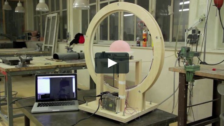
Ciclop is an open source 3D laser scanner with a rotative platform. It has been developed from scratch by BQ, and now it has been released to the community, under Creative Commons Attribution-ShareAlike 4.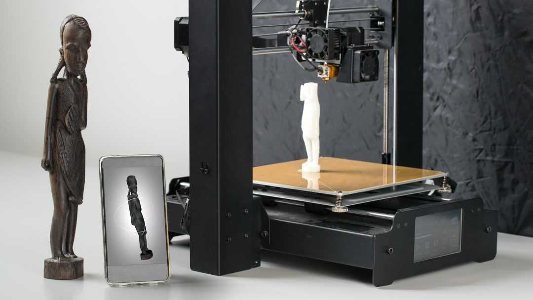 0 International License.
This 3D Scanner is composed by a structure of 3D printed parts, threaded rod, a Logitech C270 web cam, two line lasers and a turntable platform with a stepper motor.
Related to this device, Horus, a complete desktop application for 3D scanning, has been developed also from scratch.
In early 2015, CowTech Engineering released their version of the Ciclop, raising over $183,000 USD on Kickstarter. They made some changes to the physical design, but still use Horus as the scanning software. The CowTech version uses adjustable laser holders and connects the scanner using laser cut acrylic instead of threaded rod. They also redesigned the printed parts and reduced the 3D printer build volume needed to make the parts at home.
Specifications
| CowTech Ciclop | BQ Ciclop (via Lulzbot) | |
|---|---|---|
| Scan Time | 2-8 min | 2-8 min |
| Resolution | 0. 5mm 5mm | 0.5mm |
| Cost (USD) w/o Printed Parts | $119 | na |
| Cost (USD) w Printed Parts | $159 | $400 |
| Scan Area (mm) | 200 x 200 x 205 (h) | 200 x 200 x 205 (h) |
| Adjustable Laser Position | Yes | No |
| Frame Material | Laser Cut Acrylic | Steel Threaded Rod |
Both the Ciclop and Horus are works in progress, and the developers at BQ and CowTech would appreciate it if users shared any modifications with the open source community to continue development of these projects.
Contact on the Google Group or send an email to [email protected]
Resources
Most the important resources for assembling, calibrating and using the scanner, CAD models and .stl files, as well as Google and FB communities from BQ and CowTech are compiled in one place at the CowTech Resources tab. For more detailed resources, particularly pertaining to the development of Horus, please explore the GitHub and DIWO links below.
GitHub
- Sources
- Wiki
- Background / Scientific documentation
DIWO
- Presentation
- 3D Design
- Electronics
- Firmware
- Software
Where to buy?
- he3d
- CowTech Ciclop 3D Scanner
- HE3D Ciclop DIY 3D Scanner Kit Free Worldwide Shipping 130 USD |3D Printers Bay
3D scanner for production facilities
Toggle Nav
Back
June 29, 2021
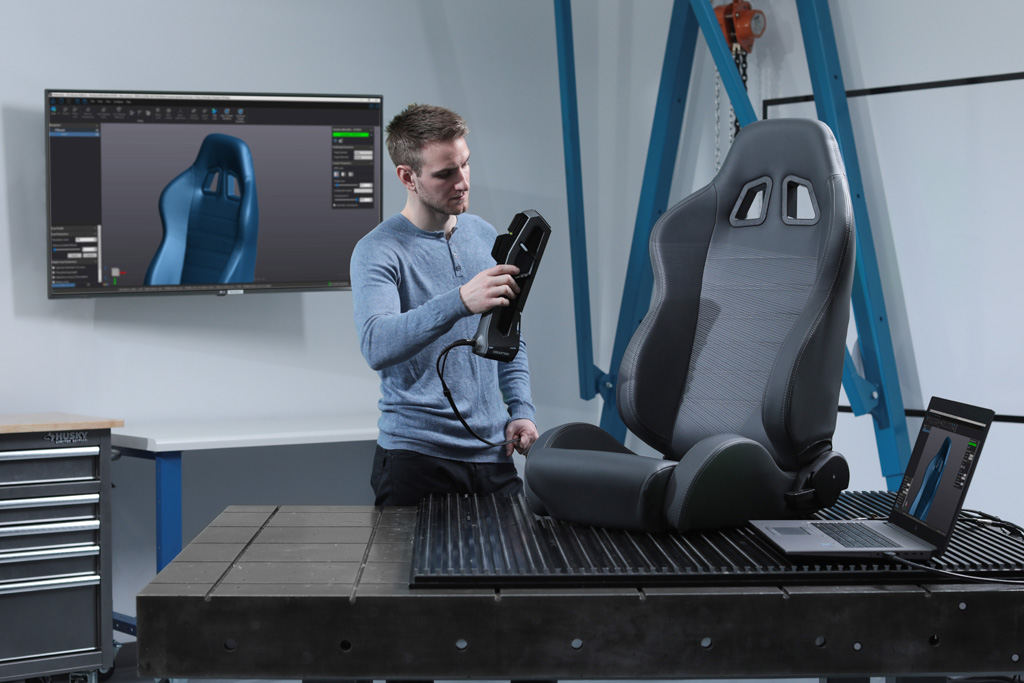
Industrial 3D scanners digitize and create mathematical models of objects. This equipment is portable and can be moved and scan large objects from multiple sites. Devices calculate the distance to the surface of the object, fix the coordinates of points and build accurate 3D models.
Industrial 3D scanners differ in scanning range and accuracy - there are modifications for small details, options for large parts and objects, for creating a digital version of the landscape and structures. Scanning accuracy - from 0.01 mm in a stationary version and up to 2 mm at a distance of 25 meters for portable 3D scanners. The resulting digital model can be processed in any design and engineering programs: edit, measure, control geometry, compare with a CAD model, evaluate the state of elements, etc.
Applications of industrial 3D scanners in the manufacturing sector:
- Layout of workshops, warehouses, communications. The scanner can create a digital model of a room or an object outside, correct, change the design. It is used during reconstruction, installation of new equipment, laying of communications.
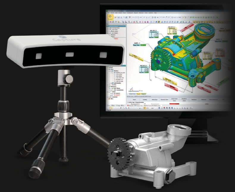
- Product quality control. To perform a specific operation, a scanner of the required accuracy is selected, which can then be used automatically: check dimensions, dimensions, holes, rounding, alignment and other parameters.
- Industrial design. The digital model of any object can be edited, a new design can be created.
- Reverse simulation. Scanning and digitization of large objects, industrial equipment, metal structures. Digital models can be modified in specialized programs, measurements can be taken, and changes can be made to the design.
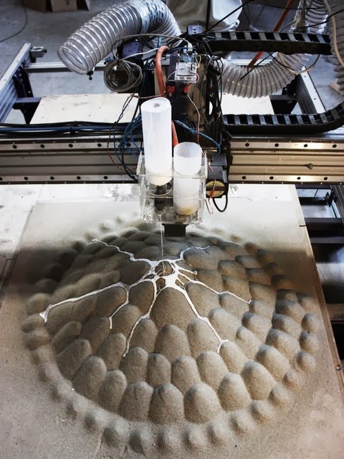
- Creation of tooling for making casting molds. The scanner provides accurate scanning of the product, then the result is corrected and tooling for the manufacture of sand molds is produced on a CNC machine.
One of the universal solutions for 3D scanning is FARO FOCUS S70.
This is an accurate and easy-to-use device that automatically scans the area at a distance of up to 70 m. At a distance of up to 10 m, the scanner creates digital models of objects with an accuracy of 1 mm, at a distance of 25 m - up to 2 mm.
 The basic FARO SCENE software allows you to perform the primary processing of 3D scanning data - visualizes information, combines scans, and takes measurements. After SCENE, you can use the As-Built object modeling software platform in Autodesk or other object processing software.
Scanning the shops of the Kola Mining and Metallurgical Combine.
As part of a large-scale project for the reconstruction and construction of the Kola Metallurgical Plant, the next stage of scanning the territory of the workshops under construction was completed.
A total of 598 scans were received. Based on the scanned materials, a three-dimensional model was built.
FARO FOCUS S70 3D scanning device can be purchased from our company. If you have any questions about the configuration or technical specifications, please consult our technical specialists by calling +7 (495) 988-20-00 or email [email protected]
© 2015–2021 Norgau Russland LLC
3D Terrestrial Laser Scan
Point cloud examples
Despite the fact that the first terrestrial 3D scanners appeared in the last century, there is no reason to state that 3D laser scanning technology is widely used in geodesy. The main reasons, probably, are the still high cost of such systems and the lack of information on how to use them effectively in various applications. Nevertheless, interest in this technology and its demand in the market of geodetic equipment are growing exponentially every year.
What is a 3D laser scanner?
According to the type of information received, the device is in many ways similar to a total station. Similar to the latter, the 3D scanner uses a laser range finder to calculate the distance to an object and measure vertical and horizontal angles to obtain XYZ coordinates. The difference from a total station is that daily shooting with a ground-based 3D laser scanner is tens of millions of measurements. Obtaining a similar amount of information from a total station will take more than one hundred years ...
The initial result of a 3D laser scanner is a point cloud. In the process of shooting, three coordinates (XYZ) and a numerical indicator of the intensity of the reflected signal are recorded for each of them. It is determined by the properties of the surface on which the laser beam falls. The point cloud is colored depending on the degree of intensity and after scanning looks like a three-dimensional digital photo. Most modern models of laser scanners have a built-in video or photo camera, so that the point cloud can also be painted in real colors.
In general, the operation of the device is as follows. The laser scanner is mounted opposite the object to be filmed on a tripod. The user sets the required point cloud density (resolution) and survey area, then starts the scanning process. To obtain complete data about an object, as a rule, it is necessary to perform these operations from several stations (positions).
Then the initial data received from the scanner is processed and the measurement results are prepared in the form in which they are required by the customer. This stage is no less important than field work, and is often more time-consuming and complicated. Profiles and sections, flat drawings, three-dimensional models, calculations of areas and volumes of surfaces - all this, as well as other necessary information, can be obtained as the final result of working with a scanner.
Where can laser scanning be used?
Main applications of 3D scanning:
- industrial enterprises
- building and architecture
- road shooting
- mining
- monitoring of buildings and structures
- documentation of emergencies
This list is far from complete, since every year users of laser scanners perform more and more unique projects that expand the scope of technology.
Laser Scanning from Leica Geosystems - History of Laser Scanners
The history of Leica laser scanners began in the 90s of the last century. The first model 2400, then under the Cyra brand, was released in 1998. In 2001, Cyra entered Leica Geosystems into the HDS (High-Definition Surveying) division. Now, after 14 years, Leica Geosystems introduces a line of two scanning systems on the market.
As mentioned above, 3D laser scanning is used in completely different areas, and there is no universal scanner that would effectively solve all problems.
For shooting industrial facilities where a long range is not required, but the model must be very detailed (that is, an accurate high-speed device is needed), the laser scanner Leica ScanStation P30 will be optimal: range up to 120 m, speed up to 1,000,000 points per second.
Completely different requirements are imposed on the scanner when it comes to shooting opencast mines and storages of bulk materials in order to calculate volumes. Here, centimeter accuracy of the rangefinder is enough, and the shooting range and protection from weather conditions and dust come to the fore. The ideal tool for scanning in such conditions - Leica HDS8810 with a range of up to 2,000 m and IP65 dust and water resistance. In addition, this device is the only one on the market of scanning systems that operates in the temperature range from -40 to +50 degrees. That is, the HDS8810 is a laser scanner that works in all weather conditions.
The key model of Leica Geosystems' HDS division is the Leica ScanStation P40 . The famous and most popular ScanStation line in the world, whose history began in 2006, was replenished in April 2015 with the P40 scanner. The P40 inherited the accuracy and speed from the previous model, but has become more long-range, and the data quality has become even better. In terms of the range of tasks to be solved, this device is truly a leader in its segment. It is no coincidence that despite the "youth" of this model, it has already gained wide popularity in the world.
Laser Scan Data Processing Software (Point Clouds)
It is impossible not to say a few words about the software for processing data received from the scanner. Potential customers pay undeservedly little attention to this component of the 3D laser scanning system, although data processing and obtaining the final result of the work are no less important stages of the project than field work. The range of Leica HDS software is truly the widest on the laser scanning market.
The main element of the spectrum is, of course, the Cyclone complex.