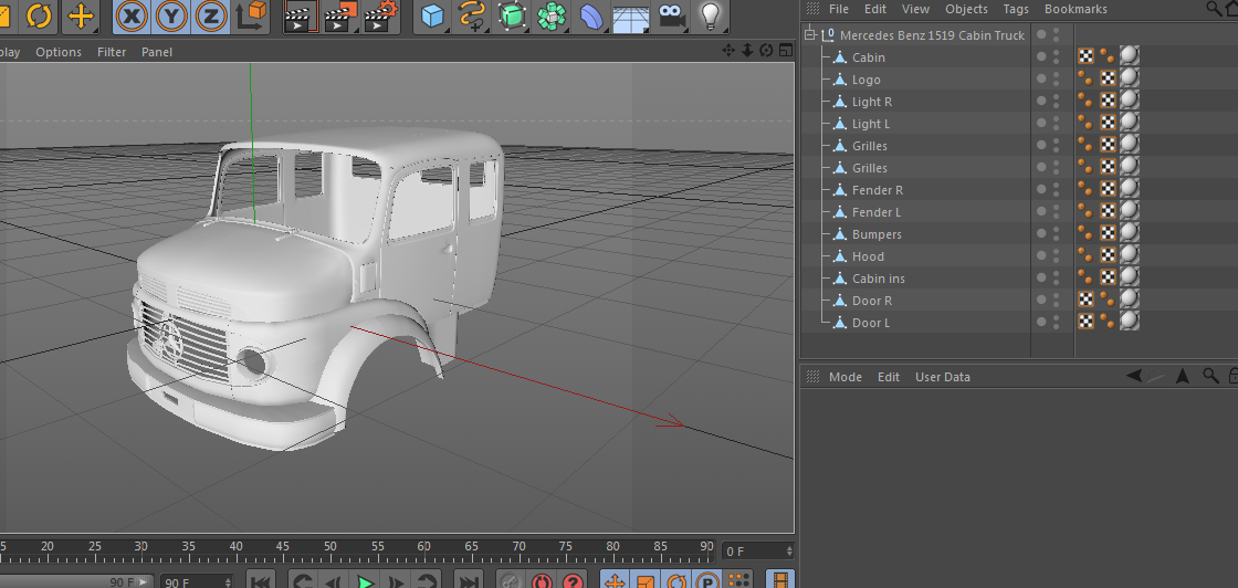
3D rapid prototype printer
What is Rapid Prototyping with 3D Printing?
What is Rapid Prototyping with 3D Printing?USA & Canada
Select your country and region
- Americas
- English
- Español (México)
- Português (Brasil)
- EMEA
- English (United Kingdom)
- Deutsch
- Español
- Français
- italiano
- APAC
- 中文(简体)
- 日本語 (日本)
- 한국어(대한민국)
- English (India)
USA & Canada
What is Rapid Prototyping?
Rapid prototyping with 3D printing is the quick, easy, cost effective way to turn great ideas into successful products. Do you need concept modeling to put your newest ideas to the test? What about functional prototyping to gauge performance before committing to costly production tooling? Rapid prototyping solutions from Stratasys will give you the flexibility to create, test and refine in ways you never thought possible so you can go to market faster than ever before.
See how 3D printed rapid prototypes are changing the way the world does business
"Every time we avoid cutting a tool, we save 8 to 12 weeks."
Randy Larson, Polaris Industries
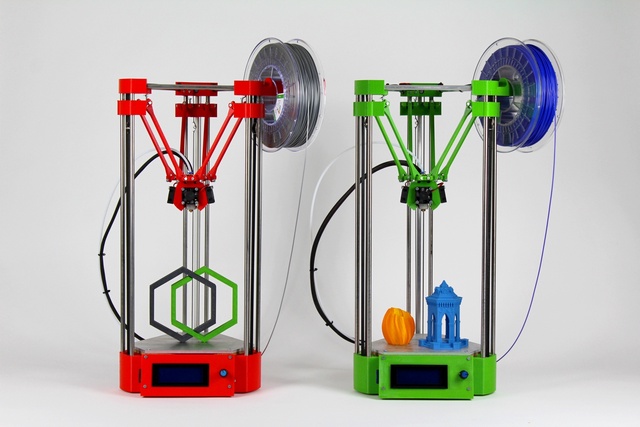
3D Printers for Rapid Prototyping
Go from idea to manufacturing ready prototype in a matter of hours
with Stratasys 3D printers
Get A Quote
Prototype Faster and more Effectively with Reliable 3D Printing Technology
Stratasys 3D Printers dramatically tighten design and development cycles, improve communication and collaboration, and resolve issues between design and engineering. They speed products to market and reduce costly mistakes — all while keeping your intellectual property onsite. Very soon, you’ll wonder,
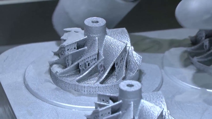
- Metal Prototyping 3D Printers
Metal Prototyping 3D Printers
Prototype Faster and more Effectively with Reliable 3D Printing Technology
Desktop Metal® Shop System™
A metal binder-jetting 3D printer designed for machine shopsAs the first binder jetting system designed for machine shops, Shop SystemTM lets your shop take advantage of affordable, high-quality binder jetting technology. It prints end-use metal parts with unrivaled speed, print quality and productivity. A complete, end-to-end solution, the Shop SystemTM includes a printer, powder station and furnace, and easily integrates with your existing shop operations.
View Item
X Series – InnoventX
Compact binder jet 3D printer for the production of metal, ceramic, or composite parts
The Desktop Metal InnoventX is engineered to 3D print high-density near-net-shape parts in a wide range of standard MIM powders, metal alloys, ceramics, or technical composites. Powered by Triple ACT Powder Compaction and a piezoelectric print head system, the InnoventX produces parts with tight tolerances, excellent surface quality, and the part density needed for functional applications. Discover how binder jetting can enhance education, research, prototyping, rapid product development, and the short-run production of small components.
View Item
FIGUR G15 | Desktop Metal
Low-mid volume metal sheet forming on-demandFigur G15 is the first commercial platform to directly shape standard sheet metal on demand from a digital design file using all-new, patent-pending Digital Sheet Forming (DSF) technology. This translates into no stamping tools, molds, dies, or presses that traditional sheet metal fabrication requires.
View Item
Desktop Metal® Fiber™
High-Resolution Parts with Industrial-Grade Composites from a Fast, Affordable Desktop 3D PrinterFiberTM is the world’s first desktop 3D printer that lets users build high-resolution parts with the industrial-grade continuous fiber composite materials used in automated fiber placement (AFP) processes. Users can print parts of exceptional strength and stiffness (twice the strength of steel at 20% of the weight), in a broad range of materials that previously required million-dollar AFP systems. All from their desktop.
View Item
Give us a call and speak to an expert.
Contact Us
Sign Up to Receive Our Latest News & Hottest Promotions
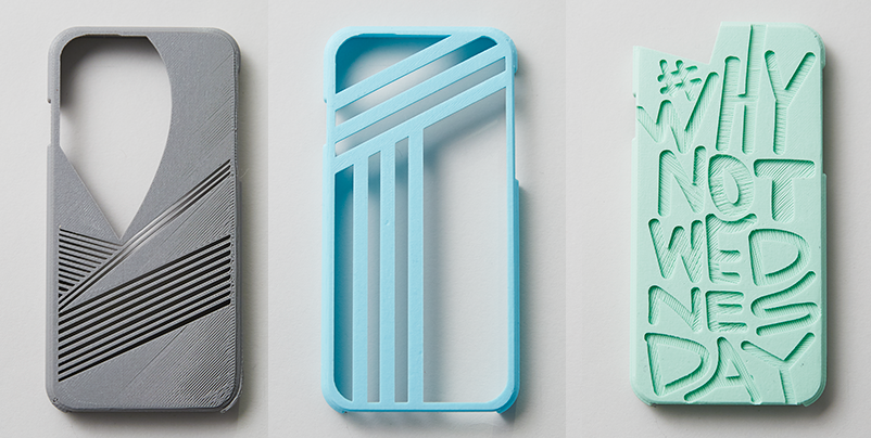
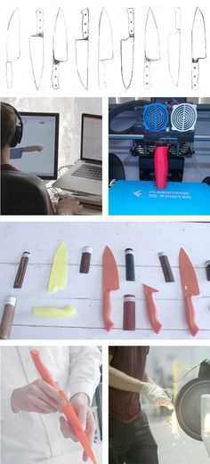
3D Printing Applications: Rapid Prototyping
Rapid prototyping enables companies to turn ideas into working proofs of concept, transform concepts into high-quality prototypes that look and work like finished products, and test products for mass production.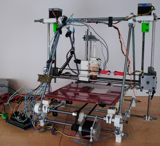
No more waiting weeks for prototypes to arrive. With your own 3D printing, you can create rapid prototypes in one day, test, redesign, and print again. nine0003
STEP 1
Design
Design the object in CAD during business hours.
STEP 2
3D Print
Create 3D prototypes overnight.
STEP 3
Test
Clean, measure, test, build and collect feedback on your design in the morning.
STEP 4
Repeat
Adjust design and repeat process.
Although the cost of setting up a printer may seem high, it pays for itself in just a couple of weeks or months. Believe me, you will spend much more on outsourcing or an alternative production method. nine0003
Calculate time and cost
Prototyping speaker cabinet
16.5 x 13.5 x 13.5 cm
6.5 x 5.3 x 5.3 inches
Ecosystem of affordable 3D printers and Formlabs high-performance materials can be used to create highly detailed prototypes.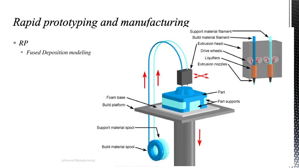 With Draft Resin you can print models up to four times faster than standard Formlabs resins, making Draft Resin ideal for initial prototyping and print iterations to bring products to market faster. nine0003
The
Form 3 High Performance Stereolithographic 3D Printer creates molds with very high surface quality and detail, allowing you to meet all design requirements in manufacturing, and virtually eliminating the need for post-processing. Build industrial-quality prototypes at an affordable price so your team can print new models in just a few hours.
Use the Form 3 at various stages of production for faster return on investment. The Formlabs ecosystem seamlessly integrates into any product development process, from 3D printing prototype models to manufacturing molds for small-scale production. nine0003
Buy Form 3Request a Sample
Find additional resources to help you get started with Formlabs 3D printers and experience rapid prototyping.
3D printing and other rapid prototyping systems / Sudo Null IT News
A little over a week ago, an article on this topic appeared on Habré, but it poorly covered the technical side of printing and caused a fairly large number of questions. What I will try to fix in this post. nine0003
Three-dimensional printing is one of the methods of rapid prototyping. There are now dozens of rapid prototyping methods. All of them differ from each other, but they consist in the layer-by-layer imposition of a composite material and can significantly reduce the time for manufacturing models for visualization, fitting, tooling and other applications, which provides:
- reduction of the development cycle;
- design improvement;
- quality improvement;
- reduction in product price and production;
- speed up design changes.
The main advantage is the ability to create a product in the presence of only a geometric model.
In this case, the product is created in one go, and there is no need to plan the sequence of technological processes. However, compared to CNC machines, the choice of material for the product is very limited.
The technology of forming products by gradually building up material appeared around the beginning of the 1980s. The process is based on 3 stages: the formation of a cross section, the layer-by-layer imposition of sections and the combination of layers. That is, to create a product, you only need to know the cross section. This solves some of the product creation problems:
- There is no need for topological design and conversion of structural elements into fabrication elements. Cross sections are generated from the model only. nine0098
- One-step production of a part minimizes the amount of equipment.
- No need to define empty space geometry, as material is being added, not removed.
- It is not necessary to design the design of fasteners and clamps.
- The process is toolless, so there is no need to develop additional tooling.
There are several ways to create and combine cross section layers:
3D printing
It was developed at the Massachusetts Institute of Technology and got its name because of its similarity to printing with a conventional printer. The process is as follows:
- A layer of ceramic powder is applied to the platform
- The print head applies a special binder, due to which the particles adhere to each other and the required cross section is formed
- The platform is lowered one layer thickness and material is applied onto it. nine0098
- Applying the adhesive to the new layer and bonding it to the first layer.
- Execution required number of repetitions.
- Additional heat treatment during which the part hardens completely.
Solid Ground Curing (SGC)
Each layer is cured by exposure to a UV lamp. In this case, all points of the layer harden simultaneously, and final curing is not required. The process consists of the following steps:
- Based on the given geometric model and the desired layer thickness, a set of cross sections is calculated;
- For each layer, an optical mask is made according to the shape of the cross section;
- Platform coated with liquid photopolymer;
- A mask corresponding to the cross section is placed over the polymer layer and the plastic is exposed to an ultraviolet lamp;
- Removal of residual liquid;
- Filling voids with liquid wax.
 After it hardens, the layer is ground down to the required thickness with a grinding disc; nine0098
 - The product is covered with a layer of liquid polymer and the process is repeated until the finished product is obtained;
- Cured wax is melted and removed from the product.
The advantage of the method is that there is no need for additional supports, since all voids are filled with wax. Also, due to uniform irradiation with ultraviolet, a greater uniformity of the product is achieved and additional curing is not required.
Laser Stereolithography
- Coined by K. Hull, who founded 3D Systems Corporation in 1986 to manufacture this equipment. Manufacturing process includes:
- The photopolymerizable composition is poured into a bath and a platform capable of moving in the vertical direction at a depth equal to the layer thickness is placed in the same bath.
- An ultraviolet laser scans the polymer layer, curing the polymer into a cross-sectional shape.
 nine0098
 - The platform is lowered to the thickness of one layer and a new surface scan is performed. This is repeated until the finished part is received.
- Post curing for final curing. This is necessary because. That liquid areas may remain in each layer. Since the size of the laser beam is finite, the process can be compared to painting over a figure with a ballpoint pen.
The method is one of the most popular, but if the part has a cutout at the bottom, the creation of supporting structures is required. As a result, the surface roughness of the finished product without any processing does not exceed 100 microns. Cured FPC is easy to polish. The strength of the finished parts is comparable to the strength of products made from cured epoxy resins. Finished models can withstand heating up to 100°C without changes in shape and size. nine0003
where 1 is the laser; 2 - product; 3 - liquid monomer; 4 - bath; 5 - mobile platform; 6 - mirror controlling scanning; 7 - leveling knife.
Selective Laser Sintering (SLS)
The process was developed by the American company DTM and is as follows:
- Powdered material is applied to the platform with a special leveling roller;
- The layer of powder is selectively scanned and heated by a laser beam. As a result, the particles stick together and form the required cross section of the product; nine0098
- The platform is lowered one layer thick and the powdered material is applied to it;
- The laser scans again, causing the particles and layers to stick together;
- Steps three and four are repeated until the desired item is obtained;
- Some materials require additional sintering.
Additional supporting structures are not required, due to the filling of voids with powder. The advantage of the method is the possibility of using any fusible powder, including metal. The method is mainly used for the manufacture of molds with a resource of 2,500 to 10,000 pieces. nine0003
where 1 is a laser, 2 is an optical system, 3 is a finished product, 4 is a movable (along the Z axis) working platform, 5 is a hopper for supplying powder material, 6 is a powder material, 7 is a movable hopper table, 8 is a feed roller powder and leveling layer
Lamination (LOM - Laminated Object Modeling)
The part is obtained by laminating and laser cutting the incoming sheet material. Sticking occurs due to the thermal adhesive coating.
- Each sheet is bonded to the workpiece using heat and pressure. The sheet material is fed as a continuous roll from one side and received from the other side. The required temperature and pressure are provided by the rolling roller. Moreover, when gluing a new layer of film, the support platform is shifted down by the value of the film thickness;
- After the sheet is attached, it is scanned along the contour of the cross section. Typically 25 or 50 watt carbon dioxide lasers are used.
 Due to the fact that scanning goes only along the contour, we get much better performance than when using methods with raster scanning; nine0098
 - Areas outside the contours are cut into small pieces for subsequent removal;
- After applying the last layer, the excess material is broken and the finished part is removed;
- The surface of the part is then ground, polished or painted. The finished part can be coated with sealant to protect it from moisture.
The presence of additional material has both pluses and minuses. On the one hand, this allows you not to make special props. Due to this, the part is not deformed during the manufacturing process. However, removing this material is not an easy task. Furthermore, it is not possible to fabricate a hollow structure with closed surfaces. Also, the disadvantage of this method is a large amount of waste remaining in the roll and removed during the cleaning process. nine0003
Due to the bonding of the layers of material, different physical and mechanical properties are observed depending on the height of the product.