3D printer g29
troubleshooting - G29 UBL G-code - every request levels bed?
$\begingroup$
- Every time I issue a
G29command the printer runs through all its multi-point/probing bed leveling routine.
Is this normal? or can I issue one G29 command with suffice to rule them all! :-)
- When I issue
G29 S1to save the topology to the printer makes a buzzing noise with output :
READ: echo:busy: processing busy: processing READ: echo:busy: processing busy: processing READ: echo:busy: processing busy: processing
Below is my Start G-code for reference to this issue.
; reset BL Touch twice M280 P0 S160 M280 P0 S160 ; set Acceleration settings ; M204 ; set JERK X/Y to 8s ; M205 X10 ; set E-Steps for 3DPW Grey PLA E-Steps test results M92 E106.6 ; save those settings M500 ; home all axes G28 ; set temporary nozzle temp to prevent oozing during homing and auto bed leveling M104 S120 ; perform auto leveling G29 P1 ; extrapolate leveling G29 P3 ; set fade height to 10mm ***NOT sure this is needed with an almost flat bed out by 0.2mm ?! ; G29 F10 ; Saves the bed topology results into slot one. ; G29 S1 ; ***NOT*** a god idea - makes a bad bussing noise and never completes ; save for future use M500 ; Loads mesh #1 for the current print job IF previously saved ! ; G29 L1 ; set target extruder nozzle temperature and wait (if heating) M109 S[extruder0_temperature] T0 ; wait for extruder temp ; use absolute positioning for the XYZ axes G90 ; move to the Y=20mm position on the bed = FRONT G1 Y20 F3600 ; move to the X=200 mm position on the bed = MIDDLE G1 X200 F3600 ; purge nozzle G1 E25 F300 ```
- troubleshooting
- g-code
- bed-leveling
- bltouch
- fdm
$\endgroup$
1
$\begingroup$
The Th4D article "Storing Bed Leveling Mesh & Updating Your Slicer" I think can help.
A summary of that write-up:
- Send a
G28 - Preheat the machine to your normal print temperature.
 Let the printer sit at temperature for 5 minutes to let everything expand as it heats
 - Send a
G28 - Send a
G29 - Send
M500
After doing these steps the mesh is now stored in the printer EEPROM.
Then: Update your slicer to use the stored mesh
- Load your slicer and open up the settings where the starting G-code is stored
- Replace the
G29withM420 S1(2.5 If you want to use ABL fading useM420 S1 Z10– This will fade ABL compensation until it is off over the first 10 mm of the print.) - Slice up some files!
My Cura start G-code.
M75 ; Start Print Timer and Engage Fil Sensor if USB Printing M84 E ; Disable E Motor for probe accuracy on direct drive systems M117 Antiblob retract... G92 E0 ; Reset Extruder distance to 0 G1 E-2 ; Retracts filament to prevent blobs during probing G92 E0 ; Reset Extruder distance to 0 M117 Homing All... G28 ; home all axes M117 Heaters Recovering... G4 S10; wait for heaters to recover M420 S1 Z2; Retrieve saved mesh, Z fade 2mm M900 K0; LA M117 Purging extruder... G92 E0 ; reset extruder G1 Z2.0 F3000 ; move z up little to prevent scratching of surface G1 X0.1 Y20 Z0.3 F5000.0 ; move to start-line position G1 X0.1 Y100.0 Z0.3 F500.0 E15 ; draw 1st line G1 X0.4 Y100.0 Z0.3 F5000.0 ; move to side a little G1 X0.4 Y20 Z0.3 F500.0 E30 ; draw 2nd line G92 E0 ; reset extruder G1 Z1.0 F3000 ; move z up little to prevent scratching of surface M117 Printing.....
Hope it's of help.
$\endgroup$
marlin - G29 Auto Grid Leveling Doesn't Do Anything
I have an Ender 3 Pro, recently added a BLTouch v3, flashed a bootloader, and I'm now attempting to configure Th4D U1.R2.15 firmware.
I have only modified configuration.h, haven't touched any other file, and configured it using the inline comments as a guide.
Everything seems to work ok, apart from it doesn't do a grid/mesh level before the print. G29 has been added just after G28 in Cura in the Start gcode box.
When I print something, this happens:
- Bed + hotend heats up.
- X/Y get homed.
- Nozzle moves to the center.
- BLTouch slowly comes down to probe the bed twice to set the level based on that one single center point.
- Primes the filament and begins the print...
I'm not sure what the correct sequence is but I would have thought it should probe 9 points in a grid as I have set #define EZABL_POINTS 3.
Have I missed something in the config?
configuration.h (have omitted all other printer sections to allow stackexchange to accept the rest of the file)
/** * ************** How to use this firmware - READ THIS, yes actually read this. ********************************* * * Uncomment means removing the 2 // in front of #define. * * FLASHING NOTES: * ALL slicers (Simplify3D, Cura, Slic3r, etc) or anything else that connects to the COM port must be CLOSED for the firmware to be flash.* If anything is connected to the COM port when flashing it will fail, typically "access denied" is listed in the error section of the Arduino IDE. * You MUST use the Included Arduino IDE to flash the firmware if on Windows and if you are on a Mac or Linux follow the guide in our knowledgebase to setup your IDE to work with the firmware. * * EZABL SETUP NOTES: * If you have EZABL uncomment the mount you are using with the printer. * If you have a custom/unsupported mount uncomment #define CUSTOM_MOUNT and enter your offsets * below in the CUSTOM MOUNT section. Refer to the EZABL guide to get your offsets. * * STEP 1: * Select the correct board from the tools menu for the printer you are flashing. * Read the printer title for the model you are flashing, it will show what board to select. * * STEP 2: * Uncomment the printer you want to flash. The printers are sorted A-Z by brand name. * If you are using the Creality Dual board with the Ender 3/Ender 5/CR-20 then read the specific section below in that printer section on how to do this.
* * STEP 3: * Select the COM port your printer is on from the Tools menu. If you do not see the COM port try * downloading the latest drivers from the manufacturer or Th4D site on our knowledgebase. * * STEP 4: * Verify you have the correct board selected, printer model uncommented, and if you are using EZOUT and/or EZABL * the lines you need to use them are also uncommented. * * STEP 5: * Once you have your settings verified click the arrow in the upper left to upload to the board. * * STEP 6: * Reset your eeprom. You can send M502 then M500 to reset the EEPROM OR on the printer LCD go to * Control > Reset EEPROM to clear out the EEPROM to defaults. * * BOOTLOADER FLASHING NOTES: * For flashing your bootloader with an Uno make sure to select Arduino as ISP for the programmer * * There are other features in the Th4D Extras section so look there for V6 Hotend, * Bootscreen settings, Titan Extruder and more. You only need to edit this file. * * ERROR NOTES: * If you get errors flashing READ the message it gives you and double check that you selected * the correct board from the Tools menu in Arduino.
Turn off any AV systems and reboot the computer. * * COMMUNITY REQUESTED FEATURES NOTE: * All features in the community requested features section are provided as-is with no support from Th4D. */ #ifndef CONFIGURATION_H #define CONFIGURATION_H #define CONFIGURATION_H_VERSION 010109 //=========================================================================== //============================ Th4D Configuration =========================== //=========================================================================== // ONLY UNCOMMENT THINGS IN ONE PRINTER SECTION!!! IF YOU HAVE MULTIPLE MACHINES FLASH THEM ONE AT A TIME. //=========================================================================== // Creality Ender 3 Options - Select 'Sanguino 1284p' from Tools > Board //=========================================================================== #define ENDER3 // If you are using our EZOut V1/V2 (connected to LCD header) filament sensor kit please follow the install guide // and then uncomment the #define EZOUT_ENABLE line below.
// Do NOT ever connect our filament sensor without the supplied adapter board. //#define EZOUT_ENABLE // EZABL Probe Mounts (Ender 3 uses the same mounts as CR-10) //#define CR10_OEM //#define CR10_VOLCANO //#define CR10_V6HEAVYDUTY //#define TM3DAERO //#define TM3DAERO_EXTENDED //#define PETSFANG //This is the RIGHT mounted version - if using the left mount please use the CUSTOM_PROBE option. #define CUSTOM_PROBE // TMC2208 Creality Board Setting - uncomment this to set the driver type if you are using the TMC Creality board //#define TMC_CREALITY_BOARD //================================================================================================= // README - THE BELOW SETTINGS ARE ONLY FOR USING THE CR-10S DUAL BOARD WITH THE ENDER 3 // DO NOT UNCOMMENT THE ABOVE #define ENDER3 LINE IF USING THE DUAL BOARD // Select 'Arduino Mega 2560' from Tools > Board - NOT Sanguino // // To use the Ender 3 LCD with the CR-10S dual board board connect the LCD cable to EXP1 on the // CR-10S board but rotate it 180 degrees.
The LCD end of the cable goes to EXP3 on the Ender 3 LCD. // You will have to force it into the EXP1 but it will fit and work. // // EZABL and EZOut support are still supported just use the lines above this comment section. //================================================================================================= //#define ENDER3_DUALBOARD // Dual Extruder Board Options - The below options are for use with the Th4D CR-10S Board with dual extruder support. // If you are using a single hotend with the 2 into 1 adapter OR mixing nozzle uncomment the below line //#define DUAL_EXTRUDER_SINGLE_HOTEND // If you are using a dual hotend with dual nozzles uncomment the below line //#define DUAL_HOTEND_DUAL_NOZZLES // If you are using a 2nd EZOut V2 (connects to Y+ connector) filament sensor kit please follow the install guide // and then uncomment the #define EZOUTV2_DUAL_ENABLE line below. Do NOT ever connect our filament sensor without the supplied adapter board. //#define EZOUTV2_DUAL_ENABLE // Use Ender Bootscreeen instead of Th4D //#define ENDER_BOOT //=========================================================================== // ************************* END PRINTER SECTION ************************* //=========================================================================== //=========================================================================== // EZABL Advanced Settings //=========================================================================== // If you want more or less EZABL probe points change the number below (only used if EZABL enabled) // Default is 3 which gives you 3x3 grid for a total of 9 points.
STICK WITH ODD NUMBERS #define EZABL_POINTS 3 // If you want to probe in on the bed more than 15mm change this below. // Do not use 30mm for the Standard CR-10/s or the S4 as you will be on the bed screws. // Try 50mm to avoid the binder clips if you use them. Do NOT go under 15mm here. // You can do down to 10mm on the Wanhao i3 since it cannot print on the entire bed. // You can do down to 5mm on the Wanhao i3 Mini since it cannot print on the entire bed. // (only used if EZABL enabled) #define EZABL_PROBE_EDGE 15 // If you have issues with your machine running the faster probe setting disable the #define EZABL_FASTPROBE below. // DO NOTE: Most machines will work with the fast probe enabled. Use M48 to verify accuracy. #define EZABL_FASTPROBE // This will disable the XYE motors during probing. Can be useful if you have stepper motors causing interference issues with the EZABL sensor. //#define PROBING_MOTORS_OFF // Heaters will stay on during probing - only use if directed to by support.
Do not use on AC beds. #define HEATERS_ON_DURING_PROBING // Letting the bed heat recover between probes can increase accuracy due to the bed warping during cooling/heating // Enabling the below option will let the bed get back to temperature during probing but will increase probing times. //#define WAIT_FOR_BED_HEATER // If you want a more granular control over the babystepping uncomment the below line. // This will make the adjustment finer than the standard setting. //#define FINE_BABYSTEPPING // This will extrapolate the implied tilt of the bed outside of the probe area. Do not comment out unless directed by support. #define EZABL_OUTSIDE_GRID_COMPENSATION // Does your machine make weird noises/vibrations when it is probing the mesh? Enable this to slow down the speed between probe points. //#define SLOWER_PROBE_MOVES //================================================================================ // IF YOU HAVE A CUSTOM PROBE MOUNT OR ONE THAT IS NOT PRE-SUPPORTED UNCOMMENT THE // CUSTOM_PROBE OPTION IN YOUR PRINTER SECTION AND ENTER YOUR PROBE LOCATION BELOW //================================================================================ #if ENABLED(CUSTOM_PROBE) /** * Z Probe to nozzle (X,Y) offset, relative to (0, 0).
* X and Y offsets must be whole numbers. * * In the following example the X and Y offsets are both positive: * #define X_PROBE_OFFSET_FROM_EXTRUDER 10 * #define Y_PROBE_OFFSET_FROM_EXTRUDER 10 * * +-- BACK ---+ * | | * L | (+) P | R <-- probe (10,10) * E | | I * F | (-) N (+) | G <-- nozzle (0,0) * T | | H * | (-) | T * | | * O-- FRONT --+ * (0,0) */ #define X_PROBE_OFFSET_FROM_EXTRUDER -44 // X offset: -left +right [of the nozzle] #define Y_PROBE_OFFSET_FROM_EXTRUDER -7 // Y offset: -front +behind [the nozzle] #endif //=========================================================================== //******************** EXTRA FEATURES AND TWEAKS **************************** //=========================================================================== // Th4D RGB LED STRIP ------------------------------ // If you are using the Th4D RGB strip connect to the Z+ endstop connection, power supply connection, and uncomment the below line //#define Th4D_RGB_STRIP // If you cut the strip shorter please count the LEDs that are left, uncomment the line below, and change the number below to how many LEDs you have.
#define Th4D_RGB_STRIP_LED_COUNT 20 // EXTRUDER SETTINGS ------------------------------- // If you want to change the Esteps for your printer you can uncomment the below line and set CUSTOM_ESTEPS_VALUE to what you want - USE WHOLE NUMBERS ONLY #define CUSTOM_ESTEPS #define CUSTOM_ESTEPS_VALUE 138 // If you are using an Th4D Tough Extruder, Bondtech BMG (set steps below to 415), or E3D Titan Extruder // uncomment the below line to setup the firmware to the correct steps and direction. Also applicable to Titan/Tough Aero setups. //#define TITAN_EXTRUDER #define TITAN_EXTRUDER_STEPS 463 // DUAL HOTEND SETTINGS ---------------------------- // This is the distance between each nozzle tip when using a dual hotend like the Th4D Tough Dual Hotend or the E3D Chimera or Dual hotends. // This setting only applies to printers using a dual extruder board. #define DUAL_HOTEND_X_DISTANCE 18.0 // THERMISTOR SETTINGS ----------------------------- // If you are using an E3D V6 Hotend with their cartridge thermistor (not glass version) uncomment the below line.
//#define V6_HOTEND // If you are using a Tough Hotend from Th4D or any thermistors Th4D sells for your hotend uncomment the below line. //#define Th4D_HOTEND_THERMISTOR // If you are using a thermistor Th4D sells for your bed uncomment the below line. //#define Th4D_BED_THERMISTOR // If you are using a Keenovo with SSR and the Keenovo temperature sensor uncomment the below line. //#define KEENOVO_TEMPSENSOR // If you are using a known hotend thermistor value uncomment the below 2 lines and enter the thermistor number replacing the X after the #define KNOWN_HOTEND_THERMISTOR_VALUE //#define KNOWN_HOTEND_THERMISTOR //#define KNOWN_HOTEND_THERMISTOR_VALUE X // If you are using a known bed thermistor value uncomment the below 2 lines and enter the thermistor number replacing the X after the #define KNOWN_BED_THERMISTOR_VALUE //#define KNOWN_BED_THERMISTOR //#define KNOWN_BED_THERMISTOR_VALUE X // If you want to make thermal protection periods less or more adjust below. The number is in seconds.
// If you are getting false thermal runaway then increase the protection time. Do not make it over 300 for either setting. #define HOTEND_THERMAL_PROTECTION_TIME 60 #define BED_THERMAL_PROTECTION_TIME 180 // BED SETTINGS ------------------------------------ // If you want PID tuning on your bed you can enable the below line. But PID on a bed is not typically needed. By default BED PID is disabled. // This will be disabled when using automatic or manual mesh leveling with a 1284p board due to memory limitations. //#define PIDBED_ENABLE // If you are using an AC bed with a standalone controller (Keenovo) uncomment the below line to disable the heated bed in the firmware //#define AC_BED // Stock bed max is 120C for this firmware. Enable this to allow temps up to 150C. Your bed must support this temp for it to achieve the higher temperatures. //#define BED_HIGHTEMP // MISC -------------------------------------------- // If you have a 5015 fan that whines when under 100% speed uncomment the below line.
//#define FAN_FIX // Use your own printer name //#define USER_PRINTER_NAME "Ender 3" // If your printer is homing to the endstops hard uncomment this to change the homing speed/divisor to make it less aggressive. //#define SLOWER_HOMING // BOOT SCREEN OPTIONS ----------------------------- // Use TinyMachines Bootscreen instead of Th4D //#define TM3D_BOOT // Disable Bootscreen completely #define DISABLE_BOOT //=========================================================================== //****************** COMMUNITY REQUESTED FEATURES *************************** //=========================================================================== // HOME OFFSET ADJUSTMENT -------------------------- // If you need to adjust your XY home offsets from defaults then you can uncomment the HOME_ADJUST_LOCATION line below and enter your // custom XY offsets. This is provided for convenience and is unsupported with included product support. // How to use - measure (home XY then jog using the LCD 1mm at a time) the X and Y distance the nozzle is off // the build plate and then put those as NEGATIVE values below, positive values will NOT work (move your endstops to fix a positve offset).
//#define HOME_ADJUST #define X_HOME_ADJUST_LOCATION -10 #define Y_HOME_ADJUST_LOCATION -10 // LINEAR ADVANCE ---------------------------------- // See here on how to use Linear Advance: http://marlinfw.org/docs/features/lin_advance.html // //#define LINEAR_ADVANCE // Change the K Value here or use M900 KX.XX in your starting code (recommended). #define LINEAR_ADVANCE_K 0 // NOTE: If using linear advance along with EZABL on a printer with 1284p some Control > Motion menus will not be displayed due to space restrictions. // You can still change these via GCode commands. // BL TOUCH ---------------------------------------- // If you want to use the BL-Touch install your EZOut Board, uncomment the 2 lines below, uncomment the CUSTOM_PROBE option in your printer section, // and then enter your probe offsets in the CUSTOM_PROBE section above. The Pin 27 boards on eBay are clones of our original EZOut. If you want to // support the people that originally came up with the board you can get our EZOut breakout board here: http://EZOut.
Th4DStudio.com // Sales from our shop allow us to allocate time for community firmware development at no charge to you. <3 // If you have a V3 BL Touch also uncomment the BLTOUCH_V3 line to fix issues with the new V3 probe. // #define BLTOUCH #define BLTOUCH_V3 // Here is where you set your servo pin. EZOut Servo Pin Numbers: Ender3/5/CR-10 - 27, Ender 2 - 29. For 2560 boards look for the pin you connected the servo wire to and enter below. #define SERVO0_PIN 27 // // NOTE: On 1284p boards due to space limitations and the large amount of code the BLTouch requires for the LCD Menus // the Bootscreen and some Control > Motion menus will not be displayed due to space restrictions // MANUAL MESH LEVELING ---------------------------- // If you want to use manual mesh leveling you can enable the below option. This is for generating a MANUAL mesh WITHOUT a probe. // Mesh Bed Leveling Documentation: http://marlinfw.org/docs/gcode/G029-mbl.html If used with a 1284P board the bootscreen will be disabled to save space.
// NOTE: If you want to automate the leveling process our EZABL kits do this for you. Check them out here: http://EZABL.Th4DStudio.com //#define MANUAL_MESH_LEVELING // POWER LOSS RECOVERY ----------------------------- // Continue after Power-Loss feature will store the current state to the SD Card at the start of each layer // during SD printing. If this is found at bootup it will ask you if you want to resume the print. // // NOTE: This feature causes excessive wear on your SD card. This will disable junction jerk, SCurve Acceleration, and Linear Advance due to RAM limitations. //#define POWER_LOSS_RECOVERY // MOTION SETTINGS --------------------------------- // There are 2 new acceleration/jerk controls available in this firmware that can result is better print quality and // smoother movement. To try each out just enable them below. // Due to Anet board restrictions this is always disabled on those machines. //#define JUNCTION_DEVIATION_ON //#define S_CURVE_ACCELERATION_ON //================================================================================================ // Language - This is provided for convenience and is unsupported with included product support.
// We only test compile with English language. If you run into space issues disable some features. //================================================================================================ /** * LCD LANGUAGE * * Select the language to display on the LCD. These languages are available: * * en, an, bg, ca, cn, cz, cz_utf8, de, el, el-gr, es, eu, fi, fr, fr_utf8, gl, * hr, it, kana, kana_utf8, nl, pl, pt, pt_utf8, pt-br, pt-br_utf8, ru, sk_utf8, * tr, uk, zh_CN, zh_TW, test */ #define LCD_LANGUAGE en #include "Configuration_beta.h" #include "Configuration_backend.h" #define UNIFIED_VERSION "Th4D U1.R2.15" #endif // CONFIGURATION_H
Cura Start GCode
M201 X500.00 Y500.00 Z100.00 E5000.00 ;Setup machine max acceleration M203 X500.00 Y500.00 Z10.00 E50.00 ;Setup machine max feedrate M204 P500.00 R1000.00 T500.00 ;Setup Print/Retract/Travel acceleration M205 X8.00 Y8.00 Z0.40 E5.00 ;Setup Jerk M220 S100 ;Reset Feedrate M221 S100 ;Reset Flowrate G28 G29 ;Home G92 E0 ;Reset Extruder G1 Z2.0 F3000 ;Move Z Axis up G1 X10.1 Y20 Z0.28 F5000.0 ;Move to start position G1 X10.1 Y200.0 Z0.28 F1500.0 E15 ;Draw the first line G1 X10.4 Y200.0 Z0.28 F5000.0 ;Move to side a little G1 X10.4 Y20 Z0.28 F1500.0 E30 ;Draw the second line G92 E0 ;Reset Extruder G1 Z2.0 F3000 ;Move Z Axis up
Top Models for 3D Printing G29・Cults
Logitech Shifter Clamp
Free
BOTTOM CLAMP SCREW LOGITECH G 29
0,72 €
LOGITECH G29 HUB PATTERN / BUTTON PATTERN
€2.99
Shift Knob for Logitech G29
Free
Simracing Adapter Logitech Sparco Pedal
Free
Simracing Paddle up down Shifter Huracan
Free
Simracing Logitech G29 G920 Wheel Quickmount 3 Point
Free
Steering wheel hub G29 for steering wheels VW V1
4. 52 €
52 €
Playseat Challenge Mount for Logitech Driving Force Shifter G923 G920 G29 G27
1.88 €
Hub wheel adapter G29 SHORT
Free
G29 Quick release adapter for factory wheels
Free
G29 Wheel adapter, retain controls. nine0003
Free
G29 Factory quick release wheel
Free
LOGITECH G2x case for shifter or pedal adapter
2,49 €
LOGITECH G2x SHIFTER GEAR KNOB ADAPTERS - M10 / M12
1.99 €
LOGITECH G2x WHEEL BASE - PHONE OR TABLET MOUNT/ PHONE HOLDER
2.99 €
BMW Z4 M40i
2. 07 €
07 €
logitech g29 paddle shift
Free
MOD F1 for steering wheel LeveUp
13.35 €
LOGITECH G27, G29 TO 76MM ADAPTER
Free
Logitech G29 adapter74 mm
5 €
Center hole mask Logitech G29 / G923 DXF
1.99 €
LOGITECH G27/G29/G920/G923 MAGNETIC SWITCH MOD
2,49 €
Logitech G29 Williams Mod
15 €
Logitech g29, g920 wall mount. Wall mount. Simracing
0.80 €
Logitech G920 G29 Pedal Wall Mount
Free
Pedals Logitech - Double brake pedal modification
2. 49 €
49 €
Logitech G2x Shifter - Serial Switch PRO Mod
2.49 €
Logitech G29/923 F1 mod
15 €
G25/G27/G29 H shifter and sequential mod
2.14 €
G25/G27/G29/G920 Clamp
0.94 €
Steering wheel Logitech G29 G923
12.50 €
Logitech G920 / G29 Flipper Upgrade
15 €
nine0002 Keypad with clip0.60 €
LOGITECH G920 GT3 R8 285 MM
17 €
Logitech G29 / G923 GT3 R8 285 mm
17 €
LOGITECH G920 GT3 R8 300MM
20 €
Logitech G29 - G923 GT3 R8 300 mm
20 €
nine0002 Pen Logitech G29/G9201 €
Pedal 7seven Sensory Hall
7. 08 €
08 €
Logitech g923/g29/g920 aftermarket wheel adapter (70mm/74mm)
1 €
Logitech g29 magnetic switch mod
1.17 €
REPLACEMENT PLATES LOGITECH G29 MARIO KART
2.41 €
REPLACEMENT PLATE LOGITECH G29 STEAM
0,97 €
LOGITECH G29 XBOX XBOX REPLACEMENT PLATE
1.45 €
REPLACEMENT PLATE LOGITECH G29 ALFA ROMEO
1,45 €
Thrustmaster T300 F1 Mod
6 €
nine0002 Logitech adapter2.99 €
3D Printer Auto-Calibration
Desktop Auto-Calibration is a feature available on some FDM 3D printers by default from the factory. In addition, experienced technicians can install the auto-calibration sensor themselves.
In this article we will tell you what this function is for and how to use it.
Why Calibrate the Platen
Most FDM 3D printers are devices that require the active participation of the master in the process of preparing for printing. One of the features of the devices is the need to regularly check the level of the printed table. Over time, the design of an FDM 3D printer can become loose. And this is due not only to the adjusting screws of the table, but also to the backlash of absolutely all screw connections. Most often this is manifested in vibrations during the printing process.
Source: pinshape.com
As a result of the deviation of the table from the set level, the distance between the extruder nozzle and the printing table changes, by different distances at different points.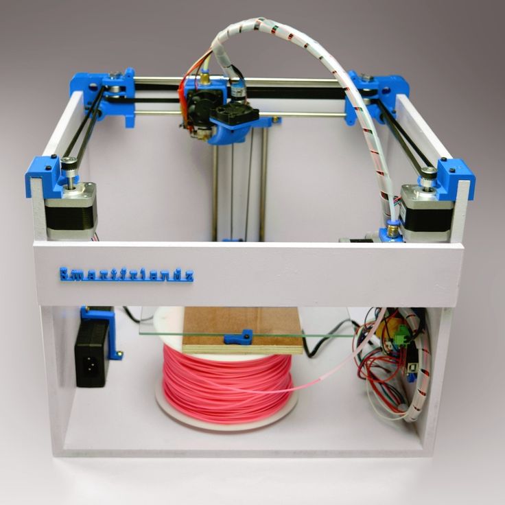 This can lead to deformation of the printed model, distortion of dimensions and proportions, clogging of the extruder (when the nozzle is close to the table and the plastic cannot come out).
This may be caused by a missing thread lock and poor quality platform leveling screws. Also, the error can be caused by the user's actions, for example, if he unevenly pasted adhesive tape on the printed table. nine0005
To avoid problems, the user should calibrate the platen regularly. In budget models, this work is done manually. To do this, the table is equipped with adjusting screws. However, there are models of 3D printers on the market with auto-calibration of the print bed, which greatly simplifies the operation of the printer.
The principle of auto-calibration of the 3D printer table
Source: all3dp.com
As follows from the definition, auto-calibration of the 3D printer table is a mechanism that allows you to automatically adjust the device.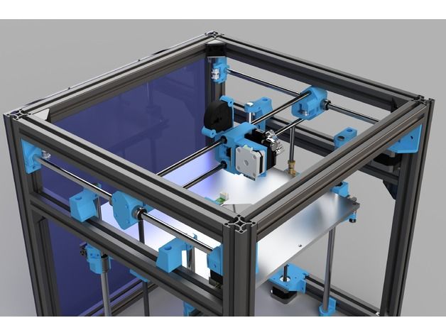 Before printing, the 3D printer determines the position of the print bed relative to the extruder and, if necessary, adjusts the position of the nozzle during printing. nine0005
Typically, an auto-leveling 3D printer has a proximity sensor or contact tip sensor at the level of the print head nozzle that "probes" certain points on the platform when the auto-calibration process is initiated. Sometimes, equipped with a feedback encoder, the extruder itself serves as such a sensor, and the nozzle is its probe.
One of the advantages of auto calibration is that it allows you to print a quality product, even if there are visually imperceptible irregularities on the table. Such a situation may occur during long-term operation of the device at high heating temperatures of the printing table. nine0005
Since the 3D printer automatically adjusts the position of the nozzle relative to the plane, the nozzle is always at the optimal distance from the printed model during the operation of the device.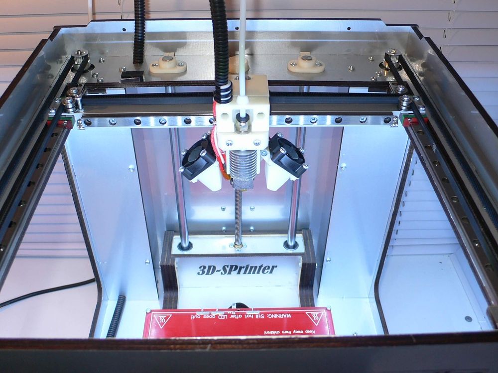 This, in particular, improves the adhesion of layers and print quality.
When using non-professional FDM 3D printers, especially from the DIY category (self-assembled, supplied as a kit), there are extensive upgrade options, including the ability to install the sensor required for auto-calibration. nine0005
Auto-calibration using the example of Simplify3D
Source: simplify3d.com
Consider setting up auto-calibration using one of the most popular professional 3D printing software, Simplify3D, as an example.
If the 3D printer has an automatic build plate alignment feature, then the Simplify3D profile for the machine must be set to auto-calibrate at the start of each print.
If you are using the printer for the first time, you can download the default Simplify3D profile for a specific device by selecting Help > Setup Assistant in the program.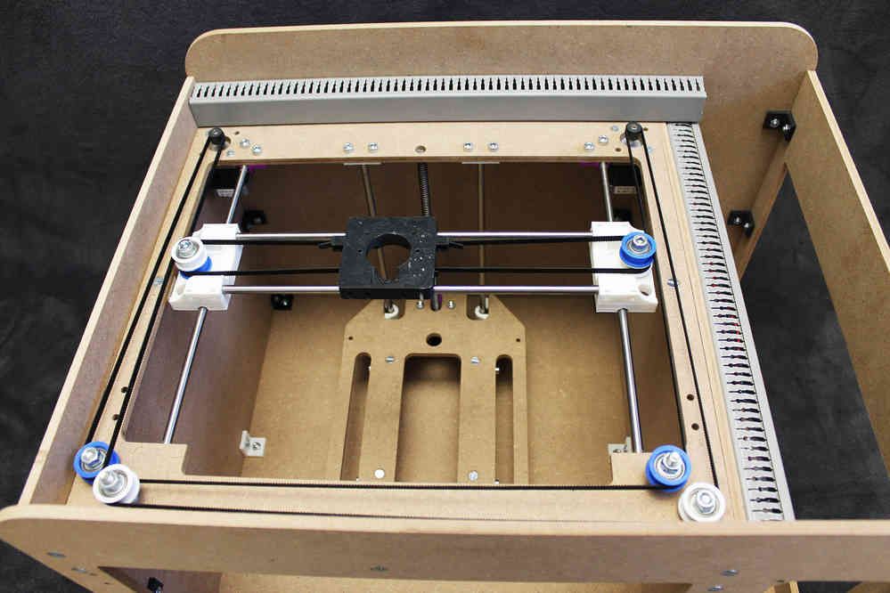 After loading the profile, click "Change process settings", go to the "Scripts" tab and select the startup script. This set of commands defines the actions that the 3D printer will perform at the start of each print. nine0005
Source: simplify3d.com
To auto-calibrate the 3D printer, edit the G-code of the script. To do this: at the beginning of the file, you need to add the G29 command, which tells the printer that you need to perform the table auto-calibration process. In this case, the 3D printer must perform a standard homing operation before it starts the alignment process, i.e. the G29 command must be placed after the G28 command (homing command) in the script. nine0005
Startup scenarios may vary depending on the model. There are several different types of G28 commands, such as the regular "G28" (all-axis coordinate origin), "G28 X0 Y0" (X and Y origin only), or "G28 Z0" (Z-axis origin only). For the script to work correctly, the G29 command must come after the most recent G28 command.
Source: simplify3d.com
After making these changes, you must save the new printer settings. To check if the changes were successful, it is enough to start a new print on the 3D printer and make sure that the table auto-calibration process is performed at the beginning of the print. nine0005
The auto-leveling process is mainly controlled by the firmware, so the exact locations where the sensor moves are already predefined on the machine. It remains for the user to add the command indicated above, and the printer will do the rest - it will set up the autolevel of the table.
Total
The auto-calibration process simplifies 3D printing by eliminating the need for time-consuming manual adjustments. A self-calibrating 3D printer guarantees a quality result every time you print.