3D printing stl binary or ascii
5 vital things to know about STL file format in 3D printing
When designing any 3D model, one will likely encounter a variety of file extension types to save drawings. There are many file formats that are used for 3D printing such as OBJ, VRML, PLY, etc. The most common file format for 3D printers is STL (.stl).
STL was first developed for stereolithography in the late 1980s. It was created to prepare CAD data for 3D printers. Since then, it was considered as the “standard” file format for 3D printing.
In order to understand this file type better, below are 5 vital things you need to know about STL file format.
1. What is STL file?STL format is the most commonly used format file for 3D printing. An STL (Standard Tessellation Language or STereoLithography) file is a format that describes surface geometry of a 3D object without any colour, texture or other attributes.
This format uses a series of linked triangles to recreate or reproduce surface geometry of the 3D model. The more triangles used, the higher resolution the 3D model will have.
STL file is widely used because it is simple, light and easy to be handled by 3D machines and software.
2. Limitations of STL filesAlthough STL is the most widely used file format for 3D printing, it also has its own limitations. STL only understands the external surface and shape of the 3D model.
The second biggest problem regarding STL files is the gaps and overlaps of joining surfaces in model that are not drawn correctly. These are known as non-manifold edges e.g. a door in a building has a air gap all around the door and is not connected solidly so cannot be 3D printed in the model.
Furthermore, information such as colour, internal structure, texture or attributes that a CAD file holds may not be included in an STL file.
3. Exporting STL files using different CAD softwareExporting an STL file is one of the steps in creating 3D printed models. Exporting STL files may differ in each CAD software. As a quick reference, here are some of the steps for exporting STL files.
- Tinkercad
Design > Download for 3D printing > .stl
- Autodesk Inventor
1. Select IPro > Print > 3D Print Preview
2. Select Options then choose desired resolution > Click Ok
3. In the preview window, Select Save Copy As or Send to 3D Print Service
4. Save As to STL file (*.stl)
- SketchUp
In SketchUp, creating STL files directly within the program may not be possible. An extension for .stl must be downloaded first in order to export STL files.
1. Download and install DXF or STL plugin
2. Select Tools > Export to DXF or STL > select the units (in millimetres) for the model
- Solidworks
1. File > Save As
2. Set Save As file type to STL
3. Options > Resolution > Fine or Custom > Ok
- Fusion 360
1. File > 3D Print
2. Under Refinement / Refinement options, select export settings.
3. Output > untick “Send to 3D Print Utility” > OK > Save
4. Important settings when exporting STL filesBelow are some of the most important settings when exporting STL files. These settings will result in good quality prints and file size.
- Angle control
To improve the print resolution, it is recommended to have gaps between triangles and change its angle deviation between adjacent triangles. In this way, it will be easier to adjust how close objects are layered or tiled together.
- Chordal deviation
Chord height is the maximum distance between the surface of the original design and STL mesh. Choosing the right tolerance will give you smoother and not pixelated 3D part.
The chord tolerance should be set between 0.01 to 0.001 millimetres. This setting usually results in good 3D prints.
- Binary or ASCII
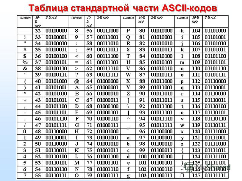
STL files can store information in two different ways. These are Binary encoding and ASCII encoding. Binary files are smaller and easier to share while ASCII files are visually easy to read and check.
Binary format is recommended to use for 3D printing. However, ASCII format is suggested for those who want to manually inspect STL file for debugging.
5. Special rules for STL filesThere are special rules for tessellation and storing information for STL files. Below are some of them.
- Vertex to vertex rule
In STL formatting, this rule states that each triangle must share 2 vertices with its neighbouring triangles. This means that a vertex of one triangle must not lie on the side of another triangle.
- Orientation rule
This rule states that the orientation of the facet must be defined clearly. This orientation is specified in two ways.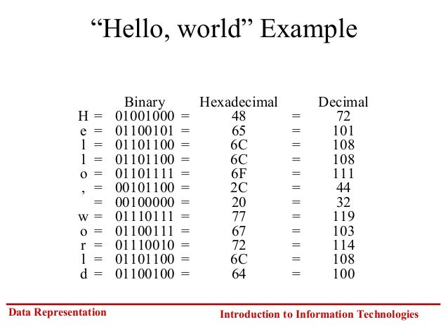 First, the direction of normal vector should point outwards. Moreover, the vertices should be listed in counter-clockwise order when looking at the object from the outside (or right-hand rule).
- All-positive Octant rule
This rule states that all the coordinates of the triangle vertices must be positive (nonnegative and nonzero).
If the 3D part is allowed to lie anywhere in the coordinate space, then negative coordinates may occur. The problem is, when storing negative coordinates, one must use “signed floating pointing numbers”. These numbers may require an additional bit to store a sign (+/-).
Hence, it is important to ensure that all coordinates are positive. When all the coordinates are positive, it also means that more space will be saved.
STL file is an important aspect in 3D printing since it serves as an interface between 3D model and 3D printer. Moreover, it is important to know about STL files especially if you are planning to DIY 3D printing.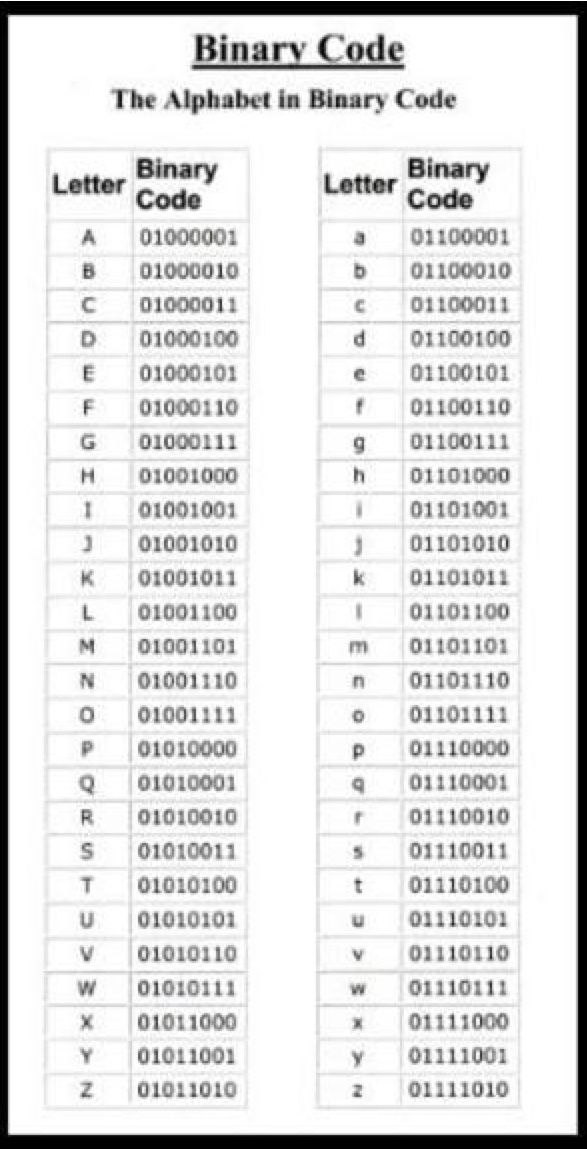 With this guide, you now have an in-depth understanding of how STL file format works.
If you are starting with 3D printing, you can ask a professional to design the 3D models for you. A reliable 3D printing service company can provide services such as 3D design and printing, custom 3D printing, industrial 3D printing, etc.
3d models - Export STL as ASCII or binary?
Asked
Modified 1 year, 10 months ago
Viewed 19k times
$\begingroup$
When go to export a model using Fusion 360 or Meshmixer, I see that there are two options. Could the final model be affected by the format chosen at the time of saving?
- 3d-models
- stl
$\endgroup$
$\begingroup$
The two formats contain the same information about the model, but the binary format is much more compact, so it will produce smaller files from the same part but they should work the same. That's to say, if you take the exact same model, save it as a binary STL and as an ASCII STL, the binary STL file will take up fewer bytes on disk. The number of triangles and the dimensions of the printed model will stay the same.
There are a couple of important exceptions here:
I don't know about Meshmixer specifically, but some tools will have completely different code paths for exporting the two formats. One exporter may have a bug that the other exporter doesn't. The same is true of the slicer, which may have a bug reading one of the two kinds of STL but not the other. In this case, it'll make a huge difference which one you use, but you'll only find out when one goes wrong. This is what fred_dot_u experienced in his answer.
Some tools have a way of putting colour information into the binary STL format, which isn't possible with the ASCII format. If your model has coloured triangles, you might find that the binary STL preserves the colours, while the ASCII STL loses the colours.
 Whether this matters to you depends on what printing technology you'll be using. Most slicers can't use these colours anyway - and subsequently, ignore color information on import.
The ASCII STL format is older than the binary format, so you may find some very old software can only understand the ASCII STL files, but unless you're working with such old software, it's usually better to use the binary format. Smaller files don't just save disk space: they're also faster to process and transfer via e-mail or on servers.
$\endgroup$
3
$\begingroup$
You should always pick the binary option. ASCII files are larger and slower to save and load. There's no reason to ever use ASCII unless you are using software that is incompatible with binary files.
Could the final model be affected by the format chosen at the time of saving?
In practice, the model will not be affected by either choice. There are some subtle differences between the two formats, such as binary being able to store an attribute per triangle (which is sometimes used to represent colour), ASCII being able to store a "name" for the solid in a file while binary can store an 80-byte header containing metadata, binary being limited to 32 bits of precision while ASCII theoretically has the option to use arbitrary precision. However, for 99.9% of all use cases there is no difference, so it is preferable to use binary for its smaller file size.
$\endgroup$
1
$\begingroup$
I have experienced problems on occasion when using a binary exported Meshmixer model. The slicers used have been Simplify3D and Prusa Slicer 2.0 and possibly an earlier version. I've not attempted to resolve the problem other than to change that specific model to export to ASCII which then solves the problem. ASCII files will be larger but that's not a significant factor, in my opinion.
If you are using a program which fails to properly process a binary export, it's simple enough to overwrite the model in ASCII form.
$\endgroup$
3
$\begingroup$
The other answers on this thread seem kind of hand-wavy, so I'll give my input.
At its simplest, all we're dealing with here is two different formats of encoding the same data. The 3D file is identical, just described by the file data in different terms.
That being said, there is a multitude of different reasons that 3D prints can fail. Fusion 360 is notorious for having issues with slicers because of fillets, lofts, smooth-curvy type patterns, or intersecting planes.
Binary is a smaller encoding. It almost always works for me. ASCII has never failed me as a backup when binary did.
$\endgroup$
1
(Solution available) Export STL as ASCII or binary?
3d models stl
When I go to export the model with Fusion 360 or Meshmixer I see that there are two options. Can the final model be affected by the format chosen at save time?
@Pedro Miguel Pimienta Morales, 👍8
4 answers0019 is much more compact than
, so it will produce smaller files from the same part, but they should work the same way. This means that if you take exactly the same model, save it as a binary STL and as an ASCII STL, the binary STL file will take up fewer bytes than on disk. The number of triangles and dimensions of the printed model will remain the same as .There are a few important exceptions here:
-
I don't know about Meshmixer specifically, but some tools will have completely different code paths for exporting the two formats.
 One exporter may have a bug that another exporter does not. The same applies to a slicer, which may have an error reading one of the two kinds of STL, but not the other. In this case, it will make a huge difference which one you use, but you'll only know when something goes wrong. This is what fred_dot_u experienced in his answer. nine0003
 -
Some tools may put the color information in binary STL format, which is not possible in ASCII format. If your model has colored triangles, you may find that the binary STL retains the colors while the ASCII STL loses the colors. Whether or not this matters to you depends on what printing technology you will be using. Most slicers can't use these colors anyway - and subsequently ignore the color information on import.
The ASCII STL format is older than the binary format, so you may find that some very old programs can only understand ASCII STL files, but unless you are working with such old software it is usually better to use the binary format. Smaller files don't just save disk space, they're also faster to process and share via email or servers.
, @ Dan Hulme
▲ 2
I have occasionally experienced problems using the binary exported meshmixer model. Slicing was used in Simplify3D and Prusa Slicer 2.0 and possibly earlier. I didn't try to solve this problem other than to change that particular model to export to ASCII which then solves the problem. ASCII files will be larger, but this is not a significant factor in my opinion.
If you are using a program that cannot properly handle binary exports, simply overwrite the model as ASCII. nine0003
, @ fred_dot_u
▲ 4
You should always choose the binary option. ASCII files are larger and slower to save and load. There is no reason to ever use ASCII unless you are using software that is not binary compatible.
Can the final model be affected by the format selected at the time of saving?
In practice, the model will not be affected by any of the options. There are some subtle differences between the two formats, such as binary being able to store an attribute per triangle (which is sometimes used to represent color), ASCII being able to store the "name" of a solid in the file, while binary being able to store an 80-byte header containing metadata, binary is limited to 32 bits of precision, while ASCII can theoretically use arbitrary precision. However, at 9In 9.9% of all use cases there is no difference, so binary is preferred for its smaller file size.
, @ Tom van der Zanden
▲ 1
The other answers in this thread seem a bit squiggly by hand, so I'll contribute.
Simply put, all we're dealing with here are two different encoding formats for the same data. The 3D file is identical, just described by the file data in different terms. nine0003
However, there are many different reasons why 3D printing can fail. Fusion 360 is infamous for its slicer issues due to fillets, lofts, smooth serpentine type patterns, or intersecting planes.
Binary is a smaller encoding. I almost always get it. ASCII never failed me as a fallback when binary did.
, @ Christopher Larson
STL file format for 3D printing - Knowledge
What is this STL file? What is this for? How it works? We just explain the 3D printing STL file format in detail.
Here's a brief description of what they are and how they work, the advantages and disadvantages of using them, and alternative file formats to consider. In this article, we are talking about the 3D printing file format, not the standard C++ template library.
1. What is an STL file? nine0102
In short, an STL file stores information about 3D models. This format only describes the surface geometry of a 3D object without any representation of color, texture, or other general model attributes.
These files are typically created by computer-aided design (CAD) software as the end product of the 3D modeling process. ".STL" is the file extension of the STL format.
The STL file format is the most commonly used file format for 3D printing. When used in conjunction with a 3D slicer, it allows the computer to communicate with the 3D printer hardware. nine0003
Since the beginning, the STL file format has been adopted and supported by many other CAD software packages, and is now widely used for rapid prototyping, 3D printing, and computer-aided manufacturing. It is used by both amateurs and professionals.
2. What does the .STL file extension mean?
The true meaning of the .STL file extension has been lost to the mists of time.
It is widely believed to be short for STereoLithography, although it is sometimes also referred to as "Standard Triangle Language" or "Standard Tessellation Language". nine0003
3. How is the 3D model stored in the STL file format?
The main purpose of the STL file format is to encode the surface geometry of a 3D object. It encodes this information using a simple concept called "tessellation".
3.1 Tessellation
Tiled walls and floors are simple examples of real life mosaics.
Tessellation is the process of tiling a surface with one or more geometric shapes so that there are no overlaps or gaps. If you've ever seen a tiled floor or wall, this is a good real life example of tessellation. nine0003
Tessellation can include simple geometric shapes or very complex (and creative) shapes. Here are some examples of artistic mosaics created by renowned artist M.K. Escher. In fact, if you want to see more examples of stunning mosaics, we encourage you to check out his paintings.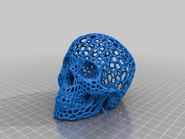
Two mosaic paintings by M.S. Escher
3.2 Invention of the STL File Format: Using Tessellation to Encode Surface Geometry
Back in 1987, Chuck Hull had just invented the first stereolithographic 3D printer, and the Albert Consulting Group for 3D Systems was trying to find a way to communicate information about 3D CAD models to a 3D printer. They realized that they could use the surface tessellation of a 3D model to encode this information! nine0003
The basic idea was to tessellate the 2D outer surface of 3D models using tiny triangles (also called "facets") and store the facet information in a file.
Let's look at some examples to understand how this works. For example, if you have a simple 3D cube, you can cover it with 12 triangles, as shown in the image below. As you can see, there are two triangles on each face. Since the cube has six sides, there are 12 triangles. nine0003
If you have a 3D model of a sphere, it may be covered with many small triangles, which are also shown in the same image.
Cube and Sphere Tessellations
Here is another example of a very complex 3D shape that has been tiled with triangles.
Mosaic of a 3D pig (source: i.materialize)
The Albert Consulting Group for 3D systems realized that if they could store information about these tiny triangles in a file, that file could completely describe the surface of an arbitrary 3D model . This formed the basic idea of the STL file format! nine0003
4. How does an STL file store facet information?
The STL file format provides two different ways to store information about triangular faces that are tiled on the surface of an object. This is called ASCII encoding and binary encoding. Both formats store the following information about each triangle:
-
Vertex coordinates.
-
Triangle unit normal vector components. The normal vector must point outward in relation to the 3D model. nine0003
The STL file stores the coordinates of the vertices and the components of the unit normal vector to the facets.
4.1 ASCII STL file format
The ASCII STL file starts with a mandatory string:
solid
where is the name of the 3D model. The name can be left empty, but in this case there must be a space after the word.
The file continues with covering triangle information. The vertex and normal vector information is presented as follows:
 normal face
 outer loop
 vertexv1xv1yv1z
 vertexv2xv2yv2z
 vertexv3xv3yv3z
 loop end
 end
Coordinate values are represented as a floating-point number in the format sign-mantissa-e-sign-exponent, such as "3.245000e-002".
The file ends with the mandatory string:
endolid
4.2 STL 9 binary file format0015
If the tessellation includes many small triangles, the ASCII STL file can become huge. That's why there is a more compact binary version.
An STL binary file starts with an 80-character header. This is generally ignored by most readers of STL files, with a few notable exceptions that we'll talk about later. The header is followed by the total number of triangles using a 4-byte unsigned integer.
 UINT8 [80] - header
 UINT32 - Number of triangles
Information about triangles will follow. The file just ends after the last triangle.
Each triangle is represented by twelve 32-bit floating point numbers. As in the ASCII STL file, the 3 numbers are the Cartesian 3D coordinates of the normal to the triangle. The remaining 9 numbers are the coordinates of the vertices (three each). Here's what it looks like:
 front triangle
 REAL32 [3] -normal vector
 REAL32 [3] -Vertex1
 REAL32 [3] -Vertex2
 REAL32[3] -Vertex3
 UINT16 - Attributebytecount
 end
Note that after each triangle there is a 2-byte sequence called "attribute byte count". In most cases it is set to zero and acts as a delimiter between two triangles. But some programs also use these 2 bytes to encode additional information about the triangle. Later we will see an example where these bytes will be used to store color information. nine0003
5. Special rules for STL format.
The STL specification has some special rules for tessellation and information storage.
5.1 Vertex rule
The supernatural largest triangle must separate two vertices by neighboring triangles.
This rule must be observed when tessellation of the surface of a 3D object.
Here is an example of valid and invalid tessellation according to this rule. The figure on the left violates this rule and is an invalid tessellation, while the figure on the right complies and is a valid tessellation. nine0003
Vertex rule for STL files: the picture on the left is an invalid tessellation and the picture on the right is valid.
5.2 Orientation rule
The orientation rule states that the orientation of a facet (that is, which path is "inside" the 3D object and which path is "outside") must be specified in two ways.
First, the direction of the normal must point outward. Second, the vertices are listed in counter-clockwise order when viewed from the outside (the right-hand rule). nine0003
The orientation of each face is specified in two ways: by the direction of the normal vector and by the order of the vertices.
This redundancy exists for a reason. This helps ensure data consistency and detects corrupted data. The software can, for example, calculate the orientation from the normal and then from the vertices and check if they match. If it doesn't, it may declare the STL file to be corrupt!
5.3 Positive octant rule
The positive octant rule states that all triangle vertex coordinates must be positive.
This means that the 3D object lives in the positive octant of the 3D Cartesian coordinate system (hence the name).
The purpose of this rule is to save space. If a 3D object were allowed to live anywhere in coordinate space, we would have to deal with negative coordinates. To store negative coordinates, you must use signed floating point numbers. Signed floating point numbers require one extra bit to store the sign (+/-). By ensuring that all coordinates are positive, this rule ensures that we can use unsigned numbers for coordinates and save a little for each coordinate value we store. nine0003
Octant I (red) is a fully positive octant
5.4 Triangle Sorting Rule
This helps slicers cut 3D models faster. However, this rule is not strictly enforced.
How is an STL file printed in 3D?
For 3D printing, the STL file must be opened in a special slicer. What is a slicer? This is a piece of 3D printing software that converts digital 3D models into instructions for your 3D printer to create an object. nine0003
Slicer slices your STL file into hundreds (sometimes thousands) of flat horizontal layers depending on the settings you choose and calculates how much material your printer will need to extrude and how long it will take.
All of this information is then combined into a GCode file, your 3D printer's native language. Slicer settings do affect the quality of your print, so it's important to have the right software and settings to get the best print quality possible. nine0003
Once the GCode has been downloaded to your 3D printer, the next step is to reassemble these individual 2D layers as a 3D object on your build bed. This is done by applying a succession of thin layers of plastic, metals, or composite materials and building the model one layer at a time.
More info: 3D Slicer Settings for Beginners - 8 Things You Need to Know
Can every STL file be printed in 3D? nine0102
Unfortunately not. Only 3D designs specifically created for 3D printing are 3D printable. An STL file is just a container for data, not a guarantee that something can be printed.
3D models suitable for 3D printing must have a minimum wall thickness and "watertight" surface geometry in order to be 3D printed. Even if it's visible on a computer screen, it's impossible to print anything with zero wall thickness.
Protruding elements of the model are also taken into account. Look at the ALL3DP logo in the picture above; if the model is printed in a vertical position, then supports (shown in green) will be required for protruding elements with an angle of more than 45 degrees. nine0003
When uploading an STL file that you didn't create yourself, it's worth taking the time to make sure it's actually 3D printable. This will save you a lot of time and nerves (and wasted thread).
Further Reading: MeshMixer Tutorial for 3D Printing Beginners 9 Important 3D Printing Concepts Everyone Should Know
8. Optimizing the STL file for better 3D printing performance.
The STL file format approximates the surface of a CAD model with triangles. The approximation is never perfect, and the edges make the model rough. nine0003
The ideal spherical surface on the left is approximated by a mosaic. The figure on the right uses large triangles to give a rough model. The shape in the center is made up of smaller triangles and provides a smoother zoom (source: i.materialize).
The 3D printer will print the object with the same degree of roughness as specified in the STL file. Of course, by making the triangles smaller and smaller, you can get better and better approximations, resulting in good quality prints. However, as the size of the triangle decreases, the number of triangles required to cover the surface also increases. This results in a giant STL file that 3D printers can't handle. It is also difficult to share or upload such huge files. nine0003
Finding the right balance between file size and print quality is therefore very important. It makes no sense to reduce the size of the triangles to infinity, because at some point your eye will not be able to distinguish the print quality.
Most CAD programs offer several options when exporting STL files. These settings control the size of the facets and hence the print quality and file size. Let's dive into the most important settings and find out their optimal values.
8.1 Chord height or tolerance
Most CAD programs allow you to select a parameter called chord height or tolerance. The height of the belt is the maximum distance from the surface of the original design and the STL mesh. If you choose the right tolerance, your prints will look smooth, not pixelated. It is quite obvious that the smaller the height of the chord, the more accurately the faces represent the real surface of the model.
Chord height is the height between the STL mesh and the real surface (source: www.3dhubs.com) [/ caption]
A tolerance of 0.01 to 0.001 mm is recommended. This usually results in good quality prints. There is no point in reducing this further since 3D printers cannot print at this level of detail.
8.2 Angular deviation or angular tolerance
Angular tolerance limits the angle between the normals of neighboring triangles. The default angle is usually 15 degrees. Decreasing the tolerance (from 0 to 1) improves print resolution.
Angular tolerance is the angle between the normals of neighboring triangles (source: www.3dhubs.com)
The recommended value for this parameter is 0.
8.3 Binary or ASCII?
Finally, you have the choice of exporting the STL file to binary or ASCII format. For 3D printing, it is always recommended to use the binary format as it results in smaller file sizes. However, if you want to manually check the STL file for debugging, ASCII is preferred because it's easier to read.
9. Are there alternatives to the STL file format?
The STL file format is not the only format used in 3D printing. There are over 30 file formats for 3D printing. The most important is the OBJ file format, which can store color and texture profiles. Another option is the Polygon (PLY) file format, which was originally used to store 3D scanned objects.
More recently, attempts have been made to launch a new file type with the 3MF Consortium, which proposes a new file format for 3D printing called 3MF. They claim that this will streamline and improve the 3D printing process. nine0003
To make it happen, Microsoft is partnering with companies like Autodesk, HP, and Shapeways to make their dream come true. You can read more about the 3MF Consortium on their website, along with preliminary documentation on the 3MF file type, on their GitHub page. However, it is still too early to tell if this will become widespread.
10. Advantages and disadvantages of using the STL file format over other file formats.
Since there are many file formats for 3D printing, the obvious question is which one should be used for printing? The answer, as it turns out, depends a lot on your use case. nine0003
10.1 When not to use an STL file
As we saw earlier, the STL file format cannot store additional information such as color, material, etc. edges or triangles. It only stores information about the vertices and the normal vector. This means that if you want to use multiple colors or multiple materials for your prints, then the STL file format is not the right choice. The OBJ format is a well-supported popular format that has the ability to specify color, material, etc. Hence, it is the right choice for this task. nine0003
10.2 When to use an STL file
On the other hand, if you want to print using a single color or material, which is most often the case, then STL is better than OBJ because it is simpler, resulting in smaller file sizes and faster processing.
10.3 Other advantages of the STL file format
Versatility: Another great advantage of the STL file format is that it is universal and is supported by almost all 3D printers. The same cannot be said for the OBJ format, although it also enjoys reasonable support and acceptance. The VRML, AMF, and 3MF formats are not currently widely supported. nine0003
Mature ecosystem: Most of the 3D printable models you can find on the Internet are in the STL file format. The existence of this ecosystem, coupled with the investment in STL-based software made by 3D printer manufacturers, has resulted in a large user base that is heavily investing in the format. This means that a lot of third-party software works with STL files, which is not the case with other file formats.
10.4 Some disadvantages of the STL 9 file format0015
There are obvious disadvantages to using the STL. Because the precision of printing processes includes micron-scale resolution, the number of triangles required to describe smooth, curved surfaces can result in huge file sizes. It is also not possible to include metadata (such as attribution and copyright information) in an STL file.
10.5 Verdict
If your 3D printing needs are simple, there may be no reason to move away from the STL file format. However, for more complex prints using multiple materials and colors, it may be a good idea to try OBJ or other available formats. nine0003
11. Color in STL file format
In the last section, we said that the STL file format cannot handle multi-color models. The reason why there is no color information in the STL file format is simple. When rapid prototyping came along in the 1980s, no one thought about color printing. Currently, materials and processes for 3D printing are developing rapidly. Some allow you to print in full color - just imagine a 3D sandstone selfie as shown above. nine0003
However, it wouldn't be entirely fair to say that STL can't handle colors. It turns out that there are non-standard versions of the STL format that are actually capable of carrying color information.
For example, the VisCAM and Solidview software packages use an "attribute byte count" at the end of each triangle to store a 15-bit RGB color using the following system:
-
bits 0 to 4 for blue (0 to 31),
-
bits 5 to 9 for green (0 to 31),
-
bits 10 to 14 for red (0 to 31),
-
bit 15 is 1 if the color is valid, or 0 if the color is valid if the color is invalid (as with normal STL files).
The Materialize Magics software, on the other hand, uses an 80-byte binary header to represent the overall color of a 3D object. A color is defined by including the ASCII string "COLOR=" followed by four bytes representing red, green, blue, and alpha channel (transparency) in the range 0-255. This base color can also be overridden on a per-aspect basis using the "attribute byte count" bytes. nine0003
12. STL File Resources
If you've read this far, congratulations! Now that you know a little about STL, you can no doubt call yourself an expert on STL file formats.
In this last section, we will share some amazing software and resources that you can use to download, view, edit, and restore STL files.
12.1 Downloading STL Files
There are many repositories, marketplaces, and search engines on the web containing literally millions of free STL files. You can refer to our regularly updated list - Best Sites 2020 for Free STL Files & 3D Printer Models - or you can choose one of these models to get started: 50 Cool Things to 3D Print in November 2020
12.2 Opening and viewing an STL file
Fortunately, opening an STL file is not that difficult. There are several free STL file viewers for this purpose that can be used online or as a desktop application. Refer to our dedicated guide here: 2020 Best Free STL File Viewer
12.3 Editing and Converting STL File
Yes, you can edit STL file and convert STL file to other file format. Since the format is open, there is nothing to prevent you from changing the contents of the file. In fact, the editing process is quite simple. We have a dedicated article on this topic: 7 Free STL Editors: How to Edit & Restore STL 9 Files0003
12.4 Recovering an STL file
Remember the section in which we discussed the rules that STL files must satisfy? For example, adjacent triangles must share two vertices, and the right-hand rule applied to the vertices must result in the same orientation as the normal vector. If these conditions are violated in an STL file, then it is damaged or damaged.
There are several programs that can help repair a damaged STL file. For example, Netfabb Basic is a great tool for fixing the most common problems with STL files. For more information on these programs, please see our article: Best Free 3D Printing Software 2020 (Fall Update)
13. Conclusion
In conclusion, we learned how the STL file format encodes the layout of 3D models. We have discussed how to optimize STL files for the best 3D printing quality.


